1
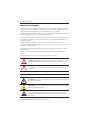
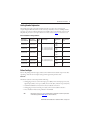
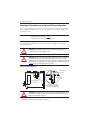
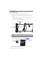
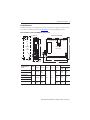
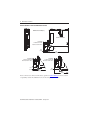
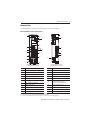
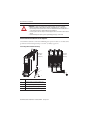
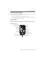
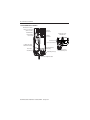
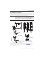
Installation Instructions
Kinetix 5500 Servo Drives
Catalog Numbers 2198-H003-ERS, 2198-H008-ERS, 2198-H015-ERS, 2198-H025-ERS,
2198-H040-ERS, 2198-H070-ERS, 2198-H003-ERS2, 2198-H008-ERS2, 2198-H015-ERS2,
2198-H025-ERS2, 2198-H040-ERS2, 2198-H070-ERS2
Topic
Page
About the Kinetix 5500 Drives
1
Important User Information
2
Catalog Number Explanation
3
Before You Begin
3
Removing the Grounding Screws in Ungrounded Power Configurations
4
Install the Kinetix 5500 Servo Drive
5
Connector Data
9
Wiring Requirements
12
Attach the Motor Cable Shield Clamp
15
Motor Overload Protection
18
Additional Resources
19
About the Kinetix 5500 Drives
Kinetix® 5500 servo drives provide an Integrated Motion over the EtherNet/IP network solution
for applications with output power and current requirements in the range of 0.2…14.6 kW and
1.4…32.5 A 0-pk, respectively.
Refer to the Kinetix 5500 Servo Drives User Manual, publication 2198-UM001, for detailed
information on wiring, applying power, troubleshooting, and integration with ControlLogix®
EtherNet/IP network modules or CompactLogix™ 5370 controllers.
2 Kinetix 5500 Servo Drives
Important User Information
Read this document and the documents listed in the additional resources section about installation, configuration, and operation of
this equipment before you install, configure, operate, or maintain this product. Users are required to familiarize themselves with
installation and wiring instructions in addition to requirements of all applicable codes, laws, and standards.
Activities including installation, adjustments, putting into service, use, assembly, disassembly, and maintenance are required to be
carried out by suitably trained personnel in accordance with applicable code of practice.
If this equipment is used in a manner not specified by the manufacturer, the protection provided by the equipment may be impaired.
In no event will Rockwell Automation, Inc. be responsible or liable for indirect or consequential damages resulting from the use or
application of this equipment.
The examples and diagrams in this manual are included solely for illustrative purposes. Because of the many variables and
requirements associated with any particular installation, Rockwell Automation, Inc. cannot assume responsibility or liability for actual
use based on the examples and diagrams.
No patent liability is assumed by Rockwell Automation, Inc. with respect to use of information, circuits, equipment, or software
described in this manual.
Reproduction of the contents of this manual, in whole or in part, without written permission of Rockwell Automation, Inc., is
prohibited.
Throughout this manual, when necessary, we use notes to make you aware of safety considerations.
WARNING: Identifies information about practices or circumstances that can cause an explosion in a hazardous
environment, which may lead to personal injury or death, property damage, or economic loss.
ATTENTION: Identifies information about practices or circumstances that can lead to personal injury or death,
property damage, or economic loss. Attentions help you identify a hazard, avoid a hazard, and recognize the
consequence.
IMPORTANT Identifies information that is critical for successful application and understanding of the product.
Labels may also be on or inside the equipment to provide specific precautions.
SHOCK HAZARD: Labels may be on or inside the equipment, for example, a drive or motor, to alert people that
dangerous voltage may be present.
BURN HAZARD: Labels may be on or inside the equipment, for example, a drive or motor, to alert people that
surfaces may reach dangerous temperatures.
ARC FLASH HAZARD: Labels may be on or inside the equipment, for example, a motor control center, to alert
people to potential Arc Flash. Arc Flash will cause severe injury or death. Wear proper Personal Protective
Equipment (PPE). Follow ALL Regulatory requirements for safe work practices and for Personal Protective
Equipment (PPE).
Rockwell Automation Publication 2198-IN001C-EN-P - January 2014
Kinetix 5500 Servo Drives 3
Catalog Number Explanation
This publication applies to the following Kinetix 5500 servo drives. For connecting safe
torque-off signals, hard-wired drives use the safe torque-off (STO) connector and ship with the
protective cover removed. Networked safe torque-off drives do not use the STO connector and
ship with the protective cover in place. Refer to Connector Data on page 9 to locate the cover.
Kinetix 5500 Drive Catalog Numbers
Drive Cat. No.
(hard-wired STO)
Drive Cat. No.
(networked STO)
2198-H003-ERS
2198-H003-ERS2
2198-H008-ERS
2198-H008-ERS2
2198-H015-ERS
2198-H015-ERS2
2198-H025-ERS
2198-H025-ERS2
2198-H040-ERS
2198-H040-ERS2
2198-H070-ERS
2198-H070-ERS2
Frame
Size
Input Voltage
Continuous
Output Power
kW
Continuous
Output Current
A 0-pk
0.2 kW
0.3 kW
0.6 kW
1.4
0.5 kW
0.8 kW
1.6 kW
3.5
1.0 kW
1.5 KW
3.2 kW
7.1
2.4 kW
5.1 kW
11.3
4.0 kW
8.3 kW
18.4
7.0 kW
14.6 kW
32.5
1
195…264V rms, single-phase
195…264V rms, three-phase
324…528V rms, three-phase
2
195…264V rms, three-phase
324…528V rms, three-phase
3
Before You Begin
Remove all packing material, wedges, and braces from within and around the components. After
unpacking, check the item nameplate catalog number against the purchase order.
Parts List
The Kinetix 5500 servo drives ship with the following:
• Wiring plug connector set for mains input power (IPD), 24V control input power (CP),
digital inputs (IOD), motor power (MP), motor brake (BC), and safe torque-off (STO)
• 2198-KITCON-DSL connector kit for motor feedback connections
• Wiring plug connector for shunt power (RC) connections installed on the drive
• These installation instructions, publication 2198-IN001
TIP
Replacement connector sets are also available. Refer to the Kinetix Servo Drives Specifications
Technical Data, publication GMC-TD003, for more information.
Rockwell Automation Publication 2198-IN001C-EN-P - January 2014
4 Kinetix 5500 Servo Drives
Removing the Grounding Screws in Ungrounded Power Configurations
Removing the grounding screw is necessary only when using ungrounded or corner-grounded
power configurations. Removing the screws involves gaining access, opening the side door, and
removing the screws.
IMPORTANT
If you have grounded wye power distribution, you do not need to remove the screws. Go to
Install the Kinetix 5500 Servo Drive on page 5.
Removing the ground screws can affect EMC performance.
Removing the grounding screws in multi-axis configurations is best done when the drive is
removed from the panel and placed on its side on a solid surface equipped as a grounded
static-safe workstation.
ATTENTION: By removing the grounding screw for ungrounded power configurations, you no
longer maintain line-to-neutral voltage protection.
ATTENTION: This drive contains electrostatic discharge (ESD) sensitive parts and assemblies. You
are required to follow static-control precautions when you install, test, service, or repair this
assembly. If you do not follow ESD control procedures, components can be damaged. If you are not
familiar with static control procedures, refer to Guarding Against Electrostatic Damage, publication
8000-4.5.2, or any other applicable ESD awareness handbook.
Remove the Grounding Screws
Grounding Screw
Access Door
Lift door to meet
arrow at left.
Kinetix 5500 Drive
(side view)
Grounding screws installed
for grounded power configuration
(screws installed is default setting).
ATTENTION: Risk of equipment damage exists. The drive ground configuration must be accurately
determined. Leave the grounding screws installed for grounded power configurations (default).
Remove the screws for ungrounded power.
Rockwell Automation Publication 2198-IN001C-EN-P - January 2014
Kinetix 5500 Servo Drives 5
Grounding Screw Configurations
Ground Configuration (1)
Grounding Screw Configuration
Benefits of Configuration
Grounded (wye)
Both screws installed
(default setting)
•
•
•
•
• B-phase corner ground
• AC fed ungrounded
Both screws removed
• Helps avoid severe equipment damage when
ground fault occurs
• Reduced leakage current
(1)
UL and EMC compliance
Reduced electrical noise
Most stable operation
Reduced voltage stress on components and
motor bearings
Refer to the Kinetix 5500 Servo Drives User Manual, publication 2198-UM001, for example configurations.
Install the Kinetix 5500 Servo Drive
These procedures assume you have prepared your panel and understand how to bond your
system. For installation instructions regarding equipment and accessories not included here, refer
to the instructions that came with those products.
SHOCK HAZARD: To avoid hazard of electrical shock, perform all mounting and wiring of the
Kinetix 5500 drive prior to applying power. Once power is applied, connector terminals can have
voltage present even when not in use.
ATTENTION: Plan the installation of your system so that you can perform all cutting, drilling,
tapping, and welding with the system removed from the enclosure. Because the system is of the
open type construction, be careful to keep any metal debris from falling into it. Metal debris or
other foreign matter can become lodged in the circuitry and result in damage to components.
Rockwell Automation Publication 2198-IN001C-EN-P - January 2014
6 Kinetix 5500 Servo Drives
Mount the Kinetix 5500 Drive
Follow these steps to mount the drive in single-axis configurations.
1. Observe these clearance requirements when mounting a single drive to the panel:
• Additional clearance is required for cables and wires connected to the top of the
drive.
• Additional clearance left and right of the drive is required when mounted adjacent to
noise sensitive equipment or clean wire ways.
• The recommended minimum cabinet depth is 300 mm (11.81 in.).
40 mm (1.57 in.) clearance above
drive for airflow and installation.
Kinetix 5500
Servo Drive
Clearance left of the
drive is not required.
Clearance right of the
drive is not required.
40 mm (1.57 in.) clearance below
drive for airflow and installation.
IMPORTANT
Mount the drive in an upright position as shown. Do not mount the drive on its side.
In multi-axis shared-bus configurations, drives must be spaced by aligning the zero-stack
tab and cutout. For mounting, sizing, and configuring shared-bus configurations, refer to
the Kinetix 5500 Servo Drives User Manual, publication 2198-UM001.
Zero-stack Tab and
Cutout Aligned
Bus-bar system used in bus-sharing
configurations is not shown for clarity.
2. Mount the Kinetix 5500 drive to the cabinet subpanel with M4 (#8-32) steel machine
screws torqued to 2.0 N•m (17.7 lb•in), max.
Rockwell Automation Publication 2198-IN001C-EN-P - January 2014
Kinetix 5500 Servo Drives 7
Product Dimensions
Included in this figure are the drill hole patterns for standalone drives. Refer to the Kinetix 5500
Servo Drives User Manual, publication 2198-UM001, for multi-axis drill-hole patterns.
Kinetix 5500 Drives with 2198-KITCON-DSL Connector Kit
Dimensions are in mm (in.)
Ø M4 (#8-32)
F
G
34.00
(1.34)
E
B
2198-H003-ERS
Drive is Shown
Applies to
Only
Frame 3
0.0
0.0
52.50
(2.07)
C
3.0
(0.12)
A
D
Drill Hole Patterns
Kinetix 5500 Drive
Cat. No.
Frame
A
mm (in.)
B
mm (in.)
1
50 (1.97)
170
(6.69)
2
55 (2.16)
225
(8.86)
3
85.2
(3.35)
250
(9.84)
2198-H003-ERSx
2198-H008-ERSx
C
mm (in.)
D
mm (in.)
E
mm (in.)
F
mm (in.)
G
mm (in.)
215
(8.46)
193.68
(7.62)
4.51
(0.18)
265
(10.43)
243.84
(9.60)
5.00
(0.20)
294
(11.57)
273.70
(10.78)
0.0
2198-H015-ERSx
2198-H025-ERSx
200
(7.87)
226
(8.90)
2198-H040-ERSx
2198-H070-ERSx
Rockwell Automation Publication 2198-IN001C-EN-P - January 2014
8 Kinetix 5500 Servo Drives
Kinetix 5500 Drives with 2198-H2DCK Converter Kit
Dimensions are in mm (in.)
Frame 1 Servo Drive
2198-H2DCK
Feedback Converter Kit
Mounted on Frame 1 Drive
45.0
(1.77)
56.0
(2.20)
2198-H2DCK
Feedback Converter Kit
Mounted on Frame 3 Drive
2198-H2DCK
Feedback Converter Kit
Mounted on Frame 2 Drive
56.0
(2.20)
256
(10.08)
256
(10.08)
56.0
(2.20)
256
(10.08)
Refer to Kinetix Servo Drives Technical Data, publication GMC-RM003, for motor/actuator
compatibility with the 2198-H2DCK converter kit and product dimensions.
Rockwell Automation Publication 2198-IN001C-EN-P - January 2014
Kinetix 5500 Servo Drives 9
Connector Data
Use this illustration to identify the Kinetix 5500 drive features and indicators.
Kinetix 5500 Drive Features and Indicators
7
7
2
8
9
18
1
10
11
6
L3
5
19
L2
12
L1
13
U
4
+
V
14
W
–
1
2
3
2
1
20
21
15
17
2
1
16
Kinetix 5500 Drive, Top View
(2198-H003-ERS2 drive is shown)
Kinetix 5500 Drive, Front View
(2198-H003-ERSx drive is shown)
Item
Description
1
Motor cable shield clamp
2
Converter kit mounting hole (under cover)
3
Motor feedback (MF) connector
(1)
Item
Description
12
Link speed status indicators
13
Link/Activity status indicators
14
Motor power (MP) connector
4
Digital inputs (IOD) connector
15
Motor brake (BC) connector
5
Ethernet (PORT1) RJ45 connector
16
Ground terminal
6
Ethernet (PORT2) RJ45 connector
17
Safe torque-off (STO) connector (2)
(applies to only 2198-Hxxx-ERS drives)
7
Zero-stack mounting tab/cutout
8
Module status indicator
18
Shunt resistor (RC) connector
9
Network status indicator
19
AC mains input power (IPD) connector
10
LCD display
20
DC bus (DC) connector (under cover) (3)
11
Navigation push buttons
21
24V control input power (CP) connector
(1)
(2)
(3)
Protective knock-out covers the 2198-H2DCK converter kit mounting hole. Remove knock-out for use with the converter kit.
Protective knock-out cover is removed on 2198-Hxxx-ERS (hard-wired STO) drives.
DC bus connector ships with protective knock-out cover that can be removed for use in shared-bus configurations.
Rockwell Automation Publication 2198-IN001C-EN-P - January 2014
10 Kinetix 5500 Servo Drives
Kinetix 5500 Drive Connectors
Designator
Description
Connector
IPD
AC mains input power
4-position plug, terminal screws
DC
DC common bus power
2-position (T-connector used in shared-bus configurations)
CP
24V control input power
2-position plug, terminal screws
RC
Shunt power
2-position plug, terminal screws
MP
Motor power
4-position plug, terminal screws
MF
Motor feedback
2-position plug, spring terminals
BC
Brake power
2-position plug, terminal screws
IOD
Digital inputs
4-position plug, spring terminals
STO
Safe torque off
5-position plugs, spring terminals, 2x (2 rows of 5 pins)
PORT1, PORT2
Ethernet communication ports
RJ45 Ethernet
Mains Input Power (IPD) Connector
IPD Pin
Description
Signal
Chassis ground
L3
L3
L2
Three-phase input power
L1
L2
L3
L2
L1
L1
Shunt Power (RC) Connector Pinout
RC Pin
Description
1
Signal
DC+
Shunt connections (frames 2 and 3)
SH
1
SH
Shunt connections (frame 1)
2
DC+
DC Bus (DC) Connector Pinout
DC Pin
Description
1
Signal
DC-
DC bus connections
2
Rockwell Automation Publication 2198-IN001C-EN-P - January 2014
DC+
1
2
2
Kinetix 5500 Servo Drives 11
Control Input Power (CP) Connector Pinout
Description
Signal
1
24V power supply, customer-supplied
24V+
2
24V common
24V-
1
2
CP Pin
Motor Power (MP) Connector Pinout
MP Pin
Description
U
V
Three-phase motor power
W
Signal
Color
U
Brown
V
Black
U
V
W
Blue
W
Chassis ground
Green
Motor Feedback (MF) Connector Pinout
MF Pin (1)
Description
Signal
1
Bidirectional data and power for digital encoder
interface
D+
2
D-
Cable shield and grounding plate (internal to
2198-KITCON-DSL connector kit) termination point
SHIELD
Pin 1
Pin 2
SHIELD
Cable shield and shield clamp (internal to 2198-H2DCK
converter kit) termination point
(1)
Refer to Kinetix 5500 Servo Drives User Manual, publication 2198-UM001, for installation instructions.
Motor Brake (BC) Connector Pinout
BC Pin
Description
Signal
1
MBRK+
Motor brake connections
2
MBRK-
2
1
Digital Inputs (IOD) Connector Pinout
IOD Pin
Description
Signal
1
High-speed Registration/Home position input. A
low/high or high/low transition triggers a registration
event. This is a dual-function input.
IN1 (1)
2
I/O common for customer-supplied 24V supply.
COM
3
High speed registration input. A low/high or high/low
transition triggers a registration event.
IN2
4
I/O cable shield termination point.
SHLD
(1)
Pin 1
This signal has dual-functionality. You can use IN1 (IOD-1) as registration or Home input.
Rockwell Automation Publication 2198-IN001C-EN-P - January 2014
12 Kinetix 5500 Servo Drives
Safe Torque Off (STO) Connector Pinout
STO Pin
Description
Signal
1
Safety bypass plus signal. This signal is jumped to the
safety inputs to enable motion without safety
SB+
2
Safety bypass minus signal. This signal is jumped to
safety common to enable motion without safety
SB-
3
Safe-stop input channel 1
S1
4
Safe-stop input common
SC
5
Safe-stop input channel 2
S2
IMPORTANT
Pin 1
The safe torque-off (STO) connector applies to only the 2198-Hxxx-ERS drives.
The 2198-Hxxx-ERS drives ship with the safe torque-off function enabled. Connect the safe
torque-off inputs to a safety circuit or install bypass wiring to enable motion. Refer to the
Kinetix 5500 Servo Drives User Manual, publication 2198-UM001, for more information.
Ethernet Communication PORT1 and PORT2 Pinout
Port Pin
Description
Signal
1
Transmit port (+) data terminal
+ TX
2
Transmit port (-) data terminal
- TX
3
Receive port (+) data terminal
+ RX
4
–
–
5
–
–
6
Receive port (-) data terminal
- RX
7
–
–
8
–
–
Standard RJ45
1
8
Wiring Requirements
Wire must be copper with 75 oC (167 oF) minimum rating. Phasing of mains AC power is
arbitrary and earth ground connection is required for safe and proper operation.
IMPORTANT
The National Electrical Code and local electrical codes take precedence over the values and
methods provided.
Rockwell Automation Publication 2198-IN001C-EN-P - January 2014
Kinetix 5500 Servo Drives 13
Kinetix 5500 Drive Power and I/O Wiring Requirements
Connects to Terminals
Wire Size
mm2 (AWG)
Strip Length
mm (in.)
1.5…4
(16…12)
8.0 (0.31)
2198-H070-ERSx
1.5…6
(16…10)
10.0 (0.39)
2198-H003-ERSx
2198-H008-ERSx
2198-H015-ERSx
2198-H025-ERSx
2198-H040-ERSx
Motor power
cable depends
on motor/drive
combination.
0.75…2.5 (1)
(18…14)
8.0 (0.31)
2.5…6 (1)
(14…10)
10.0 (0.39)
Kinetix 5500 Drive
Cat. No.
2198-H003-ERSx
2198-H008-ERSx
2198-H015-ERSx
2198-H025-ERSx
2198-H040-ERSx
Description
Pin
Mains input
power
Motor power
Signal
L1
L2
L3
IPD-1
IPD-2
IPD-3
IPD-4
MP-1
MP-2
MP-3
MP-4
W
V
U
2198-H070-ERSx
2198-Hxxx-ERSx
PELV/SELV
24V power
CP-1
CP-2
24V+
24V-
Brake power
BC-1
BC-2
MBRK+
MBRK-
N/A
DC Bus power
DC-1
DC-2
DC+
DC-
Shunt power
(frames 2 and 3)
RC-1
RC-2
DC+
SH
Shunt power
(frame 1)
RC-1
RC-2
SH
DC+
ST0-1
ST0-2
ST0-3
ST0-4
ST0-5
IOD-1
IOD-2
IOD-3
IOD-4
Safety
(3)
Digital inputs
(1)
(2)
(3)
(4)
(5)
Torque Value
N•m (lb•in)
0.5…0.6
(4.4…5.3)
0.5…0.6
(4.4…5.3)
2.5…0.5
(14…20)
7.0 (0.28)
0.22…0.25
(1.9…2.2)
N/A (2)
N/A (2)
N/A (2)
4…0.5
(12…20)
8.0 (0.31)
0.5…0.6
(4.4…5.3)
SB+
SBS1
SC
S2
1.5…0.2
(16…24)
10.0 (0.39)
N/A (4)
IN1 (5)
COM
IN2
SHLD
1.5…0.2
(16…24)
10.0 (0.39)
N/A (4)
Building your own cables or using third-party cables is not an option. Use single motor cable catalog number 2090-CSxM1DF-xxAAxx. Refer to the
Kinetix Motion Accessories Specifications Technical Data, publication GMC-TD004, for cable specifications.
DC bus connections are always made from drive-to-drive over the bus bar connection system. These terminals do not receive discrete wires.
These signals and the safe torque-off (STO) connector apply to only the 2198-Hxxx-ERS drives.
This connector uses spring tension to hold wires in place.
This signal has dual-functionality. You can use IN1 (IOD-1) as registration or Home input.
Rockwell Automation Publication 2198-IN001C-EN-P - January 2014
14 Kinetix 5500 Servo Drives
ATTENTION: To avoid personal injury and/or equipment damage, observe the following:
• Make sure installation complies with specifications regarding wire types, conductor sizes,
branch circuit protection, and disconnect devices. The National Electrical Code (NEC) and local
codes outline provisions for safely installing electrical equipment.
• Use motor power connectors only for connection purposes. Do not use them to turn the unit on
and off.
• Ground shielded power cables to prevent potentially high voltages on the shield.
Ground Your Kinetix 5500 Drive to the Subpanel
Ground Kinetix 5500 drives and 2198-CAPMOD-1300 capacitor modules to a bonded cabinet
ground bus with a braided ground strap or 4.0 mm2 (12 AWG) copper wire.
Connecting the Braided Ground Strap
Kinetix 5500
Servo Drive
(standalone)
1
2
3
4
Item
Description
1
Ground screw (green) 2.0 N•m (17.5 lb•in), max
2
Braided ground strap (customer supplied)
3
Ground grid or power distribution ground
4
Bonded cabinet ground bus (customer supplied)
Rockwell Automation Publication 2198-IN001C-EN-P - January 2014
Kinetix 5500
Servo Drives
(shared-bus)
Kinetix 5500 Servo Drives 15
Attach the Motor Cable Shield Clamp
A shield clamp and two screws are supplied with each Kinetix 5500 drive. Use the clamp to bond
the motor cable shield-braid to chassis ground.
• Routing the conductors with service loops provides stress relief.
• Make sure the cable clamp tightens around the cable shield and provides a good bond
between the cable shield and the drive chassis.
Kinetix VP Servo Motors
Kinetix VP motors have single cable technology and use the 2198-KITCON-DSL connector kit
with 2090-CSxM1DF-xxAxxx motor cables. Route conductors as shown in theses examples.
18 AWG Cable Installation
Kinetix 5500 Servo Drives,
Frame 1 or 2, Front View
(frame 1 is shown)
2198-KITCON-DSL
Motor Feedback
Connector Kit
Motor Cable
Shield Clamp
Motor Power
(MP) Connector
Motor Brake
(BC) Connector
Exposed shield braid
under clamp.
Shield Clamp Screws (2)
2.0 N•m (17.7 lb•in), max
Feedback cable routed
around the shield clamp.
Bulletin 2090 Single Motor Cable
Rockwell Automation Publication 2198-IN001C-EN-P - January 2014
16 Kinetix 5500 Servo Drives
14 and 10 AWG Cable Installation
Kinetix 5500 Servo Drives,
Frame 2 or 3, Front View
(frame 2 is shown)
2198-KITCON-DSL
Motor Feedback
Connector Kit
Motor Power
(MP) Connector
Motor Brake
(BC) Connector
Clamp features apply
to all frame sizes.
Retention Screw
(loosen, do not remove)
Feedback cable routed
within the shield braid.
Motor Cable
Shield Clamp
Exposed shield braid
under clamp.
Shield Clamp Screws (2)
Bulletin 2090 Single Motor Cable
Rockwell Automation Publication 2198-IN001C-EN-P - January 2014
Torque clamp screws to
2.0 N•m (17.5 lb•in), max
Kinetix 5500 Servo Drives 17
Other Allen-Bradley Motors and Actuators
For other compatible Allen-Bradley motors and actuators, use the 2198-H2DCK converter kit
for wiring motor feedback. A clamp spacer is included with the kit for motor power/brake cable
diameters that are too small for a tight fit within the drive clamp alone.
IMPORTANT
If the power/brake cable shield has a loose fit inside the shield clamp, insert the clamp spacer
between the shield clamp and the drive to reduce the clamp diameter. When the clamp screws
are tight, 2.0 N•m (17.7 lb•in), the result must be a high-frequency bond between the cable
shield and the drive chassis.
Cable Clamp Attachment
Service Loops
Clamp Compressed
Around Shield
(no spacer required)
Frame 1
Servo Drive
Frame 2
Servo Drive
Frame 3
Servo Drive
Servo Drive
Clamp Spacer Added
(small diameter cable)
Clamp Spacer (if needed)
Shield Clamp
Insert the clamp spacer when the
cable diameter is smaller than the
drive clamp alone.
Clamp Screws
2.0 N•m (17.7 lb•in.)
Refer to the Kinetix 5500 Servo Drives User Manual, publication 2198-UM001, for detailed
information on wiring the 2198-H2DCK feedback converter kit and attaching the motor
power/brake shield clamp.
Rockwell Automation Publication 2198-IN001C-EN-P - January 2014
18 Kinetix 5500 Servo Drives
Motor Overload Protection
This servo drive uses solid-state motor overload protection that operates in accordance with
UL 508C. Motor overload protection is provided by algorithms (thermal memory) that predict
actual motor temperature based on operating conditions as long as control power is continuously
applied. However, when control power is removed, thermal memory is not retained.
In addition to thermal memory protection, this drive provides an input for an external
temperature sensor/thermistor device, embedded in the motor, to support the UL requirement
for motor overload protection.
Servo drives using DSL (digital servo link) encoder technology require the encoder to perform
motor temperature monitoring and transmit the data over the single motor cable. Kinetix VP
motors use DSL technology that performs this function. No additional wiring is required.
Some motors supported by this drive do not contain temperature sensors/thermistors; therefore,
motor overload protection against excessive consecutive motor overloads with power cycling is
not supported.
This servo drive meets the following UL 508C requirements for solid-state overload protection.
Motor Overload Protection Trip Point
Value
Ultimately
100% overload
Within 8 minutes
200% overload
Within 20 seconds
600% overload
ATTENTION: To avoid damage to your motor due to overheating caused by excessive,
successive motor overload trips, follow the wiring diagram provided in the user manual for
your motor and drive combination.
Refer to your servo drive user manual for the interconnect diagram that illustrates the wiring
between your motor and drive.
Rockwell Automation Publication 2198-IN001C-EN-P - January 2014
Kinetix 5500 Servo Drives 19
Additional Resources
These documents contain additional information concerning related products from Rockwell
Automation.
Resource
Description
Kinetix 5500 Servo Drives User Manual, publication 2198-UM001
Information on installing, configuring, starting, and
troubleshooting your Kinetix 5500 servo drive system.
Kinetix 5500 Feedback Connector Kit Installation Instructions,
publication 2198-IN002
Information on installing and wiring the Kinetix 5500 motor
feedback connector kit.
Kinetix 5500 AC Line Filter Installation Instructions,
publication 2198-IN003
Information on installing and wiring the Kinetix 5500 AC line
filters.
Hiperface-to-DSL Feedback Converter Kit Installation
Instructions, publication 2198-IN006
Information on installing and wiring the Hiperface-to-DSL
feedback converter kit.
Kinetix 300 Shunt Resistor Installation Instructions,
publication 2097-IN002
Information on installing and wiring Kinetix 300 external
shunt resistors.
Kinetix Servo Drives Specifications Technical Data,
publication GMC-TD003
Provides product specifications for the Kinetix Integrated
Motion over EtherNet/IP network, Integrated Motion over
sercos interface, EtherNet/IP networking, and component
servo drive families.
Kinetix Motion Accessories Specifications Technical Data,
publication GMC-TD004
Provides product specifications for Bulletin 2090 motor and
interface cables, low-profile connector kits, drive power
components, and other servo drive accessory items.
Industrial Automation Wiring and Grounding Guidelines,
publication 1770-4.1
Provides general guidelines for installing a Rockwell
Automation® industrial system.
Product Certifications website, http://www.ab.com
Provides declarations of conformity, certificates, and other
certification details.
You can view or download publications at http://www.rockwellautomation.com/literature. To
order paper copies of technical documentation, contact your local Allen-Bradley distributor or
Rockwell Automation sales representative.
Rockwell Automation Publication 2198-IN001C-EN-P - January 2014
Rockwell Automation Support
Rockwell Automation provides technical information on the Web to assist you in using its products.
At http://www.rockwellautomation.com/support you can find technical and application notes, sample code, and links to software
service packs. You can also visit our Support Center at https://rockwellautomation.custhelp.com/ for software updates, support chats
and forums, technical information, FAQs, and to sign up for product notification updates.
In addition, we offer multiple support programs for installation, configuration, and troubleshooting. For more information, contact
your local distributor or Rockwell Automation representative, or visit http://www.rockwellautomation.com/services/online-phone.
Installation Assistance
If you experience a problem within the first 24 hours of installation, please review the information that's contained in this manual.
You can also contact a special Customer Support number for initial help in getting your product up and running.
United States or Canada
1.440.646.3434
Outside United States or
Canada
Use the Worldwide Locator at
http://www.rockwellautomation.com/rockwellautomation/support/overview.page, or contact your
local Rockwell Automation representative.
New Product Satisfaction Return
Rockwell Automation tests all of its products to help ensure that they are fully operational when shipped from the manufacturing
facility. However, if your product is not functioning and needs to be returned, follow these procedures.
United States
Contact your distributor. You must provide a Customer Support case number (call the phone number
above to obtain one) to your distributor to complete the return process.
Outside United States
Please contact your local Rockwell Automation representative for the return procedure.
Documentation Feedback
Your comments will help us serve your documentation needs better. If you have any suggestions on how to improve this document,
complete this form, publication RA-DU002, available at http://www.rockwellautomation.com/literature/.
Allen-Bradley, CompactLogix, ControlLogix, Kinetix, Rockwell Software, and Rockwell Automation are trademarks of
Rockwell Automation, Inc.
Trademarks not belonging to Rockwell Automation are property of their respective companies.
Rockwell Otomasyon Ticaret A.Ş., Kar Plaza İş Merkezi E Blok Kat:6 34752 İçerenköy, İstanbul, Tel: +90 (216) 5698400
Publication 2198-IN001C-EN-P - January 2014
Supersedes Publication 2198-IN001B-EN-P - August 2013
PN-234570
Copyright © 2014 Rockwell Automation, Inc. All rights reserved. Printed in the U.S.A.