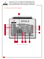
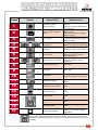
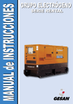
1
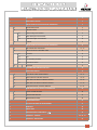
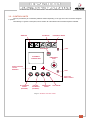
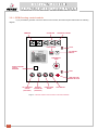
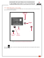
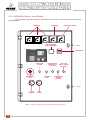
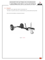
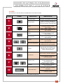
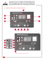
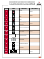
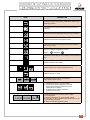
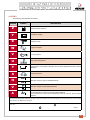
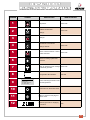
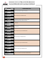
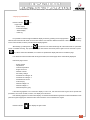
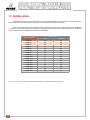
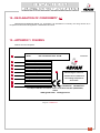
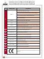
1
WELCOME
2
2
BASIC SAFETY RULES
3
3
INSTALLATION OF THE ELECTRICAL GENERATOR
4
3.1
SOUND INSULATION
6
3.2
CONTROL UNITS
7
3.2.1
GPM-2 Analog Control Module
8
3.2.2
DEEP SEA Digital Control Module
9
3.2.3
INTELIGEN Digital Control Module
10
TRAILER
11
INSTALLATION OF THE ELECTRICAL GENERATOR
12
3.3
4
4.1
UNLOADING AND TRANSPORT
4.2
INSTALLATION OF PORTABLE UNITS
14
4.2.1
Placement
14
4.2.2
Fuel
14
4.2.3
Prior to Starting Generator
14
4.2.4
Electrical Connection
14
STORAGE
15
5
STARTING AND STOPPING THE UNIT
15
6
OPERATION MANUAL
16
4.3
12 - 13
6.1
ELECTRICAL PANEL COMPONENTS
16 - 17
6.2
GPM-2 ANALOG CONTROL MODULE
18 - 22
6.3
DEEP SEA 5210 DIGITAL CONTROL MODULE
23 - 30
6.4
DEEP SEA 5310 DIGITAL CONTROL MODULE
31 - 40
6.5
INTELIGEN DIGITAL CONTROL MODULE
41 - 44
7
MAINTENANCE OF ELECTRICAL GENERATOR
45
7.1
PRIOR TO MAINTENANCE
45
7.2
DURING MAINTENANCE
45
7.3
MAINTENANCE CHART
46
8
TROUBLESHOOTING
47
9
PROTECTION FROM THE ENVIRONMENT
47
10
WARRANTY
48
11
NOISE LEVEL
49
12
DECLARATION OF CONFORMITY
49
13
APPENDIX 1: FIGURES
14
APPENDIX 2: IMAGE INDEX
49 - 50 - 51
52
1
1.- 1 WELCOME
Thank you for purchasing a GESAN electrical generator.
The purpose of this manual is to familiarize the user on how to use and work
with the electrical generator, its components and maintenance.
We recommend carefully reading the manual prior to working with the
equipment in order to ensure proper use.
Save this manual for future reference and if you ever decide to sell the
electrical generator, be sure to include the manual along with the unit.
The following is a general description of the unit and the necessary information
for installation, operation and preventive maintenance.
Additionally, you should have received a specific user manual for the engine
and alternator, electrical setup and a set of keys.
Should you have any problem with the equipment provided, please contact
the distributor directly.
GRUPOS ELECTRÓGENOS GESAN, S.A., as a part of its dedication
to constant product improvement, will revise its manuals and incorporate the
improvements made to supplied units. Thus the information contained in this
document is subject to change without prior notice and without obligation to
update.
2
2.- BASIC SAFETY RULES
Safety precautions and recommendations for handling the electrical generator supplied by GESAN.
1) Do not allow the unit to be used by non-authorized personnel or by minors without adult supervision.
2) Use the necessary Individual protection equipment.
3) Ground the machine.
4) Make sure there is sufficient lighting on the control panel.
5) Do not install the open-skid electrical generator outdoors: risk of electrocution and inoperability.
6) The connection should be made by a qualified electrician in accordance with current norms and regulations. An
improper connection can cause electrical feedback with electrocution hazards for anyone working with the mains
power supply.
7) The supply line between the electrical generator and the consumers should be protected by means of a circuit
breaker for protection against earth leakage (ELCB).
8) Do not operate the unit with the doors open. Risk of electrocution, burns or entrapment.
9) The exhaust system produces enough heat to ignite certain materials.
10) Do not inhale exhaust gases produced by the unit.
11) Do not touch the engine nor the exhaust while the electrical generator is operating as this could produce severe
burns.
12) Ensure proper ventilation in the area where the generator is installed in order to guarantee sufficient flow of coolant
air.
13) Do not refuel while the engine is running or in poorly ventilated areas.
14) Know how to stop the unit in case of emergency.
15) The fuel used is flammable and volatile.
16) Do not overfill the tank and make sure it is closed properly after filling. Use extreme precaution if fuel is spilled: the
vapors and the fuel itself are flammable. Clean the area completely before starting up the unit.
17) Do not smoke or bring any flames or sparks in the vicinity of the electrical generator: risk of explosion.
18) If you notice abnormal behavior by the electrical generator, stop the unit and locate, examine and resolve the
potential failure of the unit prior to restarting.
19) Keep the unit at least one meter away from buildings or other units.
20) Be cautious when switching or installing batteries as they contain acids which are highly hazardous. Avoid spills and
use protection to avoid contact with the skin and eyes. In case of contact, rinse thoroughly with water and contact a
doctor immediately.
21) In case of ingestion of battery acid, drink large amounts of water and milk and contact a doctor immediately.
22) Use only distilled water in the battery: tap water reduces its life cycle.
23) If a battery is filled above the maximum level, the electrolytes will spill out; if this happens, clean the area quickly to
avoid corrosion of the parts it has come in contact with.
24) Frequently clean the unit to avoid obstructions or the entry of foreign elements into the unit (dust, moisture, etc.).
25) Regularly inspect the unit’s electrical cords.
26) Prolonged contact with the used oil can cause skin cancer. Wash your hands after working with the generator.
27) Avoid oil spills on both the inside and outside of the generator. In case of an oil spill on the inside of the unit, clean it
properly as it could potentially become a flammable material.
3
3.- INSTALLATION OF THE ELECTRICAL GENERATOR
General overview of the electrical generator and its different configurations manufactured by GRUPOS
ELECTRÓGENOS GESAN, S.A.
Note: this image corresponds to the detailed view of Image 2
Image 1- ELECTRICAL GENERATOR WITH CANOPY AND OPTIONAL TRAILER FOR UNITS WITHOUT DRIP PAN.
4
8
9
1
10
2
3
11
13
5
12
14
4
15
6
7
16
17
Image 2 - DETAILED VIEW OF IMAGE 1
1) Coolant tank hatch
2) Side access door
3) Fuel tank cap
4) Smoke exhaust
9) Electrical panel door
10) Ventilation grill
11) Lifting frame and eyebolt
12) Electrical control panel
13) Alternator
5) Engine
14) Electrical power panel
6) Antivibration feet
15) Battery
7) Base frame
16) Fuel tank
8) Capot
17) Retention bath
5
3.1.- SOUND INSULATION
The supplied unit is soundproofed and includes sound-insulating canopy. See details on part 11
Image 3 - INTERIOR OF A SOUNDPROOFED ELECTRICAL GENERATOR
6
3.2 .- CONTROL UNITS
The unit provided may be controlled by different modules depending on the type of function it has been designed
to perform.
The following is a generic control panel, which contains all of the electrical and mechanical options available.
AMMETER
VOLTMETER
A
A
A
FREQUENCY METER
V
Hz
HOUR METER
AUTOMATIC
CONTROL UNIT
LOCK
EMERGENCY
STOP
EARTH LEAKAGE
CIRCUIT
BREAKER
LOCK
AUTO FUEL
REFILL SWITCH
OIL PRESSURE
GAUGE
(OPTIONAL)
BATTERY
VOLTMETER
(OPTIONAL)
ENGINE TEMP.
GAUGE
FUEL GAUGE
Image 4 - GENERIC CONTROL PANEL
7
3.2.1.- GPM-2 analog control module
diagram:
If you purchased a generator unit with a GPM-2 control module, the electrical panel will look like the following
AMMETER
A
VOLTMETER
A
A
V
FREQUENCY METER
Hz
HOUR METER
LOCK
VOLTMETER
SWITCH
EMERGENCY
STOP
EARTH LEAKAGE
CIRCUIT
BREAKER
LOCK
TEMP AND FUEL
GAUGE BUTTON
OIL PRESSURE
GAUGE
(OPTIONAL)
BATTERY
VOLTMETER
(OPTIONAL)
ENGINE TEMP.
GAUGE
FUEL GAUGE
Image 5 - CONTROL PANEL FOR THE GPM-2 CONTROL MODULE
8
3.2.2.- DEEP SEA digital control module
If you purchased a generator unit with a DEEP SEA control module (models 5210 and 5310), the electrical
panel will look like the following diagram:
ENGINE BLOCK
HEATER LIGHT
(YELLOW)
EMERGENCY
STOP
ELDON
XXXXXX
DIAGNOSTIC
BUTTON
LOCK
EARTH LEAKAGE
CIRCUIT
BREAKER
AMMETER
BATTERY
VOLTMETER
Image 6 - CONTROL PANEL FOR THE DEEP SEA CONTROL MODULE
Note: The
button on the control module performs the same function as the diagnostic button (while in
OFF/AUTO mode).
9
3.2.3.- INTELIGEN Digital Control Module
If you purchased a generator unit with an INTELIGEN control module, the electrical panel will look like the
following diagram:
AMMETER
A
A
FREQUENCY METER
VOLTMETER
A
V
Hz
EARTH LEAKAGE
CIRCUIT BREAKER
LOCK
HOUR METER
GREEN FUEL
BUTTON
ENGINE BLOCK
HEATER PILOT
(YELLOW)
ON: GREEN
LIGHT
EMERGENCY
STOP
AUTO FUEL
REFILL SWITCH
(OPTIONAL)
SLAVE/MASTER
SWITCH
(OPTIONAL)
LOCK
LOAD
AMMETER
FUEL
GAUGE
Image 7 - CONTROL PANEL FOR THE INTELIGEN CONTROL MODULE
10
3.3 .- TRAILER
The generator can be supplied with a trailer for transporting the unit.
• Site Trailer: for private-use areas only. Includes DIN hitch ring, safety brake and jockey wheel.
* Note: Ask about the possibility of using trailer with drip pan.
Image 8 - TRAILER
11
4.- INSTALLATION OF THE ELECTRICAL GENERATOR
4.1 .- UNLOADING AND TRANSPORT
The unloading and transport of the unit should only be done by qualified personnel, observing certain minimum
safety conditions.
• The ground must be capable of supporting the full weight of the Generator and the forklift.
• Make sure that the battery is disconnected.
• Make sure that the fuel tank is empty.
• Place the open arms of the forklift below the chassis at an equal distance with respect to the lifting frame.
• With a hoist, raise the unit using the lifting frame eyebolt.
The image below shows a generator unit that which includes a frame with a single lifting point.
Image 9 - LIFTING FRAME
12
If your unit includes a trailer, one of the following may apply:
• Trailer 1 - Site trailer: Connected with a DIN hitch ring and safety chains to the rear of the towing vehicle. Use of
this trailer is not authorized on public roads. Use the safety brake whenever necessary.
• Trailer 2 - Road trailer: Keep in mind the legal considerations detailed in point 3.3.
Always perform the following precautionary steps:
• Make sure the hitch ring and coupling connecting the towing vehicle to the trailer have the adequate towing capacity
supporting a weight equal to or greater than the gross trailer weight.
• Make sure there is no wear or damage to the hitch system or coupling; never tow the generator if there is excessive
wear or if any piece is damaged.
• Make sure the coupling is properly fastened to the towing vehicle.
• Check the condition of the trailer’s tires.
• Connect the safety cable to the bumper or rear part of the towing vehicle; never attach it to the generator unit or
to the hitch ring itself.
• Check to make sure the brake systems on both the trailer and towing vehicle are in perfect condition.
• Make sure the trailer’s turn signal indicators and brake lights are correctly installed and functioning properly.
• After each transport, apply a light coat of grease to both the towing vehicle’s coupling and the trailer’s hitch ring.
before towing again.
• Install safety chains on units with site trailer.
13
4.2 .- INSTALLATION OF PORTABLE UNITS
Portable units are defined as those moved to different work sites at least twice yearly.
4.2.1.- Placement
This type of unit must be installed in well ventilated areas in order to ensure sufficient flow of coolant air and
preventing combustion smoke from sitting in the engine’s exhaust.
The unit must be placed in a location that can safely bear the full weight of the generator unit and guarantee its
stability both horizontally and vertically.
It should always remain at a distance that allows access to the interior of the electrical generator (at least 1 meter
away from any building or wall).
Avoid installing in areas with moisture or locations where water could get into the interior of the unit.
* Note: Exhaust can be supplied with optional spark arrester in the exhaust tube for Ex zones.
4.2.2.- Fuel
As diesel fuel is used, keep in mind the safety instructions previously mentioned in point 2 - BASIC SAFETY
RULES.
Before operating, check the fuel level to ensure that the tank has the amount needed by the generator unit for an
entire work day.
There is a optional of quick conectors for external fuel tank. We can connect them with conductors through canopy
fuel point for replenishing the generator base tank.
You should consider this series of points:
1) In order to connect or disconnect, you should move backwards the female lock fitting.
2) Make sure that the external tank aspiration circuit does not contain air.
3) In the external tank, the aspiration connector should be male and the return connector female, both are 3/8
BSP connectors.
4) Return should be correctly connected.
5) Connectors have to be watertight; they lock when they are disconnected.
6) The distance between tank and genset has to be as shorter as possible. If you observe engine anomalous
behaviour (lack of power for aspiration problems), you should have to reduce distance or increase the hose diameter.
4.2.3.- Prior to starting generator
Before starting up the generator, inspect the consumer power supply conductors to make sure they are in perfect
condition and that the consumers are disconnected; the unit should always be started up at no load.
Make sure that there is nothing obstructing the ventilation ducts and that there are no foreign objects inside the unit.
Make sure the fluid levels of the electrical generator are adequate for the service the unit will be providing and that
there are no leaks or spillage.
4.2.4.- Electrical connection
The connecting of cables that supply consumers must be performed by qualified personnel; these conductors should
be connected to terminals U V W and N or L1 L2 L3 and N or to the socket panels.
The four-pole circuit breakers have copper bus bars to facilitate the connection with conductors and prevent
deterioration produced by repeated connecting.
Depending on the options selected, sockets may or may not have individual protection, which is distinguished from
the general unit protection by the use of an individual circuit breaker for each socket.
14
4.3.- STORAGE
If you think your generator will be inactive for a long period of time, follow these instructions:
1) Press STOP on the control module.
2) Press the emergency stop button to avoid future involuntary startups when connecting.
3) Empty the fuel tank. Make sure the internal protection valve is in the correct position.
4) Leave the battery disconnected.
5) Avoid storing the unit in areas with high dust accumulation or excessive moisture.
6) Do not use pressurized water when cleaning the unit.
7) Check your engine manual for care instructions; the manual has been provided along with this booklet.
8) For alternator care instructions, please check your alternator’s manual, which has been provided along with
the document you are now reading.
5.- STARTING AND STOPPING THE UNIT
To start up the electrical generator, follow the steps listed below:
1) Check the levels of oil, coolant and fuel.
2) Close the battery isolator.
3) Release the emergency shutoff switch if it has been pressed.
4) Check the electrical generator’s automatic switch (levers should be in the lowered position).
5) To perform the startup of your electrical generator, please refer to point 6 - OPERATION MANUAL, taking
into account the control panel model of your unit.
6) Once the unit has been started, connect the electrical generator’s automatic switch.
7) Make sure the earth leakage circuit breaker (ELCB) is functioning properly by pressing the TEST button.
8) Turn on the electromagnetic circuit breaker once again and use the electrical generator normally.
To stop the unit:
1) Disconnect the loads.
2) Turn off the electromagnetic circuit breaker.
3) Leave the engine running at no load for 2 minutes to cool down the generator unit.
4) Stop the engine completely by switching the control module switch to the OFF position.
15
6.- OPERATION MANUAL
The generator you purchased has been designed for manual service and thus starting and stopping the unit will be
done manually.
The following is a description of the different elements, according to the electrical generator chosen.
6.1.- ELECTRICAL PANEL COMPONENTS
A
AMMETER:
Measures the Intensity (A), by means of a switch, of the different phases of the electrical generator.
Hz
FREQUENCY METER:
Indicates the Frequency of the electrical generator (Hz).
V
VOLTMETER WITH ATS:
Indicates the Voltage (V), by means of a switch, of the different phases of the electrical generator.
HORAS
16
HOUR METER:
ndicates number of hours worked by the electrical generator.
The two digits in red on the right indicate hundredths of hours. Hours are indicated in white from the third
digit on.
EMERGENCY STOP BUTTON:
Pressing this button brings the electrical generator to an immediate stop. To cancel, turn to the left, when the
end of the emergency situation has been confirmed.
On soundproofed units the emergency stop button is installed apart from the electrical panel (built into the
canopy).
GAUGES INDICATING ENGINE PARAMETERS:
Oil pressure.
Intensity of battery voltage.
Engine temperature.
Fuel level.
DIAGNOSTIC BUTTON:
Allows engine parameters to be checked when electrical generator is stopped (electronically controlled
engines). Also gives a readout of the generator’s different alarms.
EARTH LEAKAGE CIRCUIT BREAKER (ELCB):
Protection against earth leakage of one phase, setting off the electrical generator’s primary protection switch.
Configured to be activated when voltage is exceeded by 3 mA, with a time delay of 0s.
Includes a TEST button for checking the state of the ELCB.
It is the installer’s responsibility to adjust and seal the ELCB according to the current regulations.
17
6.2.- GPM-2 ANALOG CONTROL MODULE
15
1
2
8
3
9
4
10
5
11
6
7
17
16
14
13
Image 10 - GPM-2 CONTROL MODULE
18
12
NUMBER
SYMBOL
DESCRIPTION
IDENTIFICATION
Flashing red light: three failed startup
attempts.
Continuous red light: voltage failure
or low frequency.
Flashing red light: battery charge
alternator failure .
Continuous red light (unit stopped):
indicates contact.
Flashing red light: low oil level.
Continuous red light (unit stopped):
indicates contact.
1
Unit startup failure /
alternator failure.
2
Battery charge alternator
failure.
3
Low oil level.
4
Low level / high coolant
temperature.
Flashing red light: high temperature.
Continuous red light: low coolant level.
5
Overload.
Flashing red light: unit overload.
6
Low fuel level.
7
Emergency stop / overspeed.
8
AUTO
TEST
Red: low fuel level.
(Continuous/flashing red light:
stopped/warning).
Flashing red light: emergency stop.
Continuous red light: engine
overspeed.
Remote startup mode.
Green LED.
Unit heating.
Yellow LED.
Stop signal.
Flashing red light: imminent stoppage.
Continuous red light: stop command.
11
Maintenance signal.
Flashing blue: see maintenance
section.
12
Maintenance reset button.
Button.
13
Unit startup button.
Button.
Manual mode.
MAN
15
Key position for stopping
unit.
STOP
16
Automatic mode.
AUTO
17
Programmable alarm.
Flashing or continuous red light;
user-defined.
9
10
14
STOP
Fuel
The GPM-2 control module has three positions: STOP, automatic (AUTO) and manual
(MAN). Key selectable (numbers 14 through 16 of the descriptive chart for the control
module).
19
•
Startup:
When the key is turned to Manual Mode position, LED indicators for low oil level
alternator
(2)), and preheating
will be turned off, at which point the START button
(3), battery charge
(9) will be turned on and after 10 seconds the LED indicator (9)
(13) can be pressed to start up the unit.
Follow the instructions detailed in point 5 - STARTING AND STOPPING THE UNIT.
Note: While the key is in the MAN position, if the button (13) is not pressed within 20 seconds the control module
will shut down the system.
•
Stopping the unit:
Follow the instructions detailed in point 5 - STARTING AND STOPPING THE UNIT.
Turn the key to the central STOP position.
INDICATOR LIGHTS:
AUTO
TEST
Indicates remote startup; continuous green light turns on when unit is operating remotely.
8
Indicates heating of the unit; continuous yellow light turns on when unit is being heated. Wait
before starting up the unit.
9
STOP
10
Indicates stop signal.
Flashing: Indicates engine cooling period.
Continuous: The control module issues a stop command to the engine; stays lit for 20 seconds
following the complete stopping of the engine.
Indicates maintenance; flashing light; the first time the light turns on after 50 operating hours and
afterwards every 150 hours.
11
To reset the maintenance hour meter, the electrical generator must be running. Turn the key to
the STOP position while pressing the button
completely deactivated.
20
(12) until the control module becomes
ALARMS:
The following is a chart describing the possible alarms of the GPM-2 module:
NUMBER
SYMBOL
DESCRIPTION
Unit startup failure.
1
2
3
4
5
6
7
Alternator failure.
Contact.
Battery charge alternator
failure.
Contact.
Low oil pressure.
Low level.
High coolant temperature.
Overload.
If the light is flashing, an audible signal
will be given and generator is shut down.
If light is continuous, indicates low
frequency. If it runs below nominal level
for over 30 seconds, unit is shut down.
If light is continuous and the engine
is stopped, indicates “contact”
(not an alarm).
If light is flashing, indicates failure
and the control module issues unit
stop command.
If light is continuous and the engine
is stopped, indicates “contact”
(not an alarm).
If light is flashing, indicates failure
and the control module issues unit
stop command.
If light is continuous, indicates low
coolant level and module issues unit
stop command.
If light is flashing, indicates high
coolant temperature and the control
module issues unit stop command.
Light will flash and indicate that the
protection switch is open; module
issues unit stop command.
If light is flashing, indicates WARNING.
Low fuel level.
Emergency stop.
Overspeed.
17
IDENTIFICATION
Programmable alarm.
If light is flashing, module issues
unit stop command.
If light is continuous, module issues
unit stop command, indicating
an emergency stop
(emergency button activated).
If the light is flashing, module issues
unit stop command, indicating
engine high speed.
If the light is continuous, indicates
WARNING.
If light is flashing, module issues
unit stop command.
Note: If at any point 3 or more LED indicators turn on, it could indicate low battery level.
21
6.3.- DEEP SEA 5210 DIGITAL CONTROL MODULE
8
9
7
10
6
11
1
2
3
4
5
Image 11 - DEEP SEA 5210 CONTROL MODULE
Z
V
Y
U
X
T
W
S
11
Image 12 - DEEP SEA 5210 CONTROL MODULE
22
NUMBER
1
2
3
4
SYMBOL
DESCRIPTION
IDENTIFICATION
Stop button.
Control module connection.
MANUAL mode button.
Settings -
Green LED
Green LED
Settings +
AUTOMATIC mode button.
Settings: ENTER.
Green LED
5
Startup button for Electrical generator.
6
When lit, indicates correct readings for
Green LED
electrical generator.
7
Configurable LED indicators.
8
Screen indicating the status of the
electrical generator.
9
Down button on the screen menu.
10
Event Log button.
11
LED lit: Electrical generator is supplying
Green LED
consumers.
23
•
Startup:
If the LCD screen is off, press
Press the button
operating. Press
(1) to connect the control module and the LCD screen will turn on.
(2) and the LED in the top part of the button will turn on, indicating that the unit is
(5) briefly to start up the unit.
Follow the instructions detailed in point 5 - STARTING AND STOPPING THE UNIT.
There is a maximum of 3 startup attempts, after which the flashing stop symbol
the startup failure indicator
will be displayed along with
.
The status screen of the Deep Sea 5210 Control Module will indicate all of the possible events of the electrical
generator.
This image shows all of the symbols displayed on the LCD screen (8).
kW kVAr CosØ
The LCD display (8) will normally look similar to this:
Example of the screen indicating the voltage readings for each phase of the electrical generator.
L1L2L3-
•
229.2
N 231.5
N 235.7
N
V
V
V
Stopping the unit:
Follow the instructions detailed in point 5 - STARTING AND STOPPING THE UNIT.
Press
24
(1) to stop the unit. The unit will be stopped immediately.
ICON
DESCRIPTION
Indicates that the screen display information refers to the
electrical generator.
Indicates that the event log reading is being accessed
(Flashing).
Indicates that the programming mode is being accessed.
Indicates that the electrical generator is idle.
Indicates that the electrical generator’s system date and
time is being shown.
This icon indicates a stoppage or alarm;
Warning =
, Stoppage =
Indicates the percentage of fuel remaining in the generator’s
tank.
Indication related to the battery.
Indicate battery level outside established limits.
Indicates keypad is locked.
kW and kVAr indicate units of current power.
CosØ: Indicates power factor.
º C:
º F:
~ :
V :
A :
....:
Bar Rpm
psi Hz
Kpa
L1-L2N L2-L3N L3-L1N
Measurement given in degrees celsius.
Measurement given in degrees Fahrenheit.
Measurement related to alternating current.
Measurement of voltage.
Measurement of Intensity (amperes).
Indicates direct current.
If Lx-Lx is displayed:
Indicates measurement of phase-phase voltage.
If Lx-N is displayed:
Indicates measurement of phase-neutral voltage.
Bar, rpm, PSI, Hz, kPa: indicate measurement units for the
corresponding parameter.
The lock icon indicates keypad is locked.
25
To view the different parameter readings, press
following order:
-
, and the LCD indicator (8) will display these readings in the
RPM of generator / frequency (Hz).
Line-Neutral AC voltage of generator.
Line-Line AC voltage of generator.
Oil pressure.
Coolant temperature.
Fuel level (%).
Engine operating hours.
DC voltage of battery.
AC line current.
Total kW.
Voltage (V).
Phase angle (cos).
The following is an example of what the LCD screen (8) will look like when the various parameters are displayed:
SCREEN SEQUENCE
Rpm
Hz
L1- N
L2- N
L3- N
L1- L2
L2- L3
L3- L1
Pressing
1 500
50.0
DESCRIPTION
Initial screen in which engine speed and generator frequency are
measured.
To measure the next parameter, press
229.2
231.5
235.7
Then the second measurement screen appears, indicating the
voltage readings between each phase and neutral.
To measure the next parameter, press
397.0
401.0
408.3
The third measurement screen will appear, indicating the voltage
readings between phases.
To measure the next parameter, press
afterwards, we move from one parameter to the next in the order specified on the previous page.
WARNING/STOPPAGE
DESCRIPTION
Turns on to indicate a set alarm; displayed along with the icons
detailed on the preceding page.
Warning state =
; Stoppage =
LCD screen will appear as follows when a configurable alarm is
activated.
26
ALARMS:
The following chart describes each alarm:
NUMBER
SYMBOL
DESCRIPTION
Z
Fuel level below minimum.
Y
Low battery voltage.
X
Emergency stop.
W
Engine overspeed.
V
Low oil pressure.
U
High engine temperature.
T
If engine does not start after 3 attempts, the unit will be stopped and this icon will be
displayed.
S
Low engine speed.
H
Hz
Hz
Alternator frequency beyond established limits.
V
Alternator voltage beyond established limits.
A
If it is detected that the generator’s output current exceeds the established value for
an extended period of time, this warning will be displayed.
If the cutoff point for overcurrent is exceeded by 10% for one hour, the unit will be
stopped.
A
Note: If the established limits defined as warning or stop are exceeded, the module will display the corresponding alarm. None of these
will be shown if not detected by the system.
Note: The
ashing.
27
- Event log:
To view the event log, press the following button repeatedly
This icon will flash
(10).
.
A screen similar to this will be shown:
2002
11.01
8.17
“On november 1, 2002, at 08:17, the system detected that the oil pressure was below the minimum level and shut
down the generator.”
To move from one event to the next, press
To exit the main screen, press
(9).
(10).
Note: Warning alarms are not logged.
- Adjust date and time:
The date and time are adjustable. When the battery is disconnected, the date and time are frozen; when the
battery is reconnected, the date and time shown will be from the time the battery was disconnected.
The date and time reflected in the event Log will be taken from the configuration according to the following
steps:
Press
(1) and
(10) simultaneously. This icon
mode” is active. The calendar will be shown.
Press
(4) and the hour will start flashing.
To adjust to the desired setting, press
Once the desired value has been set, press
28
(3) or
(2).
(4) to save.
will flash, indicating that “configuration
LIST OF POSSIBLE ALARMS:
1
Low pressure
16
Energize to stop
2
High temperature
17
Low voltage
3
Fuel level (%)
18
High voltage
4
Date / time
19
Low frequency
5
Mains transient delay
20
High frequency
6
Start delay
21
Generator under voltage L1-N
7
Warming up
22
Generator over voltage
8
Crank attempt
23
Generator under frequency
9
Crank rest
24
Generator over frequency
10
Safety delay
25
Delayed overcurrent %
11
Overspeed overshoot
26
Under speed
12
Warming up
27
Over speed
13
Transfer delay
28
Low voltage
14
Return delay
29
High voltage
15
Cooling run
30
Alternator failure
29
6.4.- DEEP SEA 5310 DIGITAL CONTROL MODULE
9
10
RUNNING
RUNNINGIN
INAUTO
AUTO
8
Warming
Warming10s
10s
L-N
L-N 240V
240V DA
DA 50Hz
50Hz
L-L
L-L 415V
415V OKW
OKW
11
7
12
1
2
3
4
5
Image 13 - DEEP SEA 5310 CONTROL MODULE
30
6
NUMBER
SYMBOL
1
DESCRIPTION
Stop button.
MANUAL mode button.
2
Settings -
3
IDENTIFICATION
Green LED
Green LED
Settings +
4
AUTOMATIC mode button.
5
Button to silence alarms / control
Green LED
module LED test.
6
Button for starting up electrical
generator.
7
When lit, indicates correct readings
Green LED
for electrical generator.
8
Configurable LED indicators.
9
Settings: ENTER.
RUNNING IN AUTO
Warming 10s
L-N 240V DA 50Hz
L-L 415V OKW
Green LED
Red LED
Screen indicating the status of the
electrical generator.
10
Down button on the screen menu.
11
Button to scroll to next page of
screen menu.
12
Electrical generator is supplying
consumers.
LED
31
•
Startup:
If the LCD screen is off, press
Press the button
Press
(1) ) to connect the control module and the LCD screen will turn on.
(2) and the LED in the top part of the button will turn on, indicating that the unit is operating.
(5) to start up the unit.
Follow the instructions detailed in point 5 - STARTING AND STOPPING THE UNIT.
There will be a maximum of 3 startup attempts, after which the information screen will display a startup
alarm:
Alarm
Shutdowm
Failed to start
•
Stopping the unit:
Follow the instructions detailed in point 5 - STARTING AND STOPPING THE UNIT.
Press
32
(1) to stop the unit. The unit will be stopped immediately.
ALARMS:
Press
(5) to silence the audible alarm and the common alarm LED.
By default, the information screen will display the following message:
Running in auto
Generator on load
L-N 230v 240A 50Hz
L-L 400v 133kW
If an alarm occurs, the screen will display the following:
Alarm
Alarm type. Shutdown or warning
Shutdown
High temperature
Alarm Description.
Example: High engine temperature.
The warning alarms do not entail generator unit shutdown.
If shutdown occurs while a warning is active, the screen will cycle through the active alarms:
Alarm
Shutdown
High temperature
Alarm
Warning
Low coolant level
Alarm
Shutdown
Emergency stop
33
INCIDENT
ALARM DESCRIPTIONS
ALARM
Warning
Charge fail
Battery charge alternator voltage not detected.
ALARM
Warning
Low battery volts
ALARM
Battery voltage beyond established limits.
Warning
High battery volts
ALARM
Fail to stop
After shutdown command, engine continues running.
Could also indicate faulty oil pressure sender.
ALARM
Warning
Low fuel level
Low fuel level.
ALARM
Warning
Low oil pressure
Low oil pressure.
ALARM
Warning
High temperature
ALARM
Engine temperature beyond established limits.
Warning
Low coolant temperature
ALARM
Avertissement
Overspeed
ALARM
Engine speed beyond established limits.
Warning
Underspeed
ALARM
Warning
Over frequency
ALARM
Alternator frequency beyond established limits.
Warning
Under frequency
ALARM
Warning
AC overvolts
ALARM
Alternator voltage beyond established limits.
Warning
AC undervolts
ALARM
Warning
High current
34
Intensity of the alternator output beyond established limits.
INCIDENT
DESCRIPTION OF SHUTDOWNS
ALARME
Shutdown
Failed to start
ALARME
Shutdown
Emergency stop
Engine does not start, three attempts made.
Controlled shutdown of the unit. It will not be functional until the emergency stop button
has been reset.
ALARME
Shutdown
Low oil pressure
Low oil pressure.
ALARME
Shutdown
High temperature
High engine temperature.
ALARME
Shutdown
Overspeed
ALARME
Engine speed beyond established limits.
Shutdown
Underspeed
ALARME
Shutdown
Over frequency
ALARME
Alternator frequency beyond established limits.
Shutdown
Under frequency
ALARME
Shutdown
AC overvolts
ALARME
Alternator voltage beyond established limit.
Shutdown
AC undervolts
ALARME
Shutdown
Oil pressure sender fault
Faulty oil pressure sender.
ALARME
Shutdown
High current trip
Intensity of the alternator output beyond established limits.
Note: If the established limit for shutdown is exceeded, a corresponding alarm screen will be displayed and on the configurable
LED indicator (8) the common shutdown alarm will appear.
35
- Typical information screen messages:
Running in auto
Generator on load
L-N 230V 240A 50Hz
L-L 440V 133kW
Indicates electrical generator running normally in automatic mode. Also indicates the
average line to neutral voltage (L-N), the highest of the three phase currents, the
nominal frequency, average line-to-line voltage (L-L) and total kilowatts.
- Measurement parameter display screens:
Coolant temperature
Coolant temperature in degrees (ºC) Celsius and degrees Fahrenheit (ºF).
60 ºC 140 ºF
Oil pressure
Displays engine oil pressure in Bar, PSI and kPa.
6 Bar 87 PSI
600 kPa
Generatos amps
All three generator line currents.
L1 L2 L3
238 241 241
- Event Log:
To view the event log, press the following button repeatedly
(11).
Register of shutdown alarms occurring in the generator unit; the most recent occurrences can be stored. A screen
similar to this is shown:
Event log 21:15:00
10 september 2003
Low oil pressure
Shutdown
“On September 10, 2003, at 21:15, the system detected that the oil pressure was below the minimum level and shut
down the generator”.
To scroll from one event to the next, press
To exit the main screen, press
Note: Warning alarms are not logged.
36
(11).
(10).
- Displaying information:
Press this button:
(11).
Page order:
- Status display.
- Instrument display.
-
Alarms display.
-
Event log.
It is possible to scroll through the different display screens by pressing the next page button:
(10). Once
selected, the instrument will remain on the screen until the user selects a different instrument or after a period of inactivity
for the control module, at which point the default display appears.
Alternatively, by holding down on
(10) the user can autoscroll through all of the instruments on a particular
screen. To disable scrolling, stop pressing the page down button then either press it again for a few seconds or press
(11). When autoscroll is disabled, if no buttons are pressed the display will return to the alarms page.
If an alarm becomes activated while viewing instruments, the alarms page will be automatically displayed.
Instrument page content:
- Engine speed.
- Oil pressure.
- Coolant temperature.
- Engine hours run.
- Number of starts.
- DC battery voltage.
- Generator AC voltage L-N.
- Generator AC voltage L-L.
- Generator line current.
- Fuel level (%).
- Nominal voltage L-N.
- Nominal voltage L-L.
- Nominal frequency (Hz).
If the following appears in an instrument display: # # # # # # , this means that the engine cannot provide this
parameter; the control module, however, can display this instrument.
If the following appears in an instrument display: # # # # # # with the electrical generator in OFF/AUTOMATIC mode
(with the engine stopped), this means that the control module is not connected to the engine.
Press this button
(6) to display the given value.
37
- Alarm LED:
Remote start on load
Overload pre-alarm
Common
Common
- Editing the current date and time:
The date and time are adjustable. When the battery is disconnected, the date and time are frozen; when the battery
is reconnected, the date and time shown will be from the time the battery was disconnected.
The date and time reflected in the event Log will be taken from the configuration according to the following stepst:
Press
(1) and
(11) ) simultaneously, then enter the correct PIN number.
Press
(3) until the date and time screen appears.
When Date and Time screen appears, press the
Press
(3) or
Press the
(2)
38
button (4). The minutes will start to flash.
(2) to adjust to the desired setting.
(10) button to confirm the value entered. The hour will begin to flash. Press
again to adjust to the desired setting.
(3) or
Press the
Press
Press the
Press
button (10) to confirm the value entered and select the day. The day will begin to flash.
(3) or
(2) again to adjust to the desired setting.
(10) button to confirm the selection made and select the month. The value will start to flash.
(3) or
(2) again to adjust the month.
Lastly, set the correct year by pressing the
(10) button. The year will start to flash. Press
(3) or
(2) pour régler la valeur désirée.
Press
(4) to save the changes made to date and time.
The screen will display the date and time
Date and time
19 sep 2003 10:00
entered.
39
6.5.- INTELIGEN DIGITAL CONTROL MODULE
1
2
4
3
5
18
6
7
17
8
16
15
14 13
12
11
Image 14 - INTELIGEN CONTROL MODULE
40
10
9
NUMBER
SYMBOL
1
2
Horn
reset
3
4
Fault
reset
IDENTIFICATION
Deactivates audible alarm.
Mode
Mode
DESCRIPTION
Scrolls through different operating
modes.
Fault reset.
OFF←MAN←AUT←TEST
OFF→MAN→AUT→TEST
Acknowledges faults and alarms.
5
Start
I
Start button.
In manual mode.
6
Stop
0
Stop button.
In manual mode.
7
Generator voltage present.
8
Electrical generator failure.
9
State of GCB.
Green if unit voltage is present
and within limits.
Flashes during synchronization with mains.
Flashing Red LED indicates alarm.
Green when GCB is closed.
Flashes during synchronization with mains.
10
GCB on/off.
Opens and closes GCB in manual mode.
11
State of MCB.
Green is MCB is closed. Flashes during
synchronization with mains.
12
MCB on/off.
13
State of mains power.
14
State of voltage supplied to
consumers.
15
Enter
16
Red light flashes if mains failure occurs
and generator stops; continuous if
generator is operating, turns off
when mains power restored.
Confirms on-screen value.
Increases value.
Selects on-screen value.
17
18
Enter button.
Green if mains power is correct.
Increases value.
Page
Button to cycle through the
menus.
Cycles through display screens.
→MEASUREMENT
→ADJUSTEMENT
→HISTORY
41
The InteliGen module contains the following three menu screens:
- Measurement
Page
- Adjustment
Can be selected using the following button
(18).
- History
To display the different instruments on each screen menu, press
(17) and
(16).
The measurement screen displays the parameters measured by the engine; if the engine uses an electronic
management system, many additional parameters can be displayed. In addition to these parameters, measurements
can be displayed for fuel level, oil pressure, current, voltage, frequency, run hours and battery charge level.
The adjustment menu screen displays the adjustment parameters already configured; it is not necessary to edit any
of these.
The history screen menu displays the log of alarms that have occurred in the generator unit. It also logs the opening
and closing of the mains circuit breaker as well as the starting and shutting down of the generator unit.
42
•
Startup:
Press the START button
Start
I
established limits, the LED indicator
(5) to start up the electrical generator. When the generator voltage is within the
(7) will be lit. Next press the GCB ON/OFF button
will be transferred directly to the electrical generator. To stop the unit, press STOP
•
Stop
0
(10). The loads
(6).
LOAD TEST Mode (Manual):
This operating mode is used to allow the electrical generator to check the state of the mains power or to disconnect
from the mains when an imminent mains failure is detected. When this operating mode is selected, the unit starts up at
no load. To transfer the loads to the unit, press the MCB ON/OFF button
button
(12), and then press the GCB ON/OFF
(10). At this time synchronization occurs between the electrical generator and the mains for 60 seconds
to assume the loads.
•
OFF mode:
The electrical generator will not start. Even if we press the buttons START
Start
I
(5), STOP (6), GCB ON/OFF
(10), the generator will not respond.
43
7.- MAINTENANCE OF ELECTRICAL GENERATOR
You must make sure that the person who will perform this duty is qualified to do so and utilizes the appropriate
individual protection equipment.
7.1.- PRIOR TO MAINTENANCE
You must first:
• Switch control module to the STOP position.
• Press the emergency stop button.
• Open the battery isolator.
7.2.- DURING MAINTENANCE
Preventive maintenance tasks are necessary to preserve the unit; doing so will result in optimum performance.
Be sure to verify the following items:
1) While the engine is cold, the oil level should be between the minimum and maximum values. If it is below the minimum,
add engine oil.
Note: With the GPM-2 and InteliGen modules, after running 50 hours notice will be given to change the oil. The recommende
oil is 15W40.
2) radiator water level should be adequate.
3) The fuel level in the tank should be sufficient for the service to be performed. The generator control panel is equipped
with a fuel gauge, which will be functional whenever the electrical panel is receiving power.
4) Always refuel in a well ventilated area with the engine stopped.
5) Closely inspect the connections and the electrical circuit, for both the mechanical and electrical sections.
6) Check carefully for possible liquid leaks. If a leak is detected, find its source and resolve the problem.
7) The air inlet and outlet vents should be completely unobstructed to allow for free circulation of cooling air.
8) Check the battery’s connection terminals and electrolyte level (if necessary, add demineralized or distilled water). Acid
should never be added. The battery should be recharged if the terminal voltage is below 12.3 V.
9) If the battery needs recharging after being taken out of the unit, remove the vent caps and charge battery with direct
current only. Connect the charger’s positive (+) cable to the battery’s positive (+) terminal and the charger’s negative (-) cable
to the battery’s negative (-) terminal. Recharge battery with a current equaling 1/10 the nominal capacity (Ah). Battery is fully
charged when acid density is 1.28. Before completing recharging process: turn off charger before disconnecting battery and
check electrolyte level.
10) If the battery is discharged and you want to perform an emergency startup with the battery from another generator, first
check the tightness of the discharged battery’s terminals. Stop the engines of both units and connect the two positive terminals
of the batteries first and then connect the negative terminal of the charged battery to a metal area on the disabled unit (ground).
Start up the auxiliary unit and then the unit being repaired. Disconnect the cables in reverse order to avoid a short circuit. Finally,
fully charge the battery.
11) Installation of the fuel filter in all units means that the operator must constantly monitor the water buildup and drain
as it becomes filled. This does not entail an inconvenience but rather simply keeping an eye on the transparent tank in order to
know when to drain. If the filter were to become worn out, it should be replaced.
12) The oil draining pump improves the draining process, saves time and facilitates maintenance.
13) The fuel tank includes a drain hatch to provide quick access and a safety valve to prevent fuel from being extracted
through the outlet on the base fra.
14) The radiator is drained through the base frame outlet.
15) For maintaining the canopy, we recommend cleaning periodically to avoid dirt buildup. The unit’s galvanized canopy
prevents corrosion and rust.
Note: While performing preventive maintenance tasks it is advisable to wear protective eyewear and gloves during all
operations involving the handling of battery acid.
Note: Remember to always perform all operations with the utmost precaution and safety as indicated in this Manual.
(Pay special attention to the risk of short circuits that could be caused by coming in contact with the unit’s metallic objects).
44
7.3.- MAINTENANCE CHART
FREQUENCY
MAINTENANCE OPERATION
AFTER 50 HRS.
• Perform 250 hr. maintenance.
DAILY
• Check fuel level on the main tank.
• Check coolant fluid level.
• Check the oil level (see engine’s user manual).
• Drain water separator filter.
• Make sure the radiator inlets and outlets are unobstructed.
• Inspect the air filter service indicator.
• Make sure the electrical generator’s outlet cables are in perfect condition.
• Make sure machine is properly grounded and that the earth leakage circuit breaker is working
(press test button).
• Perform a general inspection and make sure there are no fluid leaks.
• Check the engine manufacturer’s manual for specific tasks.
EVERY 50 HRS. /
WEEKLY
• Water and sediment in fuel tank: Drain.
• Review the connections of the startup battery, clean and cover with vaseline.
• Change the filtering element of the water separator filter.
EVERY 250 HRS. • Start up the engine 3 times, noting the voltage readings each time. Make sure battery voltage is
EVERY 6 MONTHS correct on each startup.
• Make sure all of the electrical panel lights are functioning properly.
• Check the state of all of the gauges and indicators on the electrical panel.
• Clean the interior of the electrical generator. *
• Check the engine manufacturer’s manual for specific tasks.
EVERY 500 HRS.
YEARLY
• Make sure there are no leaks in the coolant tubes.
• Make sure that all of the unit’s alarms display correctly.
• Thoroughly clean the engine radiator.
• Check the engine manufacturer’s manual for specific tasks.
• Fully charge the battery and check the electrolyte level.
• Thoroughly clean the generator unit.
• Clean the control panel and tighten its connections.
EVERY 1000 HRS. • Clean the electrical power panel and socket panel and tighten its connections.
YEARLY
• Make sure the control apparatus measurements given are correct.
• For units with trailer, take to specialized maintenance shop (annually).
• Check the alternator manufacturer’s manual for specific tasks.
• Check the engine manufacturer’s manual for specific tasks.
• Check the condition and tightness of the antivibration feet.
EVERY 3000 HRS.
• Change coolant (does not apply to the oil cooled DZR range).
EVERY 2 YRS.
Notes:
• Check your engine and alternator manuals for specific maintenance tasks.
• Make sure maintenance is performed by qualified personnel.
• Be sure to comply with local legislation on environmental protection. Batteries, filters and used fluids as well as replaced electrical
material and packaging should be taken to an authorized recycling center.
* When cleaning the generator, do not use pressurized water as it could damage components.
45
8.- TROUBLESHOOTING
Engine does not start
Engine starts
IN THE ELECTRICAL PANEL
INCIDENT
Replace the battery.
Battery isolator open.
Close battery isolator.
Defective starting system.
Contact technical services.
Faulty voltage detector on control
module.
Contact technical services.
Lacking fuel.
Refill the fuel tank.
Stops with cause.
Emergency has occurred.
Take appropriate measures.
Stops for no apparent reason.
Emergency not indicated due to faulty
LED indicator.
Contact technical services.
Does not stop when emergency
occurs.
Defective shutdown system.
Starter does not turn.
Starter functioning properly.
High voltage at no load.
Low voltage at no load.
Unit in operation
SOLUTION
Defective battery.
Generator does not stop when in
stop position.
ORIGINATING IN ENGINE’S INTERIOR
LIKELY CAUSE
Correct voltage but low when
on load.
Press emergency stop button.
Contact technical services.
Faulty control unit.
Press emergency stop button.
Defective shutdown system.
Contact technical services.
Excessive speed.
Alternator failure.
Reduced speed.
Alternator failure.
High load.
Underspeed on load.
Alternator failure.
Voltage unstable.
Strange noise inside the unit.
Voltage meter damaged.
Engine unsteady.
Various causes.
Contact technical services.
Contact technical services.
Adjust the unit’s loads.
Contact technical services.
Contact technical services.
Make sure nothing is preventing the unit
from functioning properly.
Contact technical services.
Ventilation openings obstructed.
Remove obstructions from internal and
external ventilation openings.
Possible overload.
Check loads.
High alternator temperature.
9.- PROTECTION FROM THE ENVIRONMENT
Once the electrical generator has been installed, it is necessary to clean the packaging, accessories, electrical
tools, etc., that were used during the installation process.
When it is time to dispose of the batteries, in keeping with environmental regulations it is advisable to take them to
an authorized recycling center.
For a cleaner environment, recycle all possible items and be sure to not throw electrical components in with the
regular garbage so as to comply with European Directive 2002/96/EC. These items should be stored separately until
being taken for ecological recycling.
46
10.- WARRANTY
•
The electrical generator warranty covers an entire year, starting from the date it is installed. This should be
communicated to GRUPOS ELECTRÓGENOS GESAN, S.A. (hereinafter “the manufacturer”), in writing, via fax or
email. The following information must be included: MODEL, SERIAL NUMBER and INSTALLATION DATE.
•
If the manufacturer is not informed of the installation within a maximum of sixty days from the invoice date, the
latter shall be considered the effective start date of the warranty period. If for any reason the installation is not possible
within the first sixty days following the invoice date, the manufacturer must be informed thereof in writing. Thus no
warranty claims shall be accepted if the manufacturer does not possess the aforementioned correspondence.
•
The warranty of the electrical generator will cover any faulty components or assembly not caused by improper
use, handling or modification. The warranty does not cover breakdowns caused by connecting the electrical generator to
devices not installed or supplied by the manufacturer. Also excluded are breakdowns and damages caused by prolonged
or improper storage. In the latter case, check the manufacturer’s user manuals.
•
The warranty for the electrical generator shall cover ONLY the replacement parts and labor necessary for the
repair of the generator by personnel authorized by the manufacturer. Traveling, kilometers traveled and other expenses
deriving from the repair of a generator under warranty are excluded from the warranty coverage and in no case shall
the manufacturer be responsible for these covering these expenses, which shall be paid in cash.
•
The decision to accept or reject a warranty shall be made by the manufacturer. In the case of engine and
alternator breakdowns, the warranty shall be granted by the provider of said components, according to the particular
warranty conditions of those components. The manufacturer reserves the option to request that the faulty element be
returned. In such case, all costs related to said return shall be covered by the customer.
•
The warranty for a repair made during the warranty period shall have the same expiration date as the warranty
for the electrical generator.
•
The warranty does not cover damage caused by terrorist attacks, natural disasters, sabotage or incidents of a
similar nature
•
If any of the provisions set out does not comply with the legislation of a certain country, the importer is required
to notify the manufacturer thereof prior to carrying out the sale transaction.
47
11.- NOISE LEVEL
GESAN Electrical Generators produce different acoustic levels depending on the output and soundproofing of the
electrical generator. The noise output is indicated on a sticker affixed to the unit’s base frame.
Each electrical generator is provided with a sticker indicating the level of noise output produced (see APPENDIX
1 - FIGURES). The noise level has been measured according to the European Directive 2000/14/EC and in compliance
with the maximum levels established by the directive 2005/88/EC.
Sales reference
DPR 20
DZR 30
DZR 40
DPR 30
DPR 45
DPR 60
DPR 80
DPR 100
DVR 140
DVR 150
DVR 200
DVR 250
DVR 300
DVR 375
DVR 410
DVR 500
Noise levels
LWA
90
90
94
94
94
94
94
97
97
97
97
97
97
97
98
94
dBA@7m
70
62
66
62
66
66
66
69
69
69
69
69
69
69
70
62
Note: If you work near the unit for any extended period of time, it is advisable to use hearing protection.
48
12.- DECLARATION OF CONFORMITY
GRUPOS ELECTRÓGENOS GESAN, S.A., shall deliver a CE “Declaration of conformity” form along with the unit, in
compliance with the referenced regulations or standardized documents.
13.- APPENDIX 1: FIGURES
Detail of the unit’s nameplate:
PR060300
1
Model
2
Nominal output
8260 kW
3
Power factor
0,8
4
Nominal frequency
50 Hz
5
Nominal voltage
400/230 V.
6
Product class
G1
altitudes above 1,000m and
7
Weight
1.640 Kg
surrounding temperatures
8
Serial no
169216
9
Manufacture date
30/03/06
DPS 100 400/230V 50Hz 3E+2M
10
Nominal figures reduce in
above 40ºC.
010300VO04
060350ST010
Pol. Malpica-Alfindén C/ Encina 8 • 50171 La Puebla de Alfindén (ZARAGOZA)
SPAIN
www.gesan.com
www.gesan.es
Image 15 - NAMEPLATE
49
Nº
LABELED ITEM
DESCRIPTION
D => Engine uses diesel fuel at 1,500 rpm.
P => Engine manufacturer is (P)erkins, (V)olvo, (C)ummins or Deut(Z).
DPR 100
R => The electrical generator is soundproofed rental series.
100 => Commercial name.
1
400/230 V
50 Hz
SE+ 2M
Built-in control panel
Indicates nominal frequency (Hertz).
The electrical generator’s control panel contains five electric gauges
(Ammeter, frequency meter and voltmeter) and two mechanical gauges
(Engine temperature and fuel level).
Indicates control panel built into electrical generator.
2
Nominal power 80 kW
3
Power factor 0.8
4
Nominal frequency 50 Hz
Nominal frequency of electrical generator (Hertz).
5
Nominal voltage 400/230 V
Nominal frequency of electrical generator (Volts).
6
Product class G1
When withstanding an overload, engine will perform according to catalogued
response times per ISO 8528.
7
Weight 1,640 kg
Total weight of electrical generator.
8
Serial no. 169216
Serial number of generator manufacture.
9
Manufacture date 30/03/06
Manufacture date of electrical generator.
10
50
Indicates electrical generator output voltage.
Nominal output of engine expressed in kW.
Indicates power factor of alternator.
CE marking indicates that electrical generator complies with the relevant
standards.
IMPORTANT
CAUTION
PLACING IN OPERATION:
1. Make sure “Battery Isolator” switch is CLOSED.
2. Check engine’s water and oil levels.
3. Connect ground wires to a suitable point on the ground.
4. Make sure electrical power circuit breaker is OPEN.
5. Connect cables to connection terminals on circuit breaker.
6. Start up ELECTRICAL GENERATOR.
7. Make sure voltage and frequency are correct.
THIS ELECTRICAL
GENERATOR COULD
START UP WITHOUT PRIOR
WARNING.
To perform MAINTENANCE, switch the
BATTERY ISOLATOR to the OPEN position.
8. Set electrical power switch to CLOSED position.
Image 16 - Placing in operation
Image 17 - Caution with generator startup
Image 18 - General warning
Image 19 - Undefined Warning Notice
Image 20 - Electrical Hazard 230 Volts
Image 21 - Electrical Hazard 400 Volts
Image 22 - Lifting point
Image 23 - Possible battery leakage
Image 24 - Electrical grounding
Image 25 - Noise output 90 dB
Image 26 - Noise output 114 dB
Image 27 - Use of hearing protection required
Image 28 - Coolant Flush
Image 29 - Oil draining
Image 30 - Fuel draining
BATTERY ISOLATOR
Image 31 - Battery isolator
51
14.- APPENDIX 2: IMAGE INDEX
52
Image 1
ELECTRICAL GENERATOR WITH CANOPY AND OPTIONAL TRAILER FOR
UNITS WITHOUT DRIP PAN
4
Image 2
DETAILED VIEW OF IMAGE 1
5
Image 3
INTERIOR OF A SOUNDPROOFED ELECTRICAL GENERATOR
6
Image 4
GENERIC CONTROL PANEL
7
Image 5
CONTROL PANEL FOR THE GPM-2 CONTROL MODULE
8
Image 6
CONTROL PANEL FOR THE DEEP SEA CONTROL MODULE
9
Image 7
CONTROL PANEL FOR THE INTELIGEN CONTROL MODULE
10
Image 8
TRAILER
11
Image 9
LIFTING FRAME
12
Image 10
GPM-2 CONTROL MODULE
18
Image 11
DEEP SEA 5210 CONTROL MODULE
23
Image 12
DEEP SEA 5210 CONTROL MODULE
23
Image 13
DEEP SEA 5310 CONTROL MODULE
31
Image 14
INTELIGEN CONTROL MODULE
41
Image 15
NAMEPLATE
49
Image 16
PLACING IN OPERATION
51
Image 17
CAUTION WITH GENERATOR STARTUP
51
Image 18
GENERAL WARNING
51
Image 19
UNDEFINED WARNING NOTICE
51
Image 20
ELECTRICAL HAZARD 230 VOLTS
51
Image 21
ELECTRICAL HAZARD 400 VOLTS
51
Image 22
LIFTING POINT
51
Image 23
POSSIBLE BATTERY LEAKAGE
51
Image 24
ELECTRICAL GROUNDING
51
Image 25
NOISE OUTPUT 90 DB
51
Image 26
NOISE OUTPUT 114 DB
51
Image 27
USE OF HEARING PROTECTION REQUIRED
51
Image 28
COOLANT FLUSH
51
Image 29
OIL DRAINING
51
Image 30
FUEL DRAINING
51
Image 31
BATTERY ISOLATOR
51
GRUPOS ELECTROGENOS GESAN S.A.
Polígono Malpica-Alfindén, c/Encina, nº 8
Teléfono +34 976 107 332 • Fax +34 976 107 366
50171 LA PUEBLA DE ALFINDÉN (Zaragoza) ESPAÑA
V.2.00
www.gesan.com • [email protected] • [email protected]