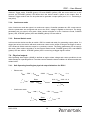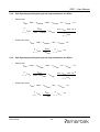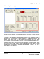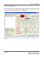
1
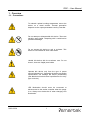
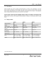
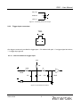
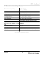
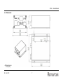
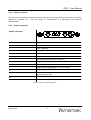
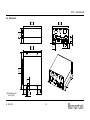
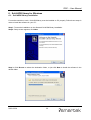
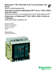
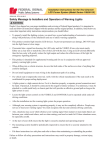
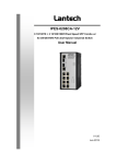
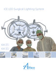
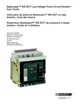
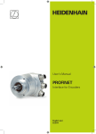
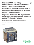
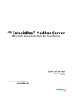
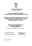
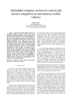
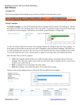
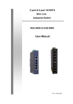
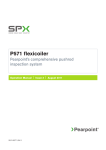
Smartek LED Strobe Controller Family User Manual Document version 1.2, last changed: 2012-02-24 IPSC1 IPSC2 IPSC4 Table of Contents 1.Overview.......................................................................................................................................1 1.1.Precautions............................................................................................................................1 1.2.Description.............................................................................................................................2 1.3.Family models........................................................................................................................2 2.IPSC1............................................................................................................................................3 2.1.Key benefits and features......................................................................................................3 2.2.Connections...........................................................................................................................3 2.2.1.Power connector............................................................................................................4 2.2.2.Output connector............................................................................................................4 2.2.3.Trigger input connectors.................................................................................................5 2.2.3.1 Internal scheme for trigger input............................................................................5 2.3.Mechanical and electrical specifications................................................................................6 2.4.Dimensions............................................................................................................................7 3.IPSC2............................................................................................................................................8 3.1.Key benefits and features......................................................................................................8 3.2.Connections...........................................................................................................................8 3.2.1.Power connector............................................................................................................9 3.2.2.Output connector............................................................................................................9 3.2.3.Trigger input connectors...............................................................................................10 3.2.3.1 Internal scheme for trigger input..........................................................................10 3.3.Mechanical and electrical specifications...............................................................................11 3.4.Dimensions..........................................................................................................................12 4.IPSC4..........................................................................................................................................13 4.1.Key benefits and features....................................................................................................13 4.2.Connections.........................................................................................................................13 4.2.1.Connecting scheme......................................................................................................13 4.2.2.Power connector..........................................................................................................14 4.2.3.Output connector..........................................................................................................14 4.2.4.Trigger input connectors...............................................................................................16 4.2.4.1 Internal scheme for trigger input..........................................................................16 4.2.5.RS-232 connector........................................................................................................17 4.3.Mechanical and electrical specifications..............................................................................18 4.4.Dimensions..........................................................................................................................19 5.Common specifications and features for all IPSC controllers......................................................20 5.1.Status LEDs.........................................................................................................................20 5.1.1.Error codes (fault codes)..............................................................................................21 5.2.Ethernet connector...............................................................................................................22 5.2.1.Ethernet status.............................................................................................................22 5.3.Software specifications........................................................................................................22 5.4.Trigger input specifications..................................................................................................23 5.4.1.Connecting optocoupled camera's digital output to IPSC's trigger input.......................23 6.ScLibSDK library for Windows.....................................................................................................24 6.1.ScLibSDK library installation................................................................................................24 6.2.Connecting strobe controller................................................................................................27 6.2.1.Connecting peer to peer with Ethernet cable................................................................27 6.2.2.Connecting ScLibClient with the strobe controller........................................................29 7.ScLibClient features....................................................................................................................32 7.1.Controller status...................................................................................................................32 7.2.Communication with controller.............................................................................................32 7.3.Running modes....................................................................................................................33 7.3.1.Off mode......................................................................................................................33 7.3.2.External Trigger mode..................................................................................................33 7.3.3.Software Trigger mode.................................................................................................33 7.3.4.Continuous mode.........................................................................................................34 7.3.5.External Switch mode...................................................................................................34 7.4.Physical outputs...................................................................................................................34 7.4.1.Safe Operating Area Region physical output limitations for IPSC1...............................34 7.4.2.Safe Operating Area Region physical output limitations for IPSC2...............................35 7.4.3.Safe Operating Area Region physical output limitations for IPSC4...............................35 7.4.4.Setting physical output parameters..............................................................................36 7.4.4.1 IPSC1 parameters...............................................................................................37 7.4.4.2 IPSC2 parameters...............................................................................................37 7.4.4.3 IPSC4 parameters...............................................................................................37 7.5.Test your illumination...........................................................................................................38 7.6.Trigger input.........................................................................................................................39 7.6.1.Setting trigger input parameters...................................................................................39 7.6.1.1 Preforming a test pulse........................................................................................40 7.7.Lightheads...........................................................................................................................41 7.8.Digital EEPROM lighthead signature (optional)....................................................................41 7.8.1.Circuits.........................................................................................................................43 7.8.2.User custom LED lighthead connection diagram..........................................................44 7.8.3.Electrical model (ideal diode, one LED)........................................................................45 7.8.3.1 U – I Characteristics.............................................................................................45 7.8.3.2 Pulse mode limitations.........................................................................................46 7.8.4.Thermal model.............................................................................................................48 7.8.5.ID Check Mode and Analog ID (optional).....................................................................49 7.9.Firmware update..................................................................................................................50 7.10.Other features....................................................................................................................52 7.10.1.Description.................................................................................................................52 7.10.2.Log.............................................................................................................................52 7.10.3.Status.........................................................................................................................52 8.Web Server.................................................................................................................................53 9.FAQ - Frequently asked questions..............................................................................................54 10.CE Conformity declaration.........................................................................................................55 11.Smartek information...................................................................................................................56 IPSC – User Manual 1. Overview 1.1. Precautions To maintain optimal working temperature mount the device on a metal surface. Thermal generation depends on the output parameters used by controller. Do not attempt to disassemble this device. There are sensitive parts inside. Tampering with it could lead to permanent damage. Do not expose this device to rain or moisture. This device is not intended to work under water. Handle this device with the maximum care. Do not throw it, there are fragile parts inside. Operate this device only from the type of power source indicated on it. Operating the device exceeding specifications can damage the device permanently (see Mechanical and electrical specifications for every type of device). LED illumination should never be connected or disconnected to the strobe controller when the power is on. Always turn the device off when changing LED illumination. 2012-02-24 1 IPSC – User Manual 1.2. Description Strobe controllers are used for strobing LED illuminations in machine vision applications. Very high power pulses are aligned to external trigger with high accuracy. Precise current overdrive and very small camera image exposition are used for acquisition of high-speed motion objects. User adjustable output voltage provides high efficiency and low power consumption. The IPSC strobe controller provides repeatable intensity control of LED lighting, it includes the power supply, intensity control, timing and triggering functions required for machine vision systems. LED lighting needs a constant current supply as small variations in voltage can cause large variations in light output. 1.3. Family models IPSC1 IPSC2 IPSC4* Output channels 1 2 4 Control Ethernet Ethernet Ethernet, RS-232 Output voltage 5V to 200V 5V to 200V 5V to 200V Max current pulse per 20A @ 200V channel 10A @ 200V 10A @ 200V Max continuous current per channel 2A @ 30V 1A @ 30V 1A @ 30V Power supply 12V – 24V DC 12V – 24V DC 12V – 24V DC Trigger inputs 1 2 4 External dimensions (H / 39 x 88 x 103 [mm] W / L) 1,54 x 3,46 x 4,06 [in] 39 x 88 x 103 [mm] 56 x 130 x 142 [mm] 1,54 x 3,46 x 4,06 [in] 2,2 x 5,13 x 5,59 [in] Weight approx. 285g (10 oz) approx. 715g (25 oz) approx. 285g (10 oz) * from HW version 2.0 2012-02-24 2 IPSC – User Manual 2. IPSC1 2.1. Key benefits and features • • • • • • • • • • • • • • • • • • • 1 Output channel Control over Ethernet interface Internal switching power supply with step-up (boost) or step-down (buck) function Adjustable output voltage from 5V to 200V Max current pulse 20A @ 200V Max continuous current 2A @ 30V Pulse width 1µs to 1000ms Online current and voltage measurements Digital EEPROM lighthead coding Temperature sensor 1 Trigger input, 5V to 24V level 12V – 24V DC power supply 12V – 24V(depends on power supply) DC output for lighthead cooling fan Analog ID (AID) and AID check mode High frame rates Very small trigger latency ~2 microseconds Input power measurement Improved 10-bit D/A converter for current control Optional 48V output voltage limitation 2.2. Connections OFF/ON switch PC Power input Ethernet cable Router Figure 1: Connecting scheme 2012-02-24 3 IPSC – User Manual 2.2.1. Power connector The input power connector is located near the lower right corner of the IPSC1’s front panel. The IPSC1 requires an external 12V – 24V DC supply for operation(see 2.3. Mechanical and electrical specifications). 2.2.2. Output connector Output connector 1 A1 6 2 7 3 8 4 5 A2 A3 9 10 Pin no. Signal 1 -Ch1, Channel 1 2 Not connected (reserved for channel 2) 3 Not connected (reserved for channel 3) 4 Not connected (reserved for channel 4) 5 Not connected (reserved for channel 5) 6 Not connected (reserved for channel 6) 7 Analog ID 8 Signal GND (GND for signals 7,9,10) 9 Trigger Output Digital Signal, 3.3V LVTTL level 10 Digital ID (1-Wire EEPROM interface, 3.3V LVTTL level) A1 12V – 24V (depends on power supply) DC, max 0.5A (for lighthead cooling fan) A2 Power GND A3 +V, Common output voltage Table 1: Output connector assignment 2012-02-24 4 IPSC – User Manual A3 (+V) Channel 1 (-Ch1) 1 Figure 2: Connecting scheme for output 2.2.3. Trigger input connectors TRG One trigger connector is provided for trigger input 1. Pin marked with plus “+” is trigger signal and minus “-” is trigger input ground. 2.2.3.1 Internal scheme for trigger input 3.3V 10K 100R 1K Ferite Bead 1nF 24V 3.3V Ferite Bead Figure 3: Input scheme for IPSC1 2012-02-24 5 100pF IPSC – User Manual 2.3. Mechanical and electrical specifications External dimensions (H / W / L) 39 x 88 x 103 [mm] 1,54 x 3,46 x 4,06 [in] Housing Black aluminum case Weight approx. 285g (10 oz) Storage temperature -30°C .. +80°C (-22°F .. +176°F) Operating temperature -5°C .. +50°C (+23°F .. +122°F) Operating relative humidity 25% .. 80% (no condensation) Power requirements 12V – 24V DC (min 11V, max 26V) Power consumption Max 3A @ 24V (72W) without cooling fan on output Max 3.5A @ 24V (84W) with cooling fan on output Output channels 1 Max current pulse (depends on pulse 20A @ 200V width) Max continuous current 2A @ 30V Pulse output range 1µs to 1000ms in 1µs increments Trigger input 0 – 5V or 0 – 24V level positive or negative edge Control Ethernet (10BaseT) Table 2: Mechanical and electrical specifications 2012-02-24 6 IPSC – User Manual 2.4. Dimensions All dimensions are in mm [inch]. 24. Feb. 2012 7 IPSC – User Manual 3. IPSC2 3.1. Key benefits and features • • • • • • • • • • • • • • • • • • • 2 Output channels Control over Ethernet interface Internal switching power supply with step-up (boost) or step-down (buck) function Adjustable output voltage from 5V to 200V Max current pulse 10A @ 200V per channel Max continuous current 1A @ 30V per channel Pulse width 1µs to 1000ms Online current and voltage measurements Digital EEPROM lighthead coding Temperature sensor 2 Trigger inputs, 5V to 24V level 12V – 24V DC power supply 12V – 24V(depends on power supply) DC output for lighthead cooling fan Analog ID (AID) and AID check mode High frame rates Very small trigger latency ~2 microseconds Input power measurement Improved 10-bit D/A converter for current control Optional 48V output voltage limitation 3.2. Connections OFF/ON switch PC Power input Ethernet cable Router Figure 4: Connecting scheme 2012-02-24 8 IPSC – User Manual 3.2.1. Power connector The input power connector is located near the lower right corner of the IPSC2’s front panel. The IPSC2 requires an external 12V – 24V DC supply for operation(see 3.3. Mechanical and electrical specifications). 3.2.2. Output connector Output connector 1 A1 6 2 7 3 8 4 5 A2 A3 9 10 Pin no. Signal 1 -Ch1, Channel 1 2 -Ch2, Channel 2 3 Not connected (reserved for channel 3) 4 Not connected (reserved for channel 4) 5 Not connected (reserved for channel 5) 6 Not connected (reserved for channel 6) 7 Analog ID 8 Signal GND (GND for signals 7,9,10) 9 Trigger Output Digital Signal, 3.3V LVTTL level 10 Digital ID (1-Wire EEPROM interface, 3.3V LVTTL level) A1 12V – 24V (depends on power supply) DC, max 0.5A (for lighthead cooling fan) A2 Power GND A3 +V, Common output voltage Table 3: Output connector assignment 2012-02-24 9 IPSC – User Manual A3 (+V) Channel 1 2 (-Ch1) 1 (-Ch2) 2 Figure 5: Connecting scheme for output 3.2.3. Trigger input connectors - TRIGGER 1 2 - One trigger connector is provided for trigger input 1 and 2. Pins marked with “1,2” are trigger signals and minus “-” are trigger input grounds. 3.2.3.1 Internal scheme for trigger input 3.3V 10K 100R 1K Ferite Bead 1nF 24V 3.3V Ferite Bead Figure 6: Input scheme for IPSC2 2012-02-24 10 100pF IPSC – User Manual 3.3. Mechanical and electrical specifications External dimensions (H / W / L) 39 x 88 x 103 [mm] 1,54 x 3,46 x 4,06 [in] Housing Black aluminum case Weight approx. 285g (10 oz) Storage temperature -30°C .. +80°C (-22°F .. +176°F) Operating temperature -5°C .. +50°C (+23°F .. +122°F) Operating relative humidity 25% .. 80% (no condensation) Power requirements 12 – 24V DC (min 11V, max 26V) Power consumption Max 3A @ 24V (72W) without cooling fan on output Max 3.5A @ 24V (84W) with cooling fan on output Output channels 2 Max current pulse (depends on pulse 10A @ 200V for each channel (20A total) width) Max continuous current 1A @ 30V for each channel (2A total) Pulse output range 1µs to 1000ms in 1µs increments Trigger input 0 – 5V or 0 – 24V level positive or negative edge Control Ethernet (10BaseT) Table 4: Mechanical and electrical specifications 2012-02-24 11 IPSC – User Manual 3.4. Dimensions All dimensions are in mm [inch]. 24. Feb. 2012 12 IPSC – User Manual 4. IPSC4 4.1. Key benefits and features • • • • • • • • • • • • • • • • • • • 4 Output channels Control over Ethernet interface Internal switching power supply with step-up (boost) or step-down (buck) function Adjustable output voltage from 5V to 200V Max current pulse 10A @ 200V per channel Max continuous current 1A @ 30V per channel Pulse width 1µs to 1000ms Online current and voltage measurements Digital EEPROM lighthead coding Temperature sensor 4 Trigger inputs, 5V to 24V level 12V – 24V DC power supply 12V – 24V(depends on power supply) DC output for lighthead cooling fan Analog ID (AID) and AID check mode High frame rates Very small trigger latency ~2 microseconds Input power measurement Improved 10-bit D/A converter for current control Optional 48V output voltage limitation 4.2. Connections 4.2.1. Connecting scheme OFF/ON switch RS-232 cable PC Ethernet cable Power input Router Figure 7: Connecting scheme 2012-02-24 13 IPSC – User Manual 4.2.2. Power connector The input power connector is located near the lower right corner of the IPSC4’s front panel. The IPSC4 requires an external 12V – 24V DC supply for operation(see 4.3. Mechanical and electrical specifications). 4.2.3. Output connector Output connector 1 A1 6 2 7 3 8 4 5 A2 A3 9 10 Pin no. Signal 1 -Ch1, Channel 1 2 -Ch2, Channel 2 3 -Ch3, Channel 3 4 -Ch4, Channel 4 5 Not connected (reserved for channel 5) 6 Not connected (reserved for channel 6) 7 Analog ID 8 Signal GND (GND for signals 7,9,10) 9 Trigger Output Digital Signal, 3.3V LVTTL level 10 Digital ID (1-Wire EEPROM interface, 3.3V LVTTL level) A1 12V – 24V DC, max 0.5A (for lighthead cooling fan) A2 Power GND A3 +V, Common Output voltage Table 5: Output connector assignment 2012-02-24 14 IPSC – User Manual A3 (+V) Channel 1 2 3 4 (-Ch1) 1 (-Ch2) 2 (-Ch3) 3 (-Ch4) 4 Figure 8: Connecting scheme for output 4.2.4. Trigger input connectors TRIGGER 1 - 1 2 3 TRIGGER 4 - Two input trigger connectors are provided. The BNC connector is for trigger input 1, and metal housing of connector is ground. The other trigger input connector is for trigger inputs 1,2,3 and 4, and pins marked with minus “-” are common trigger input grounds. Trigger input 1 (top center) and trigger input 1 (lower center) are internally connected. 4.2.4.1 Internal scheme for trigger input 3.3V 10K 100R 1K Ferite Bead 1nF 24V 3.3V Ferite Bead Figure 9: Input scheme for IPSC4 2012-02-24 15 100pF IPSC – User Manual 4.2.5. RS-232 connector The RS-232 connector is located to the upper left of the IPSC4's front panel. Connect the RS-232 cable to the RS-232 port on the IPSC4 and to a serial port on your PC. RS-232 connector 5 4 9 Pin no. Signal 2 TX 3 RX 5 GND 1,4,6,7,8,9 Not connected Table 6: RS-232 connector assignment 2012-02-24 16 2 3 8 7 1 6 IPSC – User Manual 4.3. Mechanical and electrical specifications External dimensions (H / W / L) 56 x 130 x 142 [mm] 2,2 x 5,13 x 5,59 [in] Housing Black anodized aluminum case Weight approx. 715g (25 oz) Storage temperature -30°C .. +80°C (-22°F .. +176°F) Operating temperature -5°C .. +50°C (+23°F .. +122°F) Operating relative humidity 25% .. 80% (no condensation) Power requirements 12V – 24V DC (min 11V, max 26V) Power consumption Max 5A @ 24V (120W) without cooling fan on Output Max 5.5A @ 24V (132W) with cooling fan on Output Output channels 4 Max current pulse (depends on pulse 10A @ 200V for each channel (40A total) width) Max continuous current 1A @ 30V for each channel (4A total) Pulse output range 1µs to 1000ms in 1µs increments Trigger input 0 – 5V or 0 – 24V level positive or negative edge Control Ethernet (10BaseT), RS-232 Table 7: Mechanical and electrical specifications 2012-02-24 17 IPSC – User Manual 4.4. Dimensions 4,88 124,0 0,04 1,0 0,08 2,0 2,17 55,1 4,13 105,0 0,35 9,0 5,12 130,0 4,72 120,0 All dimensions are in mm [inch]. 24. Feb. 2012 0,98 25,0 0,25 6,4 0,98 25,0 18 0,58 14,9 IPSC – User Manual 5. Common specifications and features for all IPSC controllers 5.1. Status LEDs There are 4 status LEDs on the front panel of the strobe controller. 1. POWER on IPSC4, PWR on IPSC1, P on IPSC2 2. FAULT on IPSC4, ERR on IPSC1, E on IPSC2 3. STROBE on IPSC4, STR on IPSC1, S on IPSC2 4. ARMED on IPSC4, ARM on IPSC1, A on IPSC2 When powering the device, POWER (green) and STROBE (yellow) LEDs are solid on, and the FAULT (red) LED is blinking for 5 seconds. After the startup process is done, only the POWER (green) LED stays solid on. Different LED statuses are explained in the table below: POWER (green) LED Status Solid on Controller is powered FAULT (red) LED Status Blinking in specific intervals System has a failure Blinking (in combination with STROBE (Yellow) Controller is starting up, setting controller's IP LED) address, updating firmware. The controller is in reboot mode STROBE (yellow) LED Status Blinking Indicates the pulse coming from the IPSC's output. The duration of the LED being turned on depends of the pulse length Solid on The controller is either in Continuous or External Switch mode. IPSC is driving outputs with continuous currents ARMED (yellow) LED Status Solid on Indicates voltage on output (ready for triggering pulses or in continuous mode) Table 8: LED status 2012-02-24 19 IPSC – User Manual 5.1.1. Error codes (fault codes) When controller detects errors it goes to idle mode and stops driving current on output. Depending on what type of error caused it to stop, there are 9 different error codes: • “0” - no error. • “1” - error in internal bus communication • “2” - no lighthead is detected by AID. • “3” - wrong parameters are used. • “4” - temperature of controller is to high. • “5” - error with temperature measuring device. • “6” - D/A converter failure. • “7” - input power supply voltage is to low. • “8” - can not read DID from lighthead. Depending on what error code is detected, FAULT (red) LED is blinking differently. For error code “1” it is blinking once, for error code “2” it is blinking twice, and so on. To find out which error code caused controller to stop working, we can read Fault Codes in Controller status window (see 7.1. Controller status). When errors are detected do following steps: 1. Turn off controller. 2. Disconnect lighthead. 3. Check that input power supply is connected properly. 4. Restart controller. 5. Check parameters on controller so they are not overloading controller and lighthead. 6. Check that lighthead is connected properly. 7. Send new parameters to controller. Please contact Smartek support or sales partner if error code still exist. 2012-02-24 20 IPSC – User Manual 5.2. Ethernet connector Standard protocols supported are HTTP, UDP, TCP via 10Base-T. Ethernet connector RJ45, Ethernet 10 Base-T, 803.2 compliant Pin no. Signal 1 TX+ 2 TX- 3 RX+ 6 RXTable 9: Ethernet connector assignment 5.2.1. Ethernet status Ethernet connector comes with yellow and green LED. Green LED indicates link, and yellow one indicates activity. Green LED (left one) Status Off No link Solid on Link on / Ethernet link exist Yellow LED (right one) Status Off No activity Blinking Indicates ongoing activity Table 10: Ethernet status 5.3. Software specifications Firmware update Over Ethernet ScLibSDK PC Client software Windows XP, Vista, Windows 7, 32 and 64bit Linux 32 and 64bit Table 11: Software specifications 2012-02-24 21 IPSC – User Manual 5.4. Trigger input specifications The voltage that indicates logical 0 0 to 0.5V DC Region where the transition threshold occurs, the logical state is not defined in this region +0.5V to 3V DC The voltage that indicates a logical 1 +3V to 24V DC Table 12: Input specifications 5.4.1. Connecting optocoupled camera's digital output to IPSC's trigger input To connect optocoupled digital output on camera to IPSC, just connect them like in figure below. Camera optocoupler should be able to supply min. 20mA current and be rated for min. 24V voltage. Pull down 1K2 resistor should be rated for min. 0.5W power. Camera IPSC IPSC Power supply 24V (12V) OUTPUT 1+ TRIGGER + OUTPUT 1- 1K2 (min 0.5W) TRIGGER - 2012-02-24 22 IPSC – User Manual 6. ScLibSDK library for Windows 6.1. ScLibSDK library installation For strobe controller to work, ScLibSDK library must be installed on PC properly. Follow these steps in order to install the software on your PC: Step 1: To start the installation run the Smartek ScLibSDK library installation. Step 2: Setup screen appears, click Next. Step 3: Click Browse to select the destination folder, or just click Next to install the software in the default folder. 2012-02-24 23 IPSC – User Manual Step 4: Select which components to install on the drop down menu, or click Next to continue with full installation. Step 5: Click Browse to select different folder, or click Next to install to the default Start menu folder. 2012-02-24 24 IPSC – User Manual Step 6: To install software click Install. Step 7: To complete the installation click Finish and wait for your PC to reboot. 2012-02-24 25 IPSC – User Manual 6.2. Connecting strobe controller Now that everything is installed, connect the IPSC to PC. It can be connected to PC either with serial cable (if RS-232 connector exists on IPSC) or peer to peer with Ethernet cable, or you can connect controller to network via Ethernet switch. Make sure your firewall settings are not blocking communications with controller. If that is the case, firewall must be turned off. In order to turn off the firewall in Windows, find Windows Firewall under Control Panel and turn it off. 6.2.1. Connecting peer to peer with Ethernet cable Make sure that the Local Area Connection in your Network Connections settings to which the IPSC is connected is enabled. Now PC will try to acquire network address, in case your IP address is not fixed the following message will appear. This means that an IP address should be provided manually. To provide IP address manually, right-click on the Local Area Connection to which the IPSC is connected and press Properties button. 2012-02-24 26 IPSC – User Manual Now select Internet Protocol [TCP/IP] and press Properties button. Enable Use the following IP address and type in, for example the numbers that are shown in the figure below. Note: In order for strobe controller to be connectable, the IP address that is provided manually should be on the same subnet as the strobe controller's IP address. 2012-02-24 27 IPSC – User Manual 6.2.2. Connecting ScLibClient with the strobe controller Run the ScLibClient and click Find icon to start searching for devices. To search for all devices check all boxes, or make search more specific. Depending on what type of connection is used toward strobe controller, result of search will be different. If no controller has been found check your hardware and software settings. Make sure everything is plugged properly and your firewall settings are not blocking. If you still experience problem please contact Smartek support. 2012-02-24 28 IPSC – User Manual If controller is connected with serial cable, or is connected peer to peer with Ethernet cable or via Ethernet router that has DHCP server installed and everything is OK, search results can be something like in pictures below. If controller is connected peer to peer with Ethernet cable or via Ethernet router and no DHCP server is installed, search result can look something like in picture below. IPSC are shipped in DHCP mode and in case DHCP server does not exist, IP address of device is set to invalid IP address “0.0.0.0”. Change IP address of the device to be on the same subnet as the IP address in Local Area Connection settings. To change the IP address of the IPSC click on the Set Address icon. 2012-02-24 29 IPSC – User Manual New window will open. Here you can set the new IP address, subnet mask and name of the controller. Make sure you don't provide the same IP address to controller as in Local Area Connection. If the IP address on Local Area Connection settings is the same as the IP address on the controller the following message will appear. To fix this problem change the IP address either on the controller or in Local Area Connection settings. Select the IPSC device that is found and click on the Connect icon to connect to controller. 2012-02-24 30 IPSC – User Manual 7. ScLibClient features 7.1. Controller status When connection between ScLibClient and controller is established, all fields are read out in controller status. Controller status is defined in the lower left corner of the ScLibClient software: • Controller Model – shows the model of the strobe controller. • User defined name – shows the name of the strobe controller, it can be changed by the user. • Lighthead Model – shows the model of the lighthead connected to the controller. If the lighthead does not have an digital ID, or it is not connected to the controller, the field will be empty • Unique Address – shows the mac address of the strobe controller. • Temperature [°C] – shows the internal temperature of the strobe controller. At the beginning this field is zero. Controller temperature sensor needs a few seconds to read the exact temperature. Normal internal temperature is from -5°C to +50°C (+23°F to +122°F). • Fault Code – internal error code. See 5.1.1. Error codes (fault codes) for additional information. • Input Voltage [V] – shows the controller input power supply voltage. • Max Input Power [W] – shows the maximal power of input power supply. Figure 10: IPSC status 7.2. Communication with controller The ScLibClient has read and send functions. Read button is used for reading the current parameters on the controller, and Send button is used for sending the desired parameters to the controller. After changing the desired parameters, click on the Send button to send new parameters to controller. 2012-02-24 31 IPSC – User Manual 7.3. Running modes Controller works in different modes, pulse controlled output and DC controlled output modes. Figure 11: Running modes configuration In pulse controlled output modes, controller generates electrical impulses on the output. The output pulses in this mode can be triggered by external trigger or software trigger. These modes are intended for over-driving LED lightheads. When the device reacts to one of the trigger signals, all other incoming triggers are ignored. The trigger signals are processed sequentially. These modes are External Trigger and Software Trigger mode. In DC controlled output modes controller operates as a DC current source. Those modes are intended for continuous currents on the output. These modes are Continuous and External Switch mode. 7.3.1. Off mode Controller is in idle mode and does not respond to input triggers. There is no voltage on output, output is off and controller is not waiting for trigger input. When strobe controller is in the Off mode only POWER (green) LED is solid on. 7.3.2. External Trigger mode In this mode, device is ready to accept external trigger input and generate an output pulse. External Trigger mode is the most precise mode of the IPSC. This is because there is very low (min. ~2 microseconds) latency between the arriving trigger input and the output pulse coming form IPSC. When strobe controller is in the External Trigger mode, POWER (green) LED and ARMED (yellow) LED are turned solid on. In this process, the STROBE (yellow) LED blinks when the device sends a pulse on the output. 7.3.3. Software Trigger mode In this mode the device is ready to accept software trigger input and generate an output pulse. Controller does not respond to external trigger inputs but does to the software trigger via RS-232 cable or Ethernet cable. Software Trigger mode is not precise as the External Trigger or External Switch mode. This is because of the delay between the device and the PC. When strobe controller is in the 2012-02-24 32 IPSC – User Manual Software Trigger mode, POWER (green) LED and ARMED (yellow) LED are turned solid on. In this process, the STROBE (yellow) LED blinks when the device sends a pulse on the output. Also, in Software Trigger mode a test can be preformed to generate a output pulse (see 7.6.1.1. Preforming a test pulse). 7.3.4. Continuous mode In the Continuous mode the output is a continuous current. Controller operates as a DC current source. After the parameters are configured and sent to the IPSC, voltage is applied to the output. The timing parameters are not used in this mode. When strobe controller is in the Continuous mode, POWER (green) LED, STROBE (yellow) LED and ARMED (yellow) LED are solid on. 7.3.5. External Switch mode In this mode the device acts like an switch. IPSC is armed and ready for generating output pulses. If a trigger has arrived, the device will send continuous current on the output as long as the trigger is active. In the External Switch mode the output is a continuous current. The timing parameters are not used in this mode. When strobe controller is in the External Switch mode, POWER (green) LED, and ARMED (yellow) LED are solid on. STROBE (yellow) LED is on as long as trigger signal is active. 7.4. Physical outputs Safe Operating Area Region (SOAR) is defined as region where voltage and current conditions do not make damage on operating device. Formulas used to determine those conditions in different modes are written below: 7.4.1. Safe Operating Area Region physical output limitations for IPSC1 • Pulse mode: P = 70W max ; U out max P 1 max ∑ i out ≤ ∂ × U n n= 1 max out • ; = 200V ; max t U out on max min = 5V ; t on min × 200 × 10 − 6 out 1 ∑ i out n n= 1 0.12 × U ≤ Continuous mode: P = 70W max ; U out max P 1 max ∑ i out ≤ U n n= 1 out max 2012-02-24 = 55V ; 33 = 1µ s ; U out min = 5V 1 ∑ i out ≤ 2 A n n= 1 IPSC – User Manual 7.4.2. Safe Operating Area Region physical output limitations for IPSC2 • Pulse mode: P = 70W max ; U out P 2 max ∑ i out ≤ ∂ × U n n= 1 max out • ; = 200V max ; t max U out on max = 5V min ; t on min = 1µ s × 200 × 10 − 6 out 2 ∑ i out n n= 1 0.12 × U ≤ Continuous mode: ; P = 70W max U out max ; = 55V P 2 max ∑ i out ≤ U n n= 1 out max ; U out min = 5V 2 ∑ i out ≤ 2 A n n= 1 7.4.3. Safe Operating Area Region physical output limitations for IPSC4 • Pulse mode: P = 110W max ; U out max P 4 max ∑ i out ≤ ∂ × U n n= 1 max out • = 200V ; max t ; U out on max min ≤ = 5V ; t on min × 330 × 10 − 6 out 4 ∑ i out n n= 1 0.12 × U Continuous mode: P = 110W max ; U out max P 4 max ∑ i out ≤ U n n= 1 out max 2012-02-24 = 55V ; 34 = 1µ s ; U out min = 5V 4 ∑ i out ≤ 4 A n n= 1 IPSC – User Manual 7.4.4. Setting physical output parameters Figure 12: Physical output configuration By setting the output parameters, current and voltage power can be configured. Be careful with output parameters because bad settings can damage the LED illumination. For example: If Max Voltage is set to 50V and Optimal Autosense is enabled, voltage that is applied on the output is 50V, but needed voltage for optimal performance is 28V (Measured Voltage [V]). Now when the optimal voltage is known, it is faster to set the desired parameters and not use Optimal Autosense option. This feature is provided by the voltage and current gauges located inside the IPSC. Optimal Autosense is used to determine optimal output voltage for the current settings. When Optimal Autosense check box is enabled, the device corrects the desired voltage to lower voltage so that the dissipation on the output MOSFETs is reduced and maximal dissipation for IPSC1 is 10W, and for IPSC2 and IPSC4 is 5W per channel. 2012-02-24 35 IPSC – User Manual 7.4.4.1 IPSC1 parameters Current – current can be set between 0 – 20A for pulse controlled mode and between 0 – 2A for DC controlled mode. • Max Voltage – voltage can be set between 5 – 200V for pulse controlled modes and between 5 – 55V for DC controlled modes. • Trigger – select which trigger will be used for external triggering of output channel. IPSC1 has improved 10-bit D/A converter, which gives more scaling accuracy while controlling current. Scale up to 500mA has step accuracy 1mA, and from 500mA and above step accuracy is 20mA. 7.4.4.2 IPSC2 parameters Current – current can be set between 0 – 10A on each channel for pulse controlled modes and between 0 – 1A on each channel for DC controlled modes. • Max Voltage – voltage can be set between 5 – 200V on each channel for pulse controlled modes and between 5 – 55V on each channel for DC controlled modes. • Trigger – select which trigger will be used for external triggering of output channels. IPSC2 has improved 10-bit D/A converter, which gives more scaling accuracy while controlling current. Scale up to 250mA has step accuracy 1mA, and from 250mA and above step accuracy is 10mA. 7.4.4.3 IPSC4 parameters Current – current can be set between 0 – 10A on each channel for pulse controlled modes and between 0 – 1A on each channel for DC controlled modes. • Max Voltage – voltage can be set between 5 – 200V on each channel for pulse controlled modes and between 5 – 55V on each channel for DC controlled modes. • Trigger – select which trigger will be used for external triggering of output channels. IPSC4 has improved 10-bit D/A converter, which gives more scaling accuracy while controlling current. 2012-02-24 36 IPSC – User Manual 7.5. Test your illumination Provide the desired current(1) and voltage(2) settings. Make sure that settings don't exceed the limits of strobe controller and connected illumination, use Optimal Autosense to determine optimal output voltage. Set Running mode to Continuous and click on Send button. The strobe controller now continuously drives current to the lighthead. The lighthead should now illuminate. 2012-02-24 37 IPSC – User Manual 7.6. Trigger input 7.6.1. Setting trigger input parameters Figure 13: Setting trigger input parameters Trigger Inputs parameters are not used if controller is in Continuous, External Switch or Off mode. With these parameters, timing and triggering options of LED illuminations are configured. Parameters have resolution of 1µs: • Trigger Edge – configuration of controller's input trigger edge. If the trigger edge is not the same between camera and strobe controller, asynchronization may occur between them. • Delay Time – time interval between the receipt of a trigger signal and the initiation of an output pulse. Minimal delay time is 2µs and cannot be shorter because there is a minimal response time of the hardware which is a fixed value (hardware latency). Input trigger response jitter is ±0.1µs. • On Time – definition of the impulse length of the input. This is the most important parameter, lighthead illuminates over this time. Please be careful with On Time parameter. Too high value of On Time can damage the lightheads. • Off Time – the time when no trigger is accepted, internal strobing capacitors are recharged. • Trigger 1, 2, 3, 4 – enable or disable trigger. Rising edge External trigger signal Output pulse New triggers are ignored Delay Time On Time New valid triggers Off Time Output pulse Falling edge External trigger signal Output pulse New triggers are ignored Delay Time On Time Off Time Output pulse Figure 14: Process of generating pulses 2012-02-24 38 New valid triggers IPSC – User Manual 7.6.1.1 Preforming a test pulse Figure 15: Test pulse configuration To preform a test pulse, the device has to be in Software Trigger(1). Select a Single Pulse or a Repeated 10Hz(2) option. After the parameters are set and sent to IPSC, click on Fire(3) button to preform the test. Notice how the Event Counter(4) field is counting the number of pulses that IPSC sends. Make sure that parameters in Physical Output and Trigger Input fields doesn't overload strobe controller and connected illumination, to be on the safe side make sure that Optimal Autosense check box is enabled. Repeated 10Hz pulse is the same as the Single Pulse, except that the device repeatable sends impulses to the lighthead. IPSC1, IPSC2 and IPSC4 comes with improved current controlling. Measured Current[mA](5) gives measure value depending of Current value and On Time value. For impulses shorter then 10µs measuring is not valid, to change length of impulse change value of On Timer(6), please be careful with On Time parameter. Too high value of On Time can damage the illumination. 2012-02-24 39 IPSC – User Manual 7.7. Lightheads To access the lightheads options click on the Lightheads tab. By using the Auto Detect button additional information is provided about the currently connected lightheads. Only the lightheads with digital lighthead signature can provide additional information. Digital lighthead signature is an optional feature. If digital lighthead signature exists, Vendor, Model, Serial Number and Unique ID are read out. While connecting custom illumination, be careful with limitations of LEDs. Bad settings can damage the illumination permanently. 7.8. Digital EEPROM lighthead signature (optional) Digital EEPROM lighthead signature or Digital ID(DID) is a feature which is used for protecting the lightheads from damaging and provides additional information about the lightheads. Currents driven through LEDs exceeding the specifications can damage LEDs. Digital lighthead signature is stored on the EEPROM of the lighthead and is accessed trough IPSC controller over 1-Wire protocol. IPSC Lighthead Signal GND Output connector GND 1 Data 2 NC 3 8 Digital ID Lighthead cable 10 DS2433, 4Kb 1-wire EEPROM EEPROM that is supported by the IPSC is Dallas, Maxim DS2433 4Kb 1-Wire EEPROM. The lighthead can be with or without digital lighthead signature/EEPROM. 2012-02-24 40 IPSC – User Manual Digital lighthead signature of the lighting device is accessed by pressing the F4 key on keyboard. In the Digital Lighthead Signature window, additional information is provided about strobe controller and lighthead. Figure 16: Additional information about strobe controller and lighthead Controller – these parameters are changed when changing IP address of the strobe controller. These parameters are also read out in the controller status field: • Connection – IP address of the strobe controller. • Model – model of the strobe controller. • User Name – name that's given when changing IP address of the strobe controller or a default name. • Unique ID – unique ID of the lighthead. Unique ID – unique ID of the lighthead. Lighthead Signature Data – these parameters are changed when writing new digital signature. These parameters are also read out in the Lightheads tab: • Vendor – vendor of the lighthead. • Model – model of the lighthead. • Serial Number – serial number of the lighthead. 2012-02-24 41 IPSC – User Manual 7.8.1. Circuits A new circuit is added by selecting the Append New Circuit(1) button. Parameters for circuits are defined under Circuit tab. To save current parameters click Save File(2) button. To update signature in EEPROM with current parameters click on Write EEPROM(3) button. To see current parameters in raw hex format go to Raw EEPROM Signature Data(4) tab. Single Circuit Definition defines parameter for single circuit: • Circuit Description – defines the name of circuit. • User Data – circuit user data. • LED Serial Count – number of LEDs connected in series. • LED Parallel Count – number of LEDs connected in parallel. • Joined Channels Count – number of connected channels in custom illumination. 2012-02-24 42 IPSC – User Manual Single LED Data Definition section defines parameters for the single LED: • LED Type ID – user configurable, with a value between 0 – 66535. • LED Wavelength – wavelength of the LED determines the color of the LED, with a value between 0 – 255[x10nm]. • Forward Voltage (Uf) – maximum forwarded voltage on a LED, with a value between 0.00 – 600.00[V]. This value should be read out from the specifications of the LED. • Dynamic Resistance (Rf) – LEDs electrical resistance when it is in operation, with a value between 0.00 – 600.00[Ohm]. This value should be read out from the specifications of the LED. • Max DC Current (Built in lighthead) – maximal allowable current trough LED when built in lighthead with a value between 1 – 65535[mA]. • Max Pulsed Current – maximal allowable current trough LED when the device is in pulse mode, with a value between 1 – 65535[mA] (see 7.8.3.2. Pulse mode limitations). • Max DC Power (LED only) – maximal DC power which can run through single LED, with a value between 0 – 65535[mW]. This value should be read out from the specifications of the LED. • RC Thermal – time constant obtained by multiplication of thermal capacity and thermal resistance, with a value between 0 – 655350[us]. This value is obtained from the LED datasheet. • Max On Time – maximum value for On Time when in the pulse controlled mode, with a value between 0 – 655350[us] (see 7.8.3.2. Pulse mode limitations). 7.8.2. User custom LED lighthead connection diagram (+V) Strip of LEDs connected in series (-Chx) Strip of LEDs connected in parallel Figure 17: Parallel & serial LED connections The figure below is an example how the LEDs can be connected on one channel. 2012-02-24 43 IPSC – User Manual 7.8.3. Electrical model (ideal diode, one LED) Electrical modeling of diodes refers to the mathematical models used to approximate the actual behavior of real diodes to enable calculations and circuit analysis. In calculation the real diode behavior can be approximated with mathematical model. Forward current (A) Math approximation Real Figure 19: Real diode model Forward voltage (V) Figure 18: Real diode model approximation 7.8.3.1 U – I Characteristics • Calculating voltage: U [V ] = U + R ⋅ I f f • Calculating current: I [ A] = • −U + f U 2 + 4⋅ R ⋅ P f f 2⋅ R f Calculating power: P [W ] = U ⋅ I + R ⋅ I 2 f f Forward voltage U [V ] and dynamic resistance R [Ω ] are constants. f f 2012-02-24 44 IPSC – User Manual 7.8.3.2 Pulse mode limitations In the figure below is shown the Safe Operating Area of an diode. The maximum input power curve can be calculated with the formula below: Current Maximum pulsed current limit Maximum input power limit Safe Operating Area Pulse duration Maximum On Time limit Figure 20: Safe Operating Area of an diode • Calculating maximum value for power: t + t − on off RC th 1− e P [W ] = P ⋅ pul _ max dc _ max t − on RC th 1− e • Calculating maximum value for On Time: P pul _ max 1 − P dc _ max t [s ] = − ln on t off − P RC th − pul _ max e P dc _ max 2012-02-24 45 ⋅ RC th IPSC – User Manual • Calculating minimum value for Off Time: P 1 − pul _ max P dc _ max P pul _ max t [s ] = − ln + off t P dc _ max − on RC th e ⋅ RCth To make calculation on diode with it's parameters use following example: • Thermal resistance Rth = 700 • Thermal capacity Cth = 52 • Diode forward voltage Uf [V ] = 1,9V • Dynamic resistance Rf [Ω ] = 4Ω • Maximal DC power Pdc _ max [W ] = 78,6mW • Time constant RCth [s ] = 36,4ms P [W ] pul _ max 233,7990 116,9227 58,4846 29,2655 23,4217 11,7341 4,1475 3,9424 2,3841 1,2155 0,6314 0,3398 0,2817 0,1663 0,1107 0,0830 0,0786 2012-02-24 I [ A] U [V ] 7,411 5,174 3,594 2,478 2,194 1,492 0,808 0,783 0,570 0,363 0,225 0,138 0,119 0,076 0,052 0,040 0,038 31,55 22,6 16,27 11,81 10,68 7,87 5,13 5,03 4,18 3,35 2,8 2,45 2,37 2,2 2,11 2,06 2,05 max 46 t on [s ] 1,00E-005 2,00E-005 4,00E-005 8,00E-005 1,00E-004 2,00E-004 5,70E-004 6,00E-004 1,00E-003 2,00E-003 4,00E-003 8,00E-003 1,00E-002 2,00E-002 4,00E-002 1,00E-001 1,00E+000 t off [s ] 6,19E-002 6,19E-002 6,19E-002 6,19E-002 6,19E-002 6,19E-002 6,19E-002 6,19E-002 6,19E-002 6,19E-002 6,19E-002 6,19E-002 6,19E-002 6,19E-002 6,19E-002 6,19E-002 6,19E-002 IPSC – User Manual 7.8.4. Thermal model Diagram of thermal mode shows the temperature increase of LED silicon die. When LED diode is on, it has a tendency to develop heat. On Time represents the time the current is passing trough the LED. Temperature of the LED silicon die should never pass the Qmax . Also, there is some minimum time interval t off required to allow LED to cool down. This is shown in the diagram below. Q(°C) Q (°C) Q (°C) max min On Time (t on ) Off Time (t ) off t(s) Figure 21: Temperature increase of LED In order to maintain a low temperature to keep good performance of an LED, releasing heat from LEDs should be considered. In the figure below is a typical thermal model of an LED. R th C th Figure 22: Thermal model of an LED • R = thermal resistance th • C = thermal capacity th 2012-02-24 47 IPSC – User Manual 7.8.5. ID Check Mode and Analog ID (optional) IPSC1, IPSC2 and IPSC4 with firmware version 1.2 and up provide optional features. ID Check Mode is used to preform checking of Digital ID and Analog ID. To change setting for ID Check Mode, please contact our sales partner or Smartek support. ID Check Mode – gives information for ID Check Mode setting: • 0 – IPSC does not perform any checking • 1 – IPSC checks for AID at startup • 2 and 3 – IPSC checks for AID continuously all the time • 4 – IPSC checks for DID at startup • 5 – IPSC checks for DID and AID at startup • 6 and 7 – IPSC checks for DID at startup and AID continuously all the time Analog ID is optional feature to check if lighthead is connected to IPSC. Pins 7 and 8 on IPSC output are connected with 1K resistor. IPSC Lighthead Analog ID 7 Output connector Lighthead cable Signal GND 8 Analog ID – reads status of AID for lighthead: • 128 ± 8 – Lighthead is not connected • 97 ± 8 – Lighthead is connected • 68 ± 8 – AID output is connected to GND 2012-02-24 48 1K IPSC – User Manual 7.9. Firmware update Firmware update is done via Ethernet, in order to update the firmware, the IP address of controller has to be permanent not in DHCP mode (see 6.2.2 Connecting ScLibClient with the strobe controller how to set permanent IP address on controller), and controller needs to be in Off mode (see 7.3.1. Off mode).To update the firmware follow these steps: Go to Status tab and press Firmware Update button. Click on the Browse button to select a firmware to install. Find and open a firmware to install. After opening a firmware, click on the Check firmware file button to run a compatibility test between the device and firmware. 2012-02-24 49 IPSC – User Manual If the selected firmware is compatible, “PASSED” is indicated in text window and Upload new firmware to device button will become available. Click on Upload new firmware to device button to start updating the firmware. During this process, POWER (green) LED and STROBE (yellow) LED are solid on, while the FAULT (red) LED is blinking. After programming is done, “PASSED” is indicated in text window. This process can take a couple of minutes. When updating of new firmware finishes, simply close the dialog box. 2012-02-24 50 IPSC – User Manual 7.10. Other features 7.10.1. Description Go to Description tab to see major features, specifications and maximum ratings of controller that is connected to ScLibClient. 7.10.2. Log To see actual logging information go to Log tab. To save actual log, just click Save to File button and save it on disk. 7.10.3. Status To see actual status information about controller go to Status tab. 2012-02-24 51 IPSC – User Manual 8. Web Server IPSC strobe controllers are accessible through web interface. To gain access just enter IP address(1) of IPSC in web browser. Use Web Server to read and send parameters to device(2), or use it to change IP address of controller(3). 2012-02-24 52 IPSC – User Manual 9. FAQ - Frequently asked questions 2012-02-24 53 IPSC – User Manual 10. CE Conformity declaration We, Smartek d.o.o. Ziskovec 141, HR-40000 Cakovec, Croatia Contact Person: Mr. Damir Dolar Email: [email protected] Hereby declare that: Product: Internet Protocol Strobe controller Type Family: Smartek Strobe Controller Type: IPSC1, IPSC2, IPSC4 Is in compliance with the essential requirements and other relevant provisions of the following EC directives. Reference No. Title 89/336/EEC, 92/31/EEC Electromagnetic Compatibility (EMC directive) Following standards or normative documents: EN 55022:1994 Class A + A1:1995 + A2:1997, EN 61326:1997 Class A + A1:1998 + A2:2001 + A3:2003, EN 55024:1998 + A1:2001 + A2:2003 The product specified above was tested conforming to the applicable Rules under the most accurate measurement standards possible, and that all the necessary steps have been taken and are in force to assure that production units of the same product will continue comply with the requirements. 2012-02-24 Damir Dolar Dipl. Ing. Hardware Engineer Smartek d.o.o. 2012-02-24 54 IPSC – User Manual 11. Smartek information Published by: Smartek d.o.o. Ziskovec 141, HR-40000 Cakovec Croatia www.smartek.hr Email: [email protected] Tel: ++385 40 86 57 32 Fax : ++385 40 86 57 31 Copyright © 2012 by Smartek d.o.o. All rights reserved. For further information please contact our sales partners. 2012-02-24 55