1
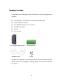
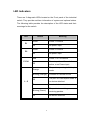
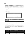
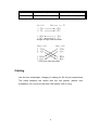
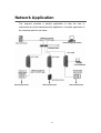
5 port & 8 port 10/100TX Slim Line Industrial Switch HUE-500S & HUE-800S User Manual Rev.1.2 08/13/2007 FCC Warning This Equipment has been tested and found to comply with the limits for a Class A digital device, pursuant to Part 15 of the FCC rules. These limits are designed to provide reasonable protection against harmful interference in a residential installation. This equipment generates, uses and can radiate radio frequency energy and, if not installed and used in accordance with the instructions, may cause harmful interference to radio communications. However, there is no guarantee that interference will not occur in a particular installation. If this equipment does cause harmful interference to radio or television reception, which can be determined by turning the equipment off and on, the user is encouraged to try to correct the interference by one or more of the following measures: Reorient or relocate the receiving antenna. Increase the separation between the equipment and receiver. Connect the equipment into an outlet on a circuit different from that to which the receiver is connected. Consult the dealer or an experienced radio/TV technician for help. CE Mark Warning This is a class A product. In a domestic environment this product may cause radio interference in which case the user may be required to take adequate measures. Contents FCC Warning ........................................................... 1 CE Mark Warning..................................................... 1 Introduction......................................................... 1 Features ................................................................... 1 Package Contents.................................................... 2 Hardware Description ......................................... 3 Physical Dimensions ................................................ 3 Front Panel............................................................... 3 Top View .................................................................. 4 Wiring the Power Inputs ........................................... 4 LED Indicators.......................................................... 7 Ports......................................................................... 8 Cabling ..................................................................... 9 Mounting Installation ........................................ 10 DIN-Rail Mounting.................................................. 10 Wall Mount Plate Mounting .................................... 12 Hardware Installation........................................ 13 Installation Steps.................................................... 13 Network Applications ........................................ 14 Troubleshooting................................................ 15 Technical Specifications................................... 16 Introduction The HUE-500S and HUE-800S Industrial Switches are a cost-effective solution and meet the high reliability requirements demanded by industrial applications. They provide the redundant power inputs that prevent power failure. Features 5 (HUE-500S) & 8 (HUE-800S) port 10/100TX industrial switches Store-and-Forward switching architecture Conforms to IEEE 802.3 10Base-T, 802.3u 100Base-TX RJ-45 ports support automatic MDI/MDI-X function 1G bps Back-plane 2K MAC address table IEEE 802.3x flow control support ¾ Flow control on full-duplex ¾ Back pressure on half-duplex Wide-range redundant power design Reverse Polarity Power Protection Overload Current Re-settable Fuse DIN rail and wall mount design Meets IP-30 case protection Provides 3000 VDC EFT power line protection Supports 4000 VDC Ethernet ESD protection Supports 10-48VDC or 18~30VAC Power inputs Alarm Relay for Power failure (NO contact) 1 Package Contents Please refer to the package content list below to verify them against the checklist. 5 (HUE-500S) / 8 (HUE-800) 10/100TX Industrial Switch Terminal Block connector One DIN-Rail (attached on the switch) 2 Wall-Mount plates Screws User manual 5-port 10/100TX industrial switch Wall Mount racks Block Connector Screws Compare the contents of your industrial switch with the standard checklist above. If any item is damaged or missing, please contact your local dealer for service. 2 Hardware Description In this paragraph, we will introduce the Industrial switch’s hardware spec, port, cabling information, and wiring installation. Physical Dimensions HUE-500S Industrial Switch dimensions (W x D x H) are 25mm x 95mm x 130mm Front Panel The Front Panel of the HUE-500S Industrial Switch is showed as the following figure. LED Indicator UTP Port Front Panel of the HUE-500S Industrial Switch 3 Top View The top panel of the HUE-500S Industrial Switch has one terminal block connector for two DC power inputs. Top Panel of the 5 10/100TX Industrial Switch Wiring the Power Inputs Please follow below steps to insert the power wire. V- V+ V- V+ 1. Insert the positive and negative wires into the V+ and Vcontacts in the terminal block connector. [NOTE] The wire range of the terminal block is from 12~24AWG. 2. Tighten the wire-clamp screws. 4 Notice: The HUE-500S / 800S supports both AC and DC power inputs. Never connect AC and DC power on the same terminal block - even for testing. 5 Wiring the Fault Alarm Contact The fault alarm contact is in the middle of terminal block connector as the figure shows. By installing the wires, it will detect a power failure, and close the open circuit. An application example for the fault alarm contact is below: The contact closure ( NO ) is fail safe – power on – held closed. 1A@24V Insert the wires into the fault alarm contact [NOTE] The wire gauge of the terminal block is from 12~ 24 AWG. 6 LED Indicators There are 3 diagnostic LEDs located on the Front panel of the industrial switch. They provide real-time information of system and optional status. The following table provides the description of the LED status and their meanings for the switch. LED Status Meaning Green Power 1 is active Off No power input Green Power 2 is active Off No power input Red Power 1 or 2 is inactive P1 P2 P-Fail Power input 1 and 2 are both Off active, or no Power input The port is operating in full-duplex Orange mode Blinking (Orange) Collision of Packets occurs The port is in half-duplex mode or Off no device attached 1~5 Green A network device is detected The port is transmitting or Blinking (Green) receiving packets Off No device attached 7 Ports RJ-45 ports (Auto MDI/MDIX): 5/8 x 10/100Mbps auto-sensing ports for the 10Base-T or 100Base-TX device connections. The UTP ports will auto-sense for 10Base-T or 100Base-TX connections. Auto MDI/MDIX means that you can connect to another switch or workstation without changing straight through or crossover cables. See Figure C and C-1 for straight through and crossover cable schematic. RJ-45 Pin Assignments Pin Number Assignment 1 Tx+ 2 Tx- 3 Rx+ 6 RxTable 1 [NOTE] “+” and “-” signs represent the polarity of the wires that make up each wire pair. All ports on this industrial switch support automatic MDI/MDI-X operation, you can use straight-through cables (See Figure below) for all network connections to PCs or servers, or to other switches or hubs. In straight-through cable, pins 1, 2, 3, and 6, at one end of the cable, are connected straight through to pins 1, 2, 3 and 6 at the other end of the cable. The table below shows the 10BASE-T/ 100BASE-TX MDI and MDI-X port pin outs. Pin MDI-X Signal Name MDI Signal Name 1 Receive Data plus (RD+) Transmit Data plus (TD+) 2 Receive Data minus (RD-) Transmit Data minus (TD-) 8 3 Transmit Data plus (TD+) Receive Data plus (RD+) 6 Transmit Data minus (TD-) Receive Data minus (RD-) Table 2 Straight Through Cable Schematic Cross Over Cable Schematic Cabling Use the four twisted-pair, Category 5 cabling for RJ-45 port connections. The cable between the switch and the link partner (switch, hub, workstation, etc.) must be less than 100 meters (328 ft.) long. 9 Mounting Installation DIN-Rail Mounting The DIN-Rail is installed on the industrial switch from the factory. If the DIN-Rail is not installed on the industrial switch, please see the following pictures to mount the DIN-Rail on the switch. Follow the steps below to mount the industrial switch. Rear Panel of the switch DIN-Rail 1. Use the screws to mount the DIN-Rail on the industrial switch 2. To remove the DIN-Rail, reverse the step 1. 3 10 1. First, insert the top of DIN-Rail into the track. 2. Then, lightly push the button of DIN-Rail into the track. 3. Check that the DIN-Rail is tightly on the track. 4. To remove the industrial switch from the track, reverse the steps above. 11 Wall Mount Plate Mounting Follow the steps below to mount the industrial switch with the wall mount plate. 1. Remove the DIN-Rail from the industrial switch; remove the screws to remove the DIN-Rail. 2. Place the wall mount plate on the rear panel of the industrial switch. 3. Use the screws to mount the wall mount plate on the industrial switch. 4. Use the hook holes at the corners of the wall mount plate to mount the industrial switch on the wall. 5. To remove the wall mount plate, reverse the steps above. Mounting the wall mount plate on the Industrial switch 12 Hardware Installation In this paragraph, we will describe how to install the HUE-500S / HUE-800S Industrial Switch. Installation Steps 1. Unpack the Industrial switch 2. Check if the DIN-Rail is screwed on the Industrial switch. If the DIN-Rail is not screwed on the Industrial switch, please refer to the DIN-Rail Mounting section for DIN-Rail installation. 3. To mount the Industrial switch on the DIN-Rail track on the wall, please refer to the Mounting Installation chapter. 4. Power up the Industrial switch. Please refer to the Wiring the Power Inputs section for the information about how to wire the power. The power LED on the Industrial switch will light up. Please refer to the LED Indicators section for indication of LED lights. 5. Prepare the twisted-pair, straight through Category 5 cable for an Ethernet connection. 6. Insert one end of RJ-45 cable (category 5) into the Industrial switch Ethernet port (RJ-45 port) and the other end of RJ-45 cable (category 5) to the network device’s Ethernet port (RJ-45 port), e.g. the Switch PC or Server. The UTP port (RJ-45) LED on the Industrial switch will light up when the cable is connected with the network device. Please refer to the LED Indicators section for LED light indication. [NOTE] Make sure that the connected network devices support MDI/MDI-X. If it does not, then use a crossover category-5 cable. 7. When all connections are done and the LED lights all show normal, the installation is complete. 13 Network Application This segment provides a sample application to help the user to understand an actual industrial switch application. A sample application of the industrial switch is as below. 14 Troubleshooting Verify that you are using the right power supply (DC 10-48V), DO NOT use a power adapter with a DC output higher than 48V, or it will destroy the switch’s power section. Select the proper UTP cable to construct the user network. Please check that you are using the right cable. Use unshielded twisted-pair (UTP) or shield twisted-pair ( STP ) cable for RJ-45 connections: 100 Ω Category 3, 4 or 5 cable for 10Mbps connections or 100 Ω Category 5 cable for 100Mbps connections. Also, be sure that the length of any twisted-pair connection does not exceed 100 meters (328 feet). Diagnostic LED Indicators: The Switch can be easily monitored through the panel indicators, which describe common problems the user may encounter and where the user can find possible solutions to assist in identifying problems. If the power indicator does not light up when the power terminal strip is plugged in, the user may have a problem with power supply. Check for loose power connections; power losses or surges at power supply. If the user still cannot resolve the problem, contact the local Ethernet Direct dealer for assistance. If the Industrial switch LED indicators are normal and the connected cables are correct, but the packets still cannot transmit, check your system’s Ethernet devices’ configuration or status. 15 Technical Specifications The HUE-500S / HUE-800S Industrial Switch technical specifications are as follows. Standard IEEE 802.3 10Base-T Ethernet IEEE 802.3u 100Base-TX Fast Ethernet Protocol CSMA/CD Technology Store and Forward Transfer Rate MAC address 14,880 pps for Ethernet port 148,800 pps for Fast Ethernet port 2K MAC address table Per port: Link/Activity (Green) LED Full duplex/Collision (Orange) Per unit: P-Fail (Red), Power 1 (Green), Power 2 (Green) 10Base-T: 2-pair UTP/STP Cat. 3, 4, 5 cable Network Cable EIA/TIA-568 100-ohm (100m) 100Base-TX: 2-pair UTP/STP Cat. 5 cable EIA/TIA-568 100-ohm (100m) Back-plane 1.0G bps 10~48 VDC / 18~30 VAC, Redundant power Power Supply with reverse polarity protection and removable terminal block 16 Power consumption Packet throughput ability Installation Operating 2.6 Watts (12VDC), 1.3 Watts (24VDC) 1.49Mpps @64bytes (5TX) DIN rail kit and wall mount kit -10℃ to 70℃ Temperature Operating Humidity Storage Temperature Ambient Relative Humidity Dimensions 5% to 95% (Non-condensing) -40 to 85°C 5% to 90%(non-condensing) IP-30, 25 mm (W) x 95 mm (D) x 130mm (H) FCC Class A, CE EN61000-4-2 (ESD), CE EN61000-4-3 (RS), CE EN-61000-4-4 EMI (EFT), CE EN61000-4-5 (Surge), CE EN61000-4-6 (CS), CE EN61000-4-8, CE EN61000-4-11, CE EN61000-6-2, CE EN61000-6-4 Stability testing IEC60068-2-32 (Free fall), IEC60068-2-27 (Shock), IEC60068-2-6 (Vibration) 17