1
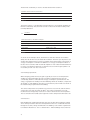
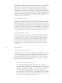
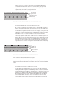
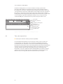
Instructions Before installation April 2014 A Dinesen floor is a unique piece of nature. It is a living material which must be treated with care. Our instructions explain in detail how you get the best result so the floor can last for centuries. If you need any additional advice about Dinesen floors, you are very welcome to contact us. To order and purchase products in the maintenance series, please go to webshop.dinesen.com Contents 1 A solid plank floor7 1.1 The properties of wood 2 How to succeed8 7 2.1 General requirements for humidity and climate 8 3 Humidity 9 3.1 Humidity and plank floors 3.2 Air humidity 3.3 Construction humidity 3.4 Drying of concrete 3.5 Humidity in the substructure 3.6Damage 3.7 Measuring residual humidity 3.8 Liability and warranty 3.9 Change of delivery time 9 9 9 10 10 10 10 11 11 4 12 Underfloor heating under Dinesen floors 4.1Conditions 4.2 Types of underfloor heating 4.3Constructions 4.4 Test, start-up and use 12 14 15 19 5Pitfalls20 5.1 Dinesen recommends 20 6FAQ 21 7 General guidance23 7.1 Dinesen instructions 7.2Literature 23 23 1 A solid plank floor A solid plank floor from Dinesen provides a firm foundation. To ensure the high level of quality and careful processing, every plank passes through 10 pairs of hands on its way through the production process. Generally, we always recommend the thicker planks. They are more stable, have a deeper sound and last a generation or two longer. Dinesen planks are always delivered unfinished, and after installation, the floor must be sanded and finished. This gives you the opportunity to choose the finish that matches your expectations of the floor. It is important to consider the advantages and disadvantages of the various finishes carefully. You can read more about this in Dinesen’s “After installation” instructions. 1.1 The properties of wood Wood is a hygroscopic material, which absorbs and emits moisture from the surrounding materials. Wood will always adapt to an equilibrium level of humidity in relation to the temperature and the relative humidity of the air. When delivered, Dinesen planks are dried to a moisture content of 8-10%. This corresponds to a relative air humidity (RH) of 40-50%. If the air humidity decreases, the wood will emit moisture and shrink in width, which results in contraction gaps. Contraction gaps will always appear in winter, and at this stage, the floor has its most beautiful appearance. Generally, however, the goal should be to prevent the air humidity from dropping below 35% RH. Below is an overview of the reaction of the floor planks to varying degrees of air humidity at a normal temperature of 18-25 °C. The recommended intervals and tolerances in air humidity are highlighted in grey. The overview applies to a correctly installed floor, cf. the guidelines in this and the other instructions from Dinesen, and the information is only intended as a general guide. Climate condition Reaction 60-70 % RF Slight transverse warping should be expected 50-60 % RF No contraction gaps, slight warping should be expected 40-50 % RF The floor planks are stable and level 30-40 % RF Moderate contraction gaps (approximately 1% of plank width) and slight warping should be expected 20-30 % RF Contraction gaps of 1% of the width or more and moderate transverse warping should be expected. There will also be minor drying cracks < 20 % RF More pronounced transverse warping and drying cracks will appear. The floor will be depleted, and the lifetime of the planks will be reduced Table 1 7 2 How to succeed • Consider the humidity factor throughout, from the design stage to construction. Let the humidity factor play a decisive role from the beginning, and never allow yourself to be pressured into installing floors under conditions where the humidity presents a problem. • Always make sure to measure the moisture content of the concrete prior to installation. • All work that might add moisture to the construction, such as masonry work and basic paint work, must be finished prior to the installation of the floor. • For the vapour barrier, use at least 0.20 mm PE foil or similar. • The building must be dry and without construction humidity in accordance with Dinesen’s humidity guidelines. Never have the floor planks delivered until the building is sealed off, dry and warm, and the humidity levels are under control. 2.1 • Place a good hygrometer in the building and keep an eye on the humidity level. The building must be at an equilibrium with the season’s mean humidity. A digital hygrometer can be purchased from Dinesen. • Check, document and conform to the values in Table 2. General requirements for humidity and climate Measuring point Level Room temperature 18-25 °C Room humidity 35-65% RH Concrete moisture content Max. 85% RH when a vapour barrier is used. If you leave out the vapour barrier, the residual moisture content must be less than 65% RH. NB: 85% RH corresponds to approximately 2.0 CM depending on the type of concrete etc. Be aware of any restrictions in the national standard requirements Humidity in joists/beams Max. 10-12% Humidity in plywood/chipboard Max. 8-10% Vapour barrier Min. 0.20 mm PE foil Table 2 8 3 Humidity Humidity should be one of the main focal points in connection with the design, planning and installation of a solid Dinesen plank floor. 3.1 Humidity and plank floors Much construction work requires proper drying, and materials such as plaster and wood suffer considerable damage if they are exposed to high levels of humidity. Unfortunately, those responsible for construction projects often compromise on the drying phase, which results in severe damage. Construction humidity is the cause of major delays as well as over-expenditure, but fortunately, this is avoidable if humidity is included in the planning process from the design stage. Make realistic timetables, plan the dehumidification process, and use the right type of concrete. 3.2 Air humidity If the air is fully saturated with steam, the relative air humidity (RH) is 100%. A relative air humidity of 50% means that the air contains 50% of the maximal amount humidity it can contain. When it rains, the relative air humidity exceeds 100%. Air humidity depends in part on the building’s location, structure, heating and ventilation. The higher the temperature, the more water the air can hold. When cold outside air enters the building and warms up, the air dries. Dry air absorbs humidity from the plank. This causes the plank to contract and in turn leads to contraction gaps between the planks. The gaps appear when the air is driest, and the lower the air humidity, the larger the gaps. See also Table 1. 3.3 Construction humidity Concrete is a porous material, and throughout its lifetime, the concrete absorbs and releases moisture to and from its environment, depending on the temperature and the humidity of the environment. Concrete consists of sand and pebbles held together by a paste of cement and water. Concrete hardens and acquires its strength when the cement hydrates – meaning that it reacts chemically with water – and in a process producing heat, it forms a binder that glues sand and pebbles together. This process begins a couple of hours after the components are combined and is largely complete after 1 month. During the hydration process, the cement binds 25% of its weight in chemically bound water. In addition, the cement absorbs 15% of its weight in water. Thus, in total, the hardening of the concrete floor consumes an amount of water corresponding to 40% of the weight of the cement. The water that remains in the concrete after this process is complete is so-called free water, which has to evaporate from the concrete surface. 9 3.4 Drying of concrete In simple terms, the quality of the concrete can be expressed in the ratio of water to cement (w/c). For example, concrete that contains 150 litres of water and 215 kg of cement per m3 has a w/c ratio of 0.70. Once the concrete has hardened, about 64 litres of free water remain in the concrete. Eliminating this water is a time-consuming process, which is highly dependent on the room temperature, air humidity, one or two-sided drying, the quality of the concrete, the thickness of the concrete layer and the substrate. A traditional concrete floor has a w/c ratio of 0.65 and is often cast in a 100 mm layer on a polystyrene base. If the air humidity is kept at 50% RH, and the temperature at 20 °C, it will take 3-4 months to achieve a concrete moisture level of 85% RH. But often, the temperature is lower, and the air humidity considerably higher, which makes it necessary to extend the drying period by several months. Drying traditional concrete to a level of 85% RH should therefore be expected to be a very lengthy process that can easily last 4-6 months. And even that can only be achieved if the building has been sealed off quickly to initiate the dehumidification process. 3.5 Humidity in the substructure Joists, beams and substructures consisting of existing beams, plywood or chipboard must be dry before the new floor is installed. In renovation or restoration projects, existing substructures made of planks or beams may have absorbed humidity during the construction period. Always check the humidity of the substrate/substructure before installing the new floor, and make sure that it does not exceed 12% for joists/ beams and 10% for plywood/chipboard and plank substructures, cf. Table 2. 3.6Damage Long-term impact of humidity will cause the planks to warp, and the gap between the floor and the wall will disappear. In worst case scenarios, walls, joists etc. may be dislocated when the planks expand. When that happens, it is probably necessary to re-install or replace the floor. With less severe humidity damage, the warp will be fully or partially eliminated over time, and sanding and re-finishing the floor may be sufficient. 3.7 Measuring residual humidity When installing a Dinesen floor make sure that the residual humidity in the concrete does not exceed 85% RH. It is difficult to carry out an accurate measurement of concrete moisture, and surface hygrometers are not nearly accurate enough. You need to measure the moisture content in the middle of the concrete layer. This may be done by placing a sensor in a hole drilled into the concrete. After some time, the sensor achieves moisture equilibrium with the concrete, and the relative humidity can be determined. A more accurate measuring is to carve a piece of concrete out of the middle of the concrete layer and carry out a humidity test in a laboratory. The finding of this test is documented in a humidity report, which can serve as part of the contractor’s quality assurance process. A humidity measurement is a very costefficient insurance that may save the contractor and the client substantial costs. 10 3.8 Liability and warranty The responsibility for drying the concrete is often in a grey zone, which means that no one feels ultimately responsible. Client and contractor need to agree who is responsible and agree not to install the floor before Dinesen’s requirements are met. Expansions, warping and other deformation of the floor planks due to high levels of humidity are not covered by Dinesen’s warranty. 3.9 Change of delivery time Be realistic in your assessment of the drying time for the concrete. At Dinesen, we will remind you of the importance of concrete moisture, and we will only reluctantly deliver the planks before the building is dry. Instead, we offer to postpone production and delivery, and normally, we also have the storage capacity to store the planks until the conditions are right. 11 4 Underfloor heating under Dinesen floors Dinesen recommends installing underfloor heating under Dinesen floors as a comfortable and durable solution. About 80% of our projects are established with underfloor heating. Dinesen has years of experience with underfloor heating under solid floors, and it is an unproblematic solution, provided you adhere to the conditions described below. In principle, (water-based) underfloor heating is simply a plastic coil that is embedded in the floor construction. Sending hot water through the coil heats up the construction and thus the room. Depending on the building’s insulation, it may be necessary to use supplementary heat sources in the form of radiators, a heat recovery system or a wood-burning stove. If the underfloor heating is to be the only heat source, the total heat loss from the room must be less than the heat emitted by the floor surface. That requires a formal energy or heat loss assessment, especially in older buildings or in connection with renovation projects. Even if the building lives up to the insulation requirements in the building code – for example in a new building – the conditions listed below should still be considered in the decision-making process. 4.1Conditions 4.1.1 Humidity and underfloor heating Regardless of whether the floor has underfloor heating, concrete moisture will always be very harmful for a plank floor. It is very important to ensure that the humidity content of the concrete does not exceed 85% RH. If heating coils have been embedded in the concrete, the underfloor heating should be switched on after 30 days when the concrete has hardened. Even in the warmest summer and with high outdoor temperatures, the underfloor heating should be switched on at an acceptable temperature for at least 1 month before the floor is installed, and you must always check the concrete moisture before installing the floor. Dinesen recommends a destructive measurement of concrete moisture. An indicative surface measurement – for example a GANN measurement – is not accurate enough. If the underfloor heating is not switched on, the residual humidity will not leave the concrete until after the floor is installed, and the heat is switched on; that may cause severe damage to the floor. A vapour barrier should always be installed on top of the dry concrete floor. 4.1.2 The properties of the floor with underfloor heating As mentioned before, wood is a hygroscopic material, which absorbs and emits moisture from the surrounding materials. Wood will always adapt to an equilibrium level of humidity in relation to the temperature and the relative humidity of the air. When delivered, Dinesen planks are dried to a moisture content of 8-10%. This corresponds to a relative air humidity (RH) of 40-50%. If the air humidity decreases, the wood will emit moisture and shrink in width, which results in contraction gaps. The higher the surface temperature, the lower the air humidity just above the floor, and the more the wood will contract. Contraction gaps will always appear in winter, and at this stage, the floor has its most beautiful appearance. Generally, however, the goal should be to prevent the air humidity from dropping below 35% RH, cf. Table 1. The capacity of a material to conduct heat is called its thermal conductivity = (w/m°k). For plank floors, the thermal conductivity depends on the density of the wood (kg/m3). Therefore, Oak has a slightly better thermal conductivity than Douglas. 12 The thermal conductivity is used to calculate the thermal resistance: Guideline values for thermal resistance Wood type Thermal resistance Oak 0,17 Douglas 0,13 Table 3 Thermal resistance is calculated based on the thickness of a material divided by its thermal conductivity. Thus, thermal resistance reflects the insulation ability and is normally labelled R. R= thickness thermal conductivity Thermal resistance, calculation examples Thickness and variant Formula and result (R) 28 mm Douglas 0,028 / 0,13 = 0,22 35 mm Douglas 0,035 / 0,13 = 0,27 22 mm Oak 0,022 / 0,17 = 0,13 30 mm Oak 0,030 / 0,17 = 0,18 Table 4 As shown in the examples above, the thickness of the floor affects its insulation ability. The thicker the floor, the better the insulation. Therefore you may have to set a higher flow temperature to achieve a suitable surface temperature. The impact on energy consumption is minimal. The difference in energy consumption between a tile floor and a solid floor with 28 mm thick planks is max. 5-10%. And the difference in energy consumption between floors with 28 versus 35 mm Douglas planks is at most a few percent. See also section 4.1.3. 4.1.3 Heating requirement When designing private homes, the goal is typically to ensure a room temperature of 20-21 °C in the winter. Over the years, insulation requirements have gone up considerably, and this is reflected in the energy consumption of private homes. The energy consumption for heating in modern buildings will be 35-45 W/m2, compared to 45-75 W/m2 in older buildings. Therefore, you should carry out a formal assessment of the actual heating requirement of the building. The surface temperature of a plank floor must never exceed 27 °C, and the surface can therefore not emit more than 75 W/m2. The surface temperature in a wellinsulated house will typically need to be 2 °C above the desired room temperature. The less effective the insulation, the higher the surface temperature will need to be. 4.1.4 Heat loss If the building has insufficient insulation, there may be days when underfloor heating alone cannot provide the desired room temperature. There is a considerable heat loss through floors, walls, ceilings and windows. The building code contains requirements to insulation effectiveness – the so-called U-value – which buildings must conform to. 13 The U-value for a ground floor with underfloor heating must not exceed 0.10. That typically requires insulation with at least 300 mm polystyrene. The U-value for heat loss through the foundations with underfloor heating must not exceed 0.12. Heat loss through the foundation has a considerable impact on heat energy consumption. You also need to consider thermal bridges and leaks. The building code also states U-values for external walls, ceilings, windows, outer doors etc. Heat loss through windows, regardless of the type of glazing, far exceeds heat loss through walls, and the size of the glazed area will therefore have a major impact on the total heat loss. Note that the placement of windows in relation to the points of the compass, open areas or the sea may cause above-average heat loss, just as cold downdraughts from windows can be substantial. This should be countered with convectors along windows that go all the way to the floor. The convectors can also be used to draw heat into the room quickly. Convector grids can be made in the same wood as the floor to achieve a beautiful architectural solution. The number of external walls in a room has a considerable impact on heat loss. The more external walls, the greater the heat loss. Be particularly careful to calculate heat loss in small annexes that have three external walls and perhaps also have large window sections, as the size of the thermally conducting floor surface affects the ability to heat up the room. The area is reduced by kitchen units, cupboards etc. Rugs, mats and runners also reduce the emission of heat and risks bringing the temperature under the rugs etc. above the max. level of 27 °C. Small rooms can therefore be more difficult to heat up than large rooms. High ceilings or cathedral ceilings may also lead to higher heat loss. 4.1.5 Flow temperature and surface temperature The flow temperature depends on the required output and the chosen flooring. Normally, the flow temperature is 30 to 45 °C, and it should not exceed 50 °C. The flow temperature has a limited impact on the heat energy consumption. If the temperature is raised from 30 to 45 °C, heat energy consumption only increases by 6%, as energy consumption is determined by the difference between the flow and return temperature. It is only marginally more expensive to heat a thick plank floor than a thin engineered wood floor, but it takes a higher flow temperature to ensure the required surface temperature. Dinesen cannot provide any additional advice on flow temperature, as it depends on the construction and heat loss. The real limitation is the surface temperature. The surface temperature of the plank floor must not exceed 27 °C, as higher temperatures may severely damage the floor. The room temperature is controlled by in-room thermostats. The thermostats turn the heat supply on or off to accommodate additional heat from people in the room, the impact of sunlight, lighting etc. The thermostats are positioned in places unaffected by sunlight, on interior walls 1.5 metres above the floor. In-room thermostats can be either cabled or wireless. 4.2 Types of underfloor heating Underfloor heating is typically water-based. The two main categories are heavy underfloor heating with coils embedded in concrete and light underfloor heating with coils in heat emission plates. In rare cases, electric underfloor heating is used. 4.2.1 Heavy underfloor heating Heavy underfloor heating is based on heating coils embedded in concrete, where the concrete distributes the heat to the entire floor surface. The concrete has good thermal conductivity properties, but the challenge is that the concrete accumulates 14 a great deal of heat and therefore responds slowly. When there is a change in the heat supply due to sunlight or when there are many people in the room, the concrete stays warm for a long time after the thermostat has turned off the heat supply. When the need for heat arises again, it takes a relatively long time to bring the temperature back up, because a large volume of concrete has to be heated before the heat reaches the plank floor. Heavy underfloor heating therefore makes it harder to control the room temperature than light underfloor heating. The benefit of heavy underfloor heating is that the construction of the floor is simple, and that the heating system can be used to dry out the concrete floor. Heavy underfloor heating is installed by a mason and a plumber. 4.2.2 Light underfloor heating Light underfloor heating is based on heat emission plates in aluminium, where the heating coils are placed in curved grooves. The heat emission plates are placed just underneath the plank floor, and because aluminium is a good thermal conductor, the heat is quickly distributed throughout the floor surface. Aluminium responds quickly to changes in the demand for heating, so the room temperature will feel more stable than with heavy underfloor heating. The construction is slightly more complicated but provides a more pleasant floor to walk on, as the substructure is usually a joist construction. Light underfloor heating is installed by a carpenter and a plumber. 4.2.3 Electrical underfloor heating Electrical underfloor heating is typically constructed with heat cables distributed in a joist construction. As with the other types of underfloor heating, the surface temperature must not exceed 27 °C. The cost of electricity should be included in considerations to install electrical underfloor heating. In the winter months, the electrical underfloor heating must be switched on all the time to provide basic heating for the house. It may be an advantage to combine electrical underfloor heating with radiators. Electrical underfloor heating is installed by a carpenter and an electrician. 4.3Constructions 4.3.1 Underfloor heating in concrete The heating coils are tied onto a mesh and embedded in a 10 cm thick layer of concrete on top of the insulation. The construction is simple and only requires that the heating coils are closely attached to the mesh. The surface of the concrete floor must be level with a maximum deviation of 2 mm, measured across a 2-metre straightedge. The concrete moisture must not exceed 85% RH, and a vapour barrier must be used. Insulation must conform to the building code. 4.3.1.1 Directly on concrete with heating coils Place a sound-absorbing vapour barrier on top of the concrete. Dinesen recommends Platon Stop. Make sure that the vapour barrier is impenetrable to irregularities in the concrete. Fasten the floor planks directly to the concrete with a Dinesen screw and Dinesen rawlplug as described in Dinesen’s “Installation” instructions. Make sure to push the planks firmly into the substructure. You should be aware that this type of floor is relatively hard to walk on and is therefore generally less comfortable than other installation types. Installing the floor directly on the concrete layer requires knowing exactly where the heating coils are placed to avoid drilling or screwing into them. 15 Sinking screws into concrete is more time-consuming than other types of installation. An alternative option is to use full-surface gluing to install the planks on the concrete, cf. Dinesen’s “Installation” instructions and the supplementary “Full-surface gluing” instructions. Floor plank Cardboard Vapour barrier Concrete Heating coil Figure 1: Cross-section, direct installation on concrete with heating coils 4.3.1.2 Plywood/chipboard on concrete with heating coils On concrete floors, always use a vapour barrier of at least 0.20 mm PE foil with 20 cm taped overlay. Let the vapour barrier continue up the wall and cut it off behind the skirting board. Make sure that the vapour barrier is impenetrable to irregularities in the concrete. Lay out grey flooring cardboard (400 g/m2) on at least 22 mm plywood or chipboard. The planks are installed with hidden screws or screwed from above as described in Dinesen’s “Installation” instructions. The advantage of this type of installation is that it is relatively simple. In addition, the solution ensures an effective separation between the concrete and the wood construction. Due to the thickness of the planks, the flow temperature needs to be slightly higher, but as mentioned above, this only has a marginal impact on the heat energy consumption, as long as there are no cavities or irregularities that may block the conductivity of heat. Floor plank Cardboard Chipboard Vapour barrier Concrete Heating coil Figure 2: Cross-section, chipboard on concrete with heating coils 4.3.2 Underfloor heating with heat emission plates Underfloor heating with heat emission plates provides a very responsive underfloor heating construction and a pleasant floor to walk on. All in all, it is a very comfortable solution. 4.3.2.1 Heat emission plates on laths on top of joists The floor planks are laid in the same direction as the joists. We recommend installing the planks lengthwise in the building. With this solution you therefore need to install the joists lengthwise, so that the laths can be laid across the joists. Install the joists at approximately 60 cm intervals with insulation in between. On top of the joists, install a layer of planed 21 x 100/28 x 120 mm laths at approximately 30 mm intervals to make room for the grooves in the heat emission plates. Next, install the heat emission plates, fastening them with 16 nails on one side. After installing the heating coils, lay out grey flooring cardboard (400 g/m2), and fasten the floor planks to the laths with screws. Pay attention to the placement of the coils. Floor plank Flooring cardboard Heat emission plate Lath Heating coil Joist Vapour barrier Concrete Figure 3: Cross-section, heat emission plats on laths on top of joists 4.3.2.2 Heat emission plates on laths between joists The floor planks are laid across the joists. This construction can be used on a tier of beams or a new tier of joists with a cc-distance of 60 cm. Place insulation in between the joists. Install at least 45 x 45 mm planed battens/fillets at 60 cm intervals between the joists. Recess them, so the top of the laths is level with the top of the joists. Lay out a layer of planed 21/28 x 120/95 mm laths at approximately 30-50 mm intervals to make room for the grooves of the heat emission plates. Install the heat emission plates, and fasten them with a nail on one side. After installing the heating coils, lay out grey flooring cardboard (400 g/m2), and fasten the floor planks to the joists. Pay attention to the placement of the coils. Floor plank Flooring cardboard Heat emission plate Lath Heating coil Batten/fillet Joist Insulation Vapour barrier Concrete Figure 4: Longitudinal section, heat emission plates on laths between joists 4.3.2.3 Self-supporting heat emission plates on joists Install the joists with a cc-distance of 60 cm with insulation in between. Install the self-supporting heat emission plates directly on the joists, nailed onto the plates through the steel bands that run across. After installing the heating coils, lay out grey flooring cardboard (400 g/m2), lay out the floor planks across the joists, and fasten the planks to the joists with screws. 17 Floor plank Flooring cardboard Heat emission plate Heat emission plate Heating coil Joist Insulation Vapour barrier Concrete Figure 5: Longitudinal section, self-supporting heat emission plates on joists 4.3.2.4 Underfloor heating chipboard on joists 22 mm floor heating chipboard can be installed on top of an insulated layer of joists with a cc-distance of max. 60 cm. Grooves have been prepared in the chipboard for the heat plates and 16 or 17 mm heating coils. Lay out grey flooring cardboard (400 gr/m2) and fasten the floor planks to the chipboard with a screw. Pay attention to the placement of the heating coils. Floor plank Flooring cardboard Heat emission plate Heating coil Underfloor heating chipboard Joist Vapour barrier Concrete Figure 6: Longitudinal section, underfloor heating chipboard on joists 4.3.2.5 Underfloor heating chipboard on concrete The surface of the concrete floor must be level with a maximum deviation of 2 mm, measured across a 2-metre straightedge. The concrete moisture must not exceed 85% RH, and a vapour barrier must be used. On the dry and straight concrete floor, place a 22 mm underfloor heating chipboard on top of a vapour barrier of at least 0.20 mm PE foil with 20 cm taped overlay. Let the vapour barrier continue up the wall and cut it off behind the skirting board. Make sure that the vapour barrier is impenetrable to irregularities in the concrete. Lay out grey flooring cardboard (400 g/m2), and fasten floor planks to the chipboard with screws. Pay attention to the placement of the coils. Floor plank Flooring cardboard Heat emission plate Heating coil Underfloor heating chipboard Vapour barrier Concrete Figure 7: Longitudinal section, underfloor heating chipboard on concrete 18 4.3.3 Underfloor heating plates Underfloor heating plates are used in an underfloor heating system where polystyrene will establish an insulating layer directly on the levelled sand layer. For example, lay out a layer of polystyrene that is 250 mm thick. On top of this, lay out a vapour barrier and a layer of 50 x 50 mm joists at 60 cm intervals. In between the joists, lay a 25 mm layer of polystyrene and, on top of that, 25 mm underfloor heating plates (tracked polystyrene plates with aluminium heat emission plates with room for heating coils). After installing the heating coils, lay out grey flooring cardboard (400 g/m2), and fasten the floor planks to the joists with screws. Floor plank Flooring cardboard Joist Underfloor heating plate Heating coil Polystyrene plate Vapour barrier Polystyrene plate Levelled sand Figure 8: Longitudinal section, underfloor heating plate system 4.4 Test, start-up and use ! Start up the underfloor heating slowly and gradually. It is important that the plumber pressure-tests the system to make sure there are no leaks, that the coils match the room specifications, and that the thermostats are working. The user should also receive a user’s manual and be given a thorough introduction to the operation of the system. During the first week, the flow temperature must not exceed 25 °C. After the first week, it may be increased by max. 5 °C every other day, until the required surface temperature has been reached. If the flow temperature is raised too quickly, the planks will warp. Often, the underfloor heating system is left on all year around, since it is controlled by in-room thermostats and therefore only uses energy when the thermostat reaches its pre-set point. 19 5 5.1 Pitfalls • Always consider humidity when planning the project, and before the planks are delivered. Any damage that may occur is typically due to unintended high levels of humidity because humidity has not been a focal point. • Make sure to determine and agree who is responsible for the dehumidification etc. during the construction process in order to prevent later complications. • Upon delivery, always check that planks and accessories conform to order specifications in terms of quality, quantity, moisture content and appearance. That makes it possible to rectify any shortcomings or misunderstandings right away. • Always carry the floor planks inside immediately after delivery – never, under any circumstance, leave them outdoors. • Always check the straightness and the condition of the subfloor before beginning the installation. It is absolutely crucial that the subfloor lives up to the requirements in this instruction manual, and verifying this is your responsibility. If any of the conditions are not met, this must be rectified before the planks are installed. Dinesen recommends • Light underfloor heating with heat emission plates provides the shortest response time and the easiest temperature control. • Make sure the building conforms to the U-value requirements in the current building code at any given time. • Install convectors in front of windows that go all the way to the floor. • Always start up the underfloor heating system slowly and gradually. 20 6FAQ 1. Will underfloor heating result in more cracks and similar damages? Answer: If the air humidity is kept between 30 and 60% RH, underfloor heating will not result in cracks etc. If the surface temperature of the floor exceeds 27 °C, it will bring the air humidity under 30%, which may deplete the wood and cause cracks. Low air humidity and inadequate care and maintenance can cause minor cracks. 2. Does underfloor heating mean larger contraction gaps? Answer: Wood will always strive for an equilibrium moisture level in relation to the air in the environment. Dinesen floors have been dried to 8-10%, and regardless of underfloor heating, they will contract in the winter, when the air humidity is low. With an interior air humidity between 40 and 45% RH, the wood will adapt to a moisture content of 8% wood humidity. If the air humidity drops to 30% RH, the wood will adapt to 6%, which means that it contracts. The underfloor heating does not in itself lead to larger contraction gaps. The higher the surface temperature, the larger the contraction gaps. You should expect the planks to contract by an average of approximately 1% in width, cf. Table 1. 3. Does underfloor heating cause more warping? Answer: With seasonal variations, floor planks will warp slightly. That is the nature of wood; it occurs regardless of underfloor heating and is of no concern. Significant warping only occurs if there are problems with humidity levels in the building, or if the construction humidity has not been fully eliminated before the floor planks were installed. 4. Does underfloor heating make the wood creak? Answer: If you follow Dinesen’s recommendations for temperature and air humidity, underfloor heating will not make the floors creaky. Creaking often occurs because the joists are too wet, the joists are placed too far apart or the blocking up of the joists is not good enough. However, large variations in temperature or air humidity can temporarily cause individual planks to creak slightly. 5. Why must the surface temperature not exceed 27 °C? Answer: A temperature above 27 °C will not be pleasant. If the temperature exceeds 27 °C, the air humidity can drop below 30% RH, which depletes the wood and may cause cracks and scratches. If the building is properly insulated, a surface temperature above 27 °C will never be necessary. 6. Is it possible to achieve a sufficiently high room temperature through thick, solid wooden planks? Answer: A room temperature of approximately 20 °C is easily achievable. Of course, this requires that the building is correctly insulated, and that you follow the advice and recommendations in Dinesen’s instructions. In older buildings with inadequate insulation, it will often be necessary to have a supplementary heat source. 21 7. Is the energy consumption higher with solid floors than with 15 mm engineered wood flooring? Answer: As wood has insulating properties, a certain heat loss should be expected through the construction. Therefore, when the heat has to pass through a thicker layer, there will be a higher heat loss. A thick floor therefore requires a higher flow temperature to achieve the same surface temperature as a thin engineered wood floor. However, this does not lead to a significantly higher energy consumption. 8. Does the energy consumption go up when the flow temperature is raised? Answer: The first time the water is heated to 45 °C instead of 35 °C, it uses slightly more energy, but in subsequent use, it makes no difference. This is because the energy consumption depends exclusively on the difference between the flow and return temperature. 9. Why is it important to start the underfloor heating up gradually? Answer: The wood needs to adapt to the temperature changes gradually. If the change is too rapid the wood may warp. That applies both to the first start-up after installation and to any subsequent start-ups for the winter season. 10. What are the benefits of using an oil finish in connection with underfloor heating? Answer: Oil seals the surface and preserves the natural moisture content of the wood, which helps prevent the plank floor from drying out. 11. Can I use lye and soap on Douglas in connection with underfloor heating? Answer: Yes. It is important, however, to pay attention to the state of the floor and to clean it in accordance with Dinesen’s recommendations. The floor needs moisture, soap as well as correct maintenance to avoid tiny depletion cracks in the wood surface. 12. How does the room temperature affect energy consumption? Answer: If the room temperature is lowered from 22 °C to 21 °C you can save approximately 10% on your heating bill. 22 7 General guidance 7.1 Dinesen instructions Before installation Installation Full-surface gluing After installation See also our detailed instruction videos concerning sanding, finishing, floor-washing and maintenance on dinesen.com. The instruction videos are only to be seen as a supplement to our instructions. 7.2 Literature Træinformation: ”Træ 63“ and ”Træ 64“ (traeinfo.dk) Dinesen’s instructions are based on Danish building codes and regulations. Reservations are therefore made for national codes of practice. Please note that we can only offer advice about our own product, and thus, any additional advice lies outside the service we offer. Other building components and products require a degree of knowledge and insight that makes it necessary to seek advice from a specialist. Dinesen thus does not offer advice about the positioning of insulation and vapour barriers. As we have no control over the actual quality of workmanship, materials used and worksite conditions, these written instructions do not constitute an implied warranty of any kind. The illustrations in this document are strictly intended as a guide. We do not accept any liability for printing errors. 23 Dinesen Klovtoftvej 2, Jels 6630 Rødding Denmark +45 7455 2140 [email protected] dinesen.com