1
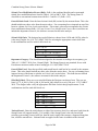
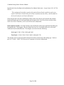
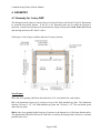
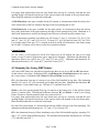
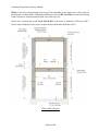
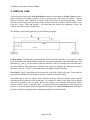
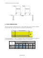
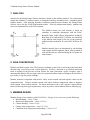
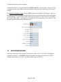
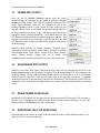
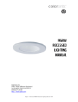
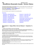
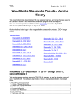
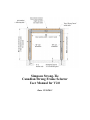
Simpson Strong-Tie Canadian Strong Frame Selector User Manual for V2.0 Date: 12/26/2013 Canadian Strong Frame Selector Manual TABLE OF CONTENTS 1. 2. 3. 4. 5. 6. 7. 8. 9. 10. 11. 12. 13. 14. 15. 16. OVERVIEW .............................................................................................................. 3 GETTING STARTED .............................................................................................. 3 DESIGN CRITERIA ................................................................................................ 3 GEOMETRY ............................................................................................................. 6 VERTICAL LOAD ................................................................................................... 9 LOAD COMBINATIONS ...................................................................................... 10 ANALYSIS .............................................................................................................. 13 SIGN CONVENTIONS .......................................................................................... 13 MEMBER DESIGN ................................................................................................ 13 CONNECTION DESIGN....................................................................................... 14 ANCHORAGE SOLUTIONS ................................................................................ 15 ANCHORAGE DESIGN ........................................................................................ 17 FRAME PDF OUTPUT ......................................................................................... 18 ANCHORAGE PDF OUTPUT.............................................................................. 18 DRAW FRAME IN AUTOCAD ........................................................................... 18 ADDITIONAL HELP OR QUESTIONS ............................................................. 18 Page 2 of 18 Canadian Strong Frame Selector Manual 1. OVERVIEW The Strong Frame Moment Frame Selector software (Strong Frame Selector) is a program that will help the Designer in selecting an appropriate frame for their given geometry and loading. Only minimum input geometries are required for the software to select an appropriate frame for the available space. Based on input geometry, the Strong Frame Selector will narrow down from the available stock frames to a handful of possible solutions. If opening dimensions are outside of stock frame sizes, the Designer can enter their specific opening dimensions and the Strong Frame Selector will provide possible custom solutions. An easy-to-use input screen and drop down menus make it simple for the Designer to input lateral and gravity loads. Both wind and seismic loads can be entered and the Strong Frame Selector will determine possible frame sizes that meet the Designer’s input requirements. Uniform, partial uniform as well as point loads can be placed anywhere along the span of the beam. Once a frame size has been selected, anchorage design is as easy as picking the foundation type, concrete strength, concrete service condition (cracked or uncracked) and grade of anchor rod. The PDF output is in a concise format that contains only important design information. However, a detailed output is also available if desired. 2. GETTING STARTED Open the software by clicking on the Strong Frame Selector icon. Enter the required Job name and user information on the top of the screen. Select from “Select a Frame to Add” drop down button to add either One Story OMF or Two Story OMF frame to design. After entering all the Design Criteria and Search has been performed, the frame can then be added to the “Configured Frames” list; From here select Save or Save As to save the file to the desired location. 3. DESIGN CRITERIA Following is a list of the input variables under the Design Criteria window on the Frame Design Tab: Design Code: 2010 National Building Code of Canada (NBCC 2010) Page 3 of 18 Canadian Strong Frame Selector Manual Seismic Force Modification Factors (RdRo): RdRo is the combined ductility and overstrength related force modification factor listed in Table 4.1.8.9 in NBCC 2010. The Strong-Frame is classified as conventional construction with Rd=1.5 and Ro=1.3 (RdRo=1.95). Lateral Seismic Load: Enter the lateral seismic load (kN) resisted by the moment frame. This value should include any shear value from the stories above. For overturning forces imposed on top of the beam or column, see Point Loads section below. This seismic value must correspond to the seismic force modification factors RdRo=1.95 (see Seismic Force Modification Factors above) and does not include the Importance Factor IE, the software accounts for this in the analysis. Seismic Drift Limit: The designer has two drift limits to choose from: 0.02hs and 0.025hs, where hs is the storey height. See 4.1.8.13(3) NBCC 2010 for selecting the appropriate seismic drift limit. Load combinations used for seismic drift check are: 1.0D + 1.0E ISLS 1.0D - 1.0E ISLS 1.0D + 1.0E ISLS + 0.5L + 0.25S ISLS 1.0D - 1.0E ISLS + 0.5L + 0.25S ISLS Importance Category: The classification assigned to the structure according to its occupancy, per Table 4.1.2.1 NBCC 2010 (Low, Normal, High). The Strong Frame is not permitted for use with Post-disaster structures under seismic loading per 4.1.8.10(2) NBCC 2010. Lateral Wind Load: Enter the specified (unfactored) lateral wind load to be resisted by the moment frame. This value should include any shear value from the stories above. For any overturning forces imposed on top of the beam or column, see Point Loads section below. This load does not include the Importance Factor Iw, the software accounts for this in the analysis. Wind Drift Limit: There are seven wind drift limits the Designer can choose from. They are: no limit, hs/175, hs/200, hs/300, hs/400, hs/500 and hx/600; default is set to hs/500 per 4.1.3.5(3) NBCC 2010. The designer must verify the appropriate drift limit for their design requirements. Load combinations used for wind drift check are: 1.0D + 1.0W ISLS 1.0D - 1.0W ISLS 1.0D + 1.0W ISLS + 0.5L 1.0D - 1.0W ISLS + 0.5L 1.0D + 1.0W ISLS + 0.5S ISLS 1.0D - 1.0W ISLS + 0.5S ISLS Notional Loads: Enter the total tributary weight of the structure (dead, live and snow loads) that the Strong Frame will support laterally. For example, if the Strong Frame is the only lateral load resisting system along a braced wall line, then the total weight of the structure, supported along that line, would be entered here. Notional loads are applied to the frame in addition to the factored Page 4 of 18 Canadian Strong Frame Selector Manual lateral loads when checking load combinations for ultimate limit states. As per clause 8.4.1 of CSA S16-09: “The translational load effects produced by notional lateral loads, applied at each storey, equal to 0.005 times the factored gravity loads contributed by that storey, shall be added to the lateral loads for each load combination.” If the designer does not enter information in these fields, the software will calculate the notional loads based on the gravity loads specified by the designer in the Load Distribution window times 0.005. See CISC Commentary on CSA S16-09 for more information. Beam Deflection Limits: For longer frames, beam deflection can become significant depending on the applied load. The designer can select limits based on Live Load deflections (live, snow and wind) and Total Load deflections. The designer can select from the following: Live Load: L/240, L/360, L/480 and L/600 Total Load: L/180, L/240, L/360, L/480, L/600 and L/720 The designer must verify beam deflection limits based on construction and loading type. Refer to the User’s Guide - NBCC 2010 Structural Commentaries for more information. Page 5 of 18 Canadian Strong Frame Selector Manual 4. GEOMETRY 4.1 Geometry for 1-story OMF The Designer has the option to choose from a list of stock frames with fixed W1 and H1 dimensions by using the drop down buttons. If the W1 or H1 dimension does not fit within the Designer’s geometry, custom frame design can be performed by simply clicking the Custom Frame Size button and entering the desired W1 and H1 values. Following is a list of input variables under the Geometry Section: Stock Frames: W1 is the clear opening width from the inside face of 2x wood nailers for each column. H1 is the dimension from top of concrete to top of the field installed top plate. The dimension includes 38.1mm (1-1/2”) for field-installed top plate and 38.1mm (1-1/2”) for non-shrink grout under the base plate. Hmin is the clear opening height from top of concrete to the bottom face of the beam bottom nailer. The dimensional difference between H1 and Hmin is used by the Strong Frame Selector to calculate possible beam sizes. Page 6 of 18 Canadian Strong Frame Selector Manual For garage front applications where the steel frame bears on top of a concrete curb and the clear opening height is measured from the top of the concrete slab to the bottom of the steel beam nailer, Hmin should be adjusted to exclude the curb height. A Wall Dimension is the space available for the left column. It is dimensioned from the interior face of the inside nailer of the left column to the edge of the next opening/end of wall. B Wall Dimension is the space available for the right column. It is dimensioned from the interior face of the inside nailer of the right column to the edge of next opening/end of wall. Minimum of A and B wall dimensions is used by the Strong Frame Selector to calculate possible column sizes. Column dimensions including wood nailers are 228.6 mm (9”) for C6, 304.8 mm (12”) for C9, 381 mm (15”) for C12, 457.2 mm (18”) for C15, 534 mm (21”) for C18H and 610 mm (24”) for C21H. For example when 304.8 mm (12”) is entered for both A and B wall dimensions, only frames using the C6 and C9 columns will be shown on the list of possible solutions. Custom Frames: W1, H1, Hmin, A Wall Dimension and B Wall Dimension are all defined the same as for stock frames, except W1 and H1 dimensions can be input by the Designer. Minimum and Maximum W1 dimension allowed are 1828.8 mm (72”) and 5715 mm (225”). Minimum and Maximum H3 dimension allowed are 2197.1 mm (86.5”) and 6426.2 mm (238.5”). 4.2 Geometry for 2-story OMF frames: All 2-story OMF frames are considered custom design; there are no pre-set W1 and H1 dimensions for the users to select from. Definition of W1, A wall dimension, B wall dimension are the same as the 1-story frames. Definition of H1, H1min, D, H2 and H2min are noted below: H1 is the dimension from top of concrete to top of the field installed 2x top plate. The dimension includes 38.1 mm (1-1/2”) for non-shrink grout under the base plate. Minimum and Maximum H1 dimension for 2-story OMF frames are: 1828 mm (72”) and 6096 mm (240”). H1min is the clear opening height from top of concrete to the bottom face of the mid-level beam (beam 1) bottom nailer. Dimensional difference between H1 and H1min is used by the Strong Frame Selector to calculate possible beam sizes at the mid-level. For garage front applications where the steel frame bears on top of a concrete curb and the clear opening height is measured from the top of the concrete slab to the bottom of the steel beam nailer, Hmin should be adjusted to exclude the curb height. D is the floor system depth. It’s measured from the top of H1 to the top of the floor sheathing. The minimum and maximum dimensions are: 12.7 mm (½”) to 610 mm (24”). H2 is the dimension from top of floor sheathing to top of the field installed top plate, assuming 38.1 mm (1-1/2”) for the field installed top plate. The minimum and maximum dimensions are: 1828 mm (72”) and 6096 mm (240”). Page 7 of 18 Canadian Strong Frame Selector Manual H2min is the clear opening height from top of floor sheathing to the bottom face of the top-level beam (beam 2) bottom nailer. Dimensional difference between H2 and H2min is used by the Strong Frame Selector to calculate possible beam sizes at the top level. Please note, currently the overall height (H1+D+H2) of the frame is limited to 10668 mm (420”). Please contact Simpson if your project requires frames taller than 10668 mm (420”). 2-Story OMF Geometry Page 8 of 18 Canadian Strong Frame Selector Manual 5. VERTICAL LOAD Vertical loads are input in the Load Distribution window located under the Design Criteria window. Sign convention for loading is positive in the gravity direction, and negative for uplift. Uniform loads are in kN per meter, and may be the full width of the frame or may be partial loads. 5 basic load cases can be entered into the Strong Frame Selector software as follows: Dead Load (DL), Live Load (LL), Snow, Wind and Seismic. All loads must not include the Importance Factor, the software accounts for this in the analysis. The loading is represented graphically by the following diagram: Uniform Loads: The Designer can input uniform loads for Dead Load (DL), Live Load (LL), Snow Load, and Wind load. Partial uniform loads can start and end anywhere within the beam span. The dimensions XL and XR are the distance from the centerline of the left column to the start and end of the partial uniform load, respectively. Strong Frame Selector will ignore any loads past the end of the beam. Click on “To RCC” to load the beam to the Right Column Centerline Point Loads: Up to 8 point loads can be entered for each of the 5 basic load cases. Point loads are specified in kN followed by the distance from the centerline of the left column. Point loads due to wind or seismic from shearwall reactions above the moment frame must be consistent with the direction of the lateral load. For example, P1 and P3 in the figure below shall be entered with a negative value for uplift. The selector software will switch the direction of P1 and P3 to positive and P2 and P4 to negative and V1 to negative thru load combinations so the Designer do not have to do two designs by switching the load directions. See Load Combinations Section below for more information regarding load combination and direction of lateral loads. Page 9 of 18 Canadian Strong Frame Selector Manual V2a V2b Shearwall Shearwall P1 P3 Right Column P4 Beam Left Column V1 P2 6. LOAD COMBINATIONS The five basic load cases defined above (DL, LL, Snow, Wind, and Seismic) are used for combining loads Per NBCC 2010. The basic load cases are summarized in the tables below: Load Combinations D Basic ID 1 2 3 4 5 L S W E For load combinations, IULS and ISLS are importance category factor for strength and serviceability as noted in the tables below. Ni is the notional load per clause 8.4.1 of CSA S16-09. Importance Factor Category Low Normal High IULS Strength (ULS) ISLS Serviceability (SLS) S W E S W E 0.8 0.8 0.8 0.9 0.75 0.8 1 1 1 0.9 0.75 1 1.15 1.15 1.3 0.9 0.75 1.3 Page 10 of 18 6 1.4D + Ni 7 1.25D + 1.5L+ Ni 8 1.25D + 1.5L + 0.5S IULS + Ni 9 1.25D + 1.5L + 0.4W IULS + Ni 10 1.25D + 1.5L - 0.4W IULS - Ni 11 0.9D + 1.5L + Ni 12 0.9D + 1.5L + 0.5S IULS + Ni 13 0.9D + 1.5L + 0.4W IULS + Ni 14 0.9D + 1.5L - 0.4W IULS - Ni 15 1.25D + 1.5S IULS + Ni 16 1.25D + 1.5S IULS + 0.5L + Ni 17 1.25D + 1.5S IULS + 0.4W IULS + Ni 18 1.25D + 1.5S IULS - 0.4W IULS - Ni 19 0.9D + 1.5S IULS + Ni 20 0.9D + 1.5S IULS + 0.5L + Ni 21 0.9D + 1.5S IULS + 0.4W IULS + Ni 22 0.9D + 1.5S IULS - 0.4W IULS - Ni 23 1.25D + 1.4W IULS + Ni 24 1.25D - 1.4W IULS - Ni 25 1.25D + 1.4W IULS + 0.5L + Ni 26 1.25D - 1.4W IULS + 0.5L - Ni 27 1.25D + 1.4W IULS + 0.5S IULS + Ni 28 1.25D - 1.4W IULS + 0.5S IULS - Ni 29 0.9D + 1.4W IULS + Ni 30 0.9D - 1.4W IULS - Ni 31 0.9D + 1.4W IULS + 0.5L + Ni 32 0.9D - 1.4W IULS + 0.5L - Ni 33 0.9D+ 1.4W IULS + 0.5S IULS + Ni 34 0.9D - 1.4W IULS + 0.5S IULS - Ni 35 1.0D + 1.0E IULS + Ni 36 1.0D - 1.0E IULS - Ni 37 1.0D + 1.0E IULS + 0.5L + 0.25S IULS + Ni 38 1.0D - 1.0E IULS + 0.5L + 0.25S IULS - Ni Strength Canadian Strong Frame Selector Manual Strength Combinations Used for Frame Member Design Page 11 of 18 39 1.0D 40 1.0D + 1.0L 41 1.0D + 1.0L + 0.5S ISLS 42 1.0D + 1.0L + 0.4W ISLS 43 1.0D + 1.0L - 0.4W ISLS 44 1.0D + 1.0S ISLS 45 1.0D + 1.0S ISLS + 0.5L 46 1.0D + 1.0S ISLS + 0.4W ISLS 47 1.0D + 1.0S ISLS - 0.4W ISLS 48 1.0D + 1.0W ISLS 49 1.0D - 1.0W ISLS 50 1.0D + 1.0W ISLS + 0.5L 51 1.0D - 1.0W ISLS + 0.5L 52 1.0D + 1.0W ISLS + 0.5S ISLS 53 1.0D - 1.0W ISLS + 0.5S ISLS 54 1.0D + 1.0E ISLS 55 1.0D - 1.0E ISLS 56 1.0D + 1.0E ISLS + 0.5L + 0.25S ISLS 57 1.0D - 1.0E ISLS + 0.5L + 0.25S ISLS Serviceability Canadian Strong Frame Selector Manual Serviceability Combinations Used for Deflection and Drift Check Page 12 of 18 Canadian Strong Frame Selector Manual 7. ANALYSIS Analysis for the Strong Frame Selector Software is based on the stiffness method. For each element (beam and columns), a stiffness matrix is determined and then assembled into a combined global stiffness matrix. After applying boundary conditions (pinned based columns), the Strong Frame Selector solves for the overall displacement matrix. From the displacement matrix, member end forces are determined for each of the elements. The stiffness matrix for each element is based on centerline to centerline dimensions with the EulerBernoulli beam model (Shear deformations included). Both large (P-) and small (P-P-Delta are considered in the analysis and design by the use of the geometry stiffness matrix method for P- and AISC B1 factor for P- Member internal forces are determined by sub-dividing each element into100 segments. Shear, axial, moment as well as deflection are calculated along the 101 points for each element. 8. SIGN CONVENTIONS Default coordinate system is the 2D Cartesian coordinate system with x-axis being in the horizontal direction and y-axis being in the vertical direction. Positive y-direction is up (uniform and point loads as defined in the previous section follows the same convention, except a negative sign is automatically added to the user input values for point and uniform loads so Designers do not have to type in the (-) sign for gravity loading). Member moment is outputted with positive values on the tension side and negative values on the compression side. Positive column reaction axial values indicate compression where as negative axial reaction values indicate tension. For beam deflection in the y-axis, negative values indicate beam is deflecting down (gravity direction), where as positive values indicate beam is deflecting up. 9. MEMBER DESIGN Member design is in accordance with CSA S16-09 – Design of steel structures per the following: Beam bending – clause 13.6(a) Beam axial compression – clause 13.3.2(a) Column bending – clause 13.6(e) Column axial compression – clause 13.3.2(b) Combined axial compression and bending – clause 13.8.2 Page 13 of 18 Canadian Strong Frame Selector Manual Shear – clause 13.4.1.1 The maximum demand-to-capacity ratio (DCR) for all members is limited to 1.01. The same maximum DCR ratio applies to wind and seismic deflection limits as well as connection and anchorage design (see following section). 10. CONNECTION DESIGN End plate moment connection capacities were calculated based on the CISC design guide - Moment Connections for Seismic Applications (2009). These capacities were pre-calculated base on the beam and column connection geometries. Capacity values are used to compare to the force demand for each of the factored load combinations. Base plate capacities were calculated based on AISC Design Guide 1 – Base Plate and Anchor Rod Design. These capacities were pre-calculated based on column geometry. Base plate tension, shear and axial capacities are used to compare to the force demand for each of the factored load combinations. Beam top flange nailer capacities have been calculated in accordance with CSA O86-09. All connection design calculations can be viewed and printed under the Resource tab located on the main tool bar of the Strong-Frame Selector software. Page 14 of 18 Canadian Strong Frame Selector Manual 11. ANCHORAGE SOLUTIONS After a frame model has been selected, the Anchorage Design tab becomes active and the Designer can chose anchorage solutions based on Foundation Type. The three foundation types are described below, and are selected from a drop down menu: For Slab-on-Grade Foundation Types, there are two solutions the Designer can choose from; they are MFSL and MFAB with Hairpins. Input fields required for the MFSL and MFAB with Hairpins are: Step Height: Height from top of concrete footing to top of concrete slab. This dimension is used for determining the length of anchor rod required for anchorage. Page 15 of 18 Canadian Strong Frame Selector Manual Concrete Strength (fc’): The Designer can choose 20 MPa, 25 MPa, or 30 MPa as the concrete strength. The concrete strength is used for determining the anchorage tension and shear capacities. Anchor Rod Grade: Two anchor rod grades are available to the Designer, either ASTM F1554 Gr. 36 or ASTM A449. Anchorage solution using A449 include “HS” in their designation to denote high strength. IEFaSa(0.2) ≥ 0.35: When load combinations include seismic effects under the condition IEFaSa(0.2)≥0.35, the ductility provisions of clause D.4.4.3 CSA A23.3-04 (2009) apply. When the designer selects “Y” in this field, the Strong Frame Selector software will account for this in the calculations. Concrete (service condition): The Designer can choose either Cracked or Uncracked as the service concrete condition. Condition: The Designer can choose either Condition A or Condition B. If condition B is selected a factor of 1.0 is applied to the concrete tensile capacity. If condition A is selected a factor of 1.15 is applied to the concrete tensile capacity. Per clause D.5.4(c) CSA A23.3-04 (2009): “Condition A applies where the potential concrete failure surfaces are crossed by supplementary reinforcement proportioned to tie the potential concrete failure prism into the structural member. Condition B applies where such supplementary reinforcement is not provided or where pullout or pryout strength governs.” For Curb/Brick Ledge Foundation Types, two solutions are available for the Designer. They are MFSL and MFAB with Ties. Input fields for these solutions are similar to the Slab-on-Grade solutions, except Curb Height is required instead of Step Height. One additional input is the Curb Width. Under this drop down box, the Designer can choose either a 200 mm, 250 mm or 300 mm wide concrete curb. Page 16 of 18 Canadian Strong Frame Selector Manual If small end distances are required/desired, the MFAB with Ties is the best option. However, it has a minimum 64 mm edge distance from the centerline of the outer most anchor bolt to the edge of concrete. For Stemwall Foundation Types, only the MFSL solution is available to the Designer. However, this requires Designer to design wall reinforcing to transfer forces from the base of the column down to the foundation. Capacity of the anchor rods, shear lug, hairpin, ties and concrete are included in the solution PDF output. Anchorage force demands are also summarized in the solution so the Designer can perform their own anchorage design. 12. ANCHORAGE DESIGN Anchorage solutions have been designed in accordance with CSA A23.3-04 (2009), including the provisions of Annex D. The OMFSL solution incorporates the design provisions of CSA N287.3 with the requirements of CSA A23.3-04 (2009) and the intent of Annex D. Page 17 of 18 Canadian Strong Frame Selector Manual 13. FRAME PDF OUTPUT Once the list of Possible Solutions appears after the frame analysis/design, the Designer has the option to generate a Design Summary in PDF format. This PDF file contains a summary of the design input parameters entered by the Designer as well as the loading information on the 1st page. On the 2nd page, all the relevant demand capacity ratios are presented for the frame design followed by the governing design forces. Page 3 summarizes the frame design with all the frame geometry dimensions. Note that the final W1 and W2 dimensions depend on the foundation anchorage solution. The Designer must refer to the Anchorage output for the final W1 and W2 dimensions where additional end distances might be required for anchorage design. Detailed output includes the Design Summary described above followed by member properties, frame analysis geometries, member nodal displacements, beam forces, column forces, beam member design, column member design from all the design load combinations and column reaction forces for the 5 basic load cases. 14. ANCHORAGE PDF OUTPUT Similar to the Frame PDF output, anchorage design output can be generated by the push of the Design Output button in the Anchorage Design tab. The anchorage design PDF file summarizes the anchorage model, footing width and footing depth required for anchorage as well as end distance required from the centerline of the nearest anchor bolt to the edge/end of concrete. In addition anchorage design forces and anchorage capacities are summarized. On the last page of the PDF file, foundation forces for both left and right column are output to aid the Designer in their foundation design. 15. DRAW FRAME IN AUTOCAD In addition to PDF outputs, the Designer can also generate an AutoCAD elevation. The elevation is drawn to scale so Designers can simply insert the frame elevation into their drawing. See the CAD Help document under Resources for more information. 16. ADDITIONAL HELP OR QUESTIONS If information beyond what is provided in this document is needed, contact Simpson Strong-Tie at (800) 999-5099 or www.strongtie.com. Page 18 of 18