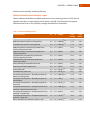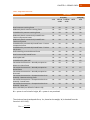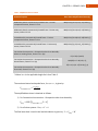
1
LF10
LF10 User’s Manual
LF10 USER'S MANUAL
Lateral Forces 2010
LF10 User’s Manual
User’s Manual
Lateral Forces 2010
First Edition, September 2011
Copyright © 2011
All rights reserved.
This manual or any part thereof must not be reproduced in any form without the written permission
of the publisher.
ISBN 978-0-88811-150-0
Canadian Institute of Steel Construction
3760 14th Avenue, Suite 200
Markham, Ontario L3R 3T7
Tel: (905) 946-0864
Email: [email protected]
Website: www.cisc-icca.ca
PREFACE
PREFACE
Prepared by the Canadian Institute of Steel Construction (CISC), the Lateral Forces 2010
(LF10) Excel spreadsheets for Wind and Seismic Loads replace the Lateral Forces 90 (LF90)
program of the CISC Steel Design Series for the IBM Personal Computer and compatibles.
The Microsoft Excel spreadsheets are part of a continuing effort by the Canadian structural
steel industry to simplify the design of steel structures. Accordingly, LF10 joins the
Handbook of Steel Construction and other design aids made available to designers by the
Canadian Institute of Steel Construction.
LF10 is based on the requirements of the National Building Code of Canada 2010, the
Supplement to the National Building Code of Canada 2010 and CSA S16-09 Design of Steel
Structures. The user must understand the design requirements of these documents before
attempting to use the LF10 spreadsheets.
In addition to explaining how to use the spreadsheets, this manual contains information
relating to the design procedures and assumptions incorporated into the spreadsheets.
Thus the designer will recognize the capabilities and limitations of the spreadsheets and,
through the various options available, interject personal design requirements or
engineering judgement.
LF10 has been tested extensively and to the best of our knowledge, all data and information
contained in both the spreadsheets and this manual were correct at the time of publication.
The Canadian Institute of Steel Construction does not assume any responsibility for errors,
misinterpretations or oversights resulting from the use of the Lateral Forces 2010
spreadsheets or this manual.
Canadian Institute of Steel Construction
3
4
LF10 User’s Manual
TABLE OF CONTENTS
PREFACE .................................................................................................................................... 3
TABLE OF CONTENTS................................................................................................................. 4
CHAPTER 1 – PURPOSE ............................................................................................................. 7
CHAPTER 2 – GENERAL.............................................................................................................. 9
Hardware and Software Requirements ................................................................................ 9
Accessing the Spreadsheets .................................................................................................. 9
Design Standard .................................................................................................................... 9
Units .................................................................................................................................... 10
Data Input ........................................................................................................................... 10
Error Checking ..................................................................................................................... 10
Problem Size Limitations..................................................................................................... 10
Geometry and Sign Conventions ........................................................................................ 10
Output ................................................................................................................................. 11
Limitations........................................................................................................................... 12
Spreadsheet Protection ...................................................................................................... 12
Printing Reports .................................................................................................................. 12
CHAPTER 3 – WIND LOADS ..................................................................................................... 13
Lateral wind loads on the entire building – “Wind” sheet ................................................. 13
Reset Button ................................................................................................................... 13
Project information ......................................................................................................... 13
Level heights and dimensions - Input ............................................................................. 13
Site, importance category and terrain – Input ............................................................... 14
NBC climatic wind data and user-specified wind pressure ............................................ 14
Limit state, type of procedure and Building on hill – Input ............................................ 15
Forces and overturning on building – Output ................................................................ 15
CHAPTER 4 – SEISMIC LOADS .................................................................................................. 17
Reset Button ................................................................................................................... 17
Project Information ............................................................................................................. 17
Level Heights and Weights - Input ...................................................................................... 17
TABLE OF CONTENTS
Site and Class - Input ........................................................................................................... 18
NBC site parameters and user-specified spectral accelerations .................................... 18
SFRS and Period for the X-direction - Input ........................................................................ 19
Forces and Distribution (X-direction) – Output .................................................................. 20
Force Multiplier for Deflection Calculations (X-Direction) ................................................. 24
Seismic Loads Calculations (Y-Direction) ............................................................................ 24
APPENDIX A – TECHNICAL NOTES (WIND) .............................................................................. 25
Effective Building Width ..................................................................................................... 25
APPENDIX B – TECHNICAL NOTES (SEISMIC) .......................................................................... 27
Method of Analysis, NBC 4.1.8.7 ........................................................................................ 27
SFRS General Restrictions, NBC 4.1.8.9 .............................................................................. 27
Post-Disaster Buildings, NBC 4.1.8.10 ................................................................................. 27
5
6
LF10 User’s Manual
CHAPTER 1 – PURPOSE
CHAPTER 1 – PURPOSE
The CISC Lateral Forces 2010 spreadsheets (LF10) have been developed to compute lateral
forces due to wind and/or earthquake according to the 2010 National Building Code of
Canada. There are two separate spreadsheets for Wind and Seismic loads. Both use the
same format for input and output.
The Wind module (LF10-Wind) determines wind storey forces in each direction in
accordance with either the Static Procedure for High-Rise or the Dynamic Procedure, which
are given in Commentary I of the Structural Commentaries (Part 4 of Division B) to the
National Building Code of Canada, 2010. The Speed-up over hills and escarpments is
implemented.
The Earthquake module (LF10-Seismic) determines seismic storey forces in accordance with
the Equivalent Static Force Procedure of the NBC including Commentary J of the Structural
Commentaries (Part 4 of Division B) to the National Building Code of Canada, 2010 and CSA
S16-09.
Design assumptions built into the spreadsheets have been kept to a minimum. When an
assumption is made it is documented in the spreadsheets and in this manual. In this way the
designer has complete control over the calculations.
To facilitate validation and verifications, where possible and relevant, intermediate results
are available and can be displayed as an option.
7
8
LF10 User’s Manual
CHAPTER 2 – GENERAL
CHAPTER 2 – GENERAL
Prior to using the Lateral Forces 2010 spreadsheet, it is advisable to become familiar with a
brief list of the spreadsheet's capabilities, features, and limitations. They are as follows:
Hardware and Software Requirements
The Microsoft Excel spreadsheet requires a version of Microsoft Excel be installed. The
spreadsheet was optimized for use with Microsoft Excel 2007.
Macros must be enabled to display more than the Welcome screen. To enable macros, go to
“Excel options” → “Trust Center” → “Trust Center Settings” → “Macro Settings” and click
on “Enable all macros”. You will then need to restart Excel for the new setting to be
considered.
To disable the Privacy warning that might be shown by Excel, go to “Developer Ribbon”,
click “Macro Security”, click “Privacy Options” and uncheck all notifications.
Accessing the Spreadsheets
When you access the LF10 spreadsheets, either the Wind or Seismic module, the first
worksheet you will encounter is the "Welcome" sheet containing an Introduction and
Disclaimer. In order to proceed, you will need to obtain your Activation Key from CISC by
following the instructions on the CISC website (www.cisc-icaca.ca).
Type in your Activation Key in the cell at the bottom of the window and click the "ACCEPT
DISCLAIMER AND ENTER" button to acknowledge the software license. You may save the
workbook with your Activation Key to avoid having to enter it again in the future.
As you access the spreadsheet, "zoom" settings for the different sheets are automatically
adjusted to the window size.
Design Standard
Design standards include the National Building Code of Canada 2010 and the Structural
Commentaries (Part 4 of Division B) to the National Building Code of Canada 2010. Seismic
force increases based on the type of SFRS and the building height are determined according
to CSA S16-09.
9
10
LF10 User’s Manual
Units
The International System of Units (SI), is used exclusively in LF10. The required units for
each item of input data is given as the data is requested. In general, the units and
abbreviations are as follows:
length
area
force
area load
moment
metres (m)
square metres (m2)
kilonewtons (kN)
kilopascals (kPa)
kilonewton metres (kN·m)
Data Input
The building geometry and design parameters are input using tables, cells and drop-down
menus which appear on the screen. Data can be typed into the tables, pasted or dragged
and copied from one cell to others. Input cells and drop-down menus are on a white
background.
Figure 1 - Input cell
Error Checking
During data input, possible errors are checked for input data type (e.g. words entered
where a number is required) or data outside the normal range. When an error is found, a
brief description is displayed, and the user is prompted to correct the input. To allow
maximum flexibility, the permissible range of input values is wide. For example, when
entering the period, Ta (mechanics), a decimal value between 0.1 and 99 must be entered.
Figure 2 - Error warning for invalid data
Problem Size Limitations
The LF10 spreadsheet can compute forces for buildings up to 100 levels in height.
Geometry and Sign Conventions
The building geometry is specified in LF10 by entering the height, width and length of each
level (Wind module only) and then stacking the levels vertically. The levels are numbered in
ascending order starting at the bottom of the building with level number zero being ground.
LF10-Seismic permits buildings with SFRS located along orthogonal axes only. Refer to the
NBC for buildings for other SFRS orientations.
CHAPTER 2 – GENERAL
Building geometry and dimensions conventions in LF10 are shown on Figure 3.
Wind Load
X direction
wx
TYPICAL LEVEL
wy
y Building envelope reference
x
Wind Load
Y direction
Figure 3 - Building dimensions
Wind forces act through the centre of geometry, while earthquake forces act through the
centre of mass at each floor level.
Output
Output load tables are given by load type and principal building direction. In every load
table generated, the output includes the lateral force, the cumulative shear and the
cumulative overturning moment at the base of each level. The results of intermediate
calculations are available and can be displayed by clicking the “check calculations” button,
as shown on Figure 4.
Figure 4 - Check calculations button
All wind loads are factored. For design purposes, wind loads can be compared directly to
the earthquake forces. Output is given in cells with a light yellow background.
The level output is given as illustrated on Figure . While the applied force is at the top of a
level, the overturning moment and shear for that level are at the base:
11
12
LF10 User’s Manual
Level
Roof
...
3
2
1
Base
Froof
F3
F2
F1
V4
M4
V3
M3
V2
M2
V1
M1
Figure 5 - Level output
Limitations
The spreadsheet can calculate lateral loads for buildings rectangular in plan only, and with
flat roofs. Irregular building shapes must be approximated by a rectangular model. The
building length and width may change from level to level, but any level rotated in the
horizontal plane (about the vertical axis) must be approximated by a non-rotated level by
the design engineer.
The spreadsheet will not perform a structural analysis or a dynamic analysis.
The purpose of the spreadsheet is not to replace calculations performed by a design
engineer, but to assist the engineer in computing lateral loads. It would be impractical to
provide a complete, step-by-step illustration of wind or earthquake calculations, whether
the design is performed manually or by means of a spreadsheet. Therefore, output from
LF10 provides sufficient key information about each load combination, so that the results
can be easily verified by a qualified design engineer. It is left to the design engineer to verify
load calculations and judge their applicability with respect to design criteria.
Spreadsheet Protection
The spreadsheet is protected – some cells cannot be modified but can be selected, for
example to copy the results.
Printing Reports
Excel printing options can be used to print reports. It is recommended to adjust the position
of page breaks according to the number of levels in the building.
CHAPTER 3 – WIND LOADS
CHAPTER 3 – WIND LOADS
LF10-Wind can calculate lateral wind loads either according to the static procedure for highrise buildings or the dynamic procedure. The user is responsible for choosing the
appropriate method. Ultimate limit states and serviceability limit states can be considered
separately. The wind is assumed to act in either of the two principal building directions
through the centre of geometry of the given level. Only horizontal loads are computed;
vertical wind pressures acting on the roof are not included. And only overall loads acting on
the entire building's lateral load-resisting system are computed. The applicability of the
Static or Dynamic Procedure is not checked by LF10-Wind. (See Article 4.1.7.2 and Figure
I-1)
Wind forces generated by the spreadsheet are to be used for strength and deflection design
of structural lateral load-resisting systems; they are not applicable to the design of cladding.
In LF10-Wind, the internal pressure, pi, is not considered to affect loads on the building
structure since the windward and leeward faces are assumed to be vertical and identical for
each direction. The need to consider internal pressure, pi, should be reviewed by the project
engineer.
Lateral wind loads on the entire building – “Wind” sheet
This sheet performs load calculations for the entire building without consideration of
torsion. Partial or unbalanced load conditions are not included.
Reset Button
Click on the Reset button to initialize the input data.
Project information
The user can enter the date, a project designation and fill the “prepared by” box to identify
projects on the screen and on a printed report. The contents of those fields are not used by
the spreadsheet.
Level heights and dimensions - Input
The number of levels must be an integer from 1 to 100. This value is used to adjust the
number of data cells for input and output. A minimum of 8 levels is shown. Please note that
if the number of levels is changed after entering the level data, all data previously entered
for levels above the new number will be lost.
The inter-storey height (hs) for each level must be a decimal value in metres between 0.1
and 99.
DX is the building width at a given level for wind loading acting in the X direction, and DY is
the width for wind loading in the Y direction. These dimensions are used in the calculation
13
14
LF10 User’s Manual
of tributary areas. They should be representative of the entire building envelope and thus
include the thickness of cladding.
A roof parapet with a height of up to 1.5 m can be added to the roof level. The parapet
dimensions in the X and Y directions are the same as the dimensions of the roof level. The
parapet is not included in the building height for subsequent calculations.
Optionally, dimensions at the base, the total height and effective widths in both directions
can be displayed. Effective widths are calculated according to NBC Article 4.1.7.2.
Site, importance category and terrain – Input
LF10 – Wind incorporates the climatic data from Appendix C of the NBC 2010. Both the
province and the city are listed alphabetically. Note that cities which are part of a
metropolitan region are not grouped as in Appendix C. Thus, for example, North York will
not be listed under Toronto but under its own name.
The province and location of the building are selected by means of a drop-down menu. The
location list is updated when the province is changed. When the province is changed, the
first location name is initially selected. The Reference velocity pressure q1/50 is the one given
in Appendix C.
The importance category of the building is selected through a drop-down menu. Available
choices are given in NBC Table 4.1.7.1.
The terrain type is also selected through a drop-down menu. Open terrain exposure
(Exposure A) and Rough terrain exposure (Exposure B) can be selected. Exposure C in the
dynamic procedure of the NBC is not implemented in LF10-Wind. Exposure C should be
used with caution and only in the centre of large cities. LF10-Wind does not permit
interpolation between exposures.
NBC climatic wind data and user-specified wind pressure
The user may select a user-specified pressure by checking the box located directly under the
Reference velocity pressure input box. Alternatively, the NBC 2010 climatic wind data for
the location may be used (by unchecking the box).
CHAPTER 3 – WIND LOADS
Limit state, type of procedure and Building on hill – Input
The limit state for calculating wind loads is selected through a drop-down menu. Ultimate
limit states and Serviceability limit states are the available selections, which will affect the
value of the Importance factor, IW, according to Table 4.1.7.1.
The desired procedure for wind load calculation is selected through another drop-down
menu. No additional input is necessary for the Static Procedure. If the Dynamic Procedure is
selected, the user must input β, the critical damping ratio for the building, and natural
frequencies of vibration fnD,X and fnD,Y for the X and Y directions, respectively. It is noted that
the empirical formulas for period calculations used in seismic design should not be used for
wind forces.
If desired, the effects of wind speed-up over hills and escarpments can be included in
accordance with paragraphs 13 to 16 and 21 of Commentary I and for both the Static and
Dynamic Procedures. The choice of hill and escarpment shape and parameters for
maximum speed-up is given according to Table I-1. If a hill or escarpment is selected, the
user must also input:
•
•
•
Hh, the height of the hill or escarpment or the difference in elevation between the
crest and the terrain surrounding the hill or escarpment upwind. Negative values of
Hh are beyond the scope of LF10-Wind.
Lh, the distance upwind of the crest to where the ground elevation is half of Hh
x, a horizontal distance from the crest
The spreadsheet includes figures describing the hill or escarpment geometry as needed.
Only one amplification factor for speed-up is considered for the entire building. If a hill is
specified, the speed-up will affect both the X and Y directions. Also, conservatively, the
same x distance is used for the windward and the leeward faces of the building.
Optionally, the user can display the factors used for the calculation of Ce*/Ce. The maximum
speed-up factor at the base level of the building (i.e. at the top of the hill) is also provided.
Forces and overturning on building – Output
By clicking the “check calculations” button below the title of the section, the user can
display the values of Cp, Ce (or Ce*) and Cg (or Cg*) used in wind pressure calculations.
Values of Ce (or Ce*) and Cg (or Cg*) are given for each level. These coefficients are also
computed at an elevation above the base equal to a quarter of the height of the first level.
In the next drop-down menu, available only if Ultimate Limit States are selected, the user
must indicate whether the wind loads act as a Principal Load of as a Companion Load. This
will affect the Load factor, which is then displayed below. For Serviceability Limit States, the
load factor is invariably 1.0.
15
16
LF10 User’s Manual
The output of this sheet is presented in the form of a table of applied forces (F), shears (V)
and overturning moments (M), for each direction and level. For each level, the output is
given as illustrated on Figure 6. While the applied force is at the top of a level, the
overturning moment and shear given for that level are referred to its base.
For wind force calculations, tributary areas at a given level generally include half of the level
heights immediately above and below the level. For the roof, the tributary area includes
half of the level below and the entire area of the parapet above. At the base level, the wind
on the bottom half of the first level is considered to be transmitted directly to the
foundation. This force, F0 , is only included in the output for the shear force corresponding
to the entire building at the base, for purposes of foundation design. If necessary, the value
of F0 can be calculated by subtracting the shear for level 1 from the shear of the entire
building at the base.
In calculating the overturning moment, the point of application of the wind force on the
parapet is taken at its mid-height.
Figure 6 illustrates the tributary areas and applied wind forces for the entire building.
Level
Roof
...
3
2
1
Base
parapet
Froof
F3
F2
F1
F0
Figure 6 - Tributary areas for wind forces
CHAPTER 4 – SEISMIC LOADS
CHAPTER 4 – SEISMIC LOADS
The lateral earthquake design force at the base of the structure, V, is computed and
distributed according to NBC 2010 Article 4.1.8 of the NBC 2010. The Equivalent Static Force
Procedure for Structures Satisfying the Conditions of Article 4.1.8.7 is used to determine
static loads.
LF10 – Seismic will perform load calculations for the selected location and type of Seismic
Force-Resisting System (SFRS). A warning will appear if a system not allowed by the NBC is
selected. The user should use the CISC Steel Seismic Systems software to determine which
systems are allowed for the location and building height, and to verify whether S(0.2) is less
than or equal to 0.12, in which case the requirements of Article 4.1.8 need not apply.
Reset Button
Click on the Reset button to initialize the input data.
Project Information
The user can enter the date, a project designation and fill in the “prepared by” box to
identify projects both on the screen and on a printed report. The contents of those fields
are not used by the spreadsheet.
Level Heights and Weights - Input
The number of levels must be an integer from 1 to 100. This input value is used to display
the appropriate number of data cells for input and output results. A minimum of 8 levels of
input and output are shown when a figure is used to illustrate the table. Please note that if
the number of levels is changed, all data entered for levels above the new number of levels
will be lost.
The inter-storey height (hs) for each level must be a decimal value in metres between 0.1
and 99.
'W' is the dead load, or weight, assigned to each level. The dead load is defined in Article
4.1.4.1. The dead load assigned to each level must be a positive value.
For reference and verification, both the sum of the inter-storey heights and the total dead
load are given at the bottom of the table. The input values for inter-storey height and
weight for each level are shown on Figure 7:
17
18
LF10 User’s Manual
Level
Roof
...
3
2
1
Base
Wroof
hs,roof
W3
W2
hs,3
W1
hs,2
hs,1
Figure 7 - Level height and weight input
Site and Class - Input
LF10 – Seismic incorporates the climatic data from Appendix C of the NBC 2010. Both the
province and the city are listed alphabetically. Note that cities which are part of a
metropolitan region are not grouped as in Appendix C. Thus, for example, North York will
not be listed under Toronto but under its own name.
The province and location of the building are selected by means of a drop-down menu. The
location list is updated when the province is changed. When the province is changed, the
first location name is initially selected. The spectral response acceleration values Sa(T) for
periods T of 0.2s, 0.5s, 1.0s and 2.0s are the values given in Appendix C.
The importance category of the building is selected through a drop-down menu. Available
choices are given in NBC Table 4.1.8.5, and the importance factors for ULS given in the table
are used in the spreadsheet. Note that NBC stipulates additional system restrictions to Postdisaster buildings (refer to Article 4.1.8.10).
Site classification depending on the ground profile is based on Table 4.1.8.4.A. of NBC 2010.
When Site Class F is selected, the used can directly input values of acceleration and velocitybased coefficients Fa and Fv. Refer to the NBC for more information on selecting the
appropriate Site Class.
Acceleration and velocity-based coefficients Fa and Fv are based on Tables 4.1.8.4.B. and
4.1.8.4.C. and are linearly interpolated for intermediate values of Sa(0.2) and Sa(1.0).
Values of the design spectral acceleration S(T) are determined as follows:
S(T) = FaSa(0.2) for T = 0.2 s
= FvSa(0.5) or FaSa(0.2), whichever is smaller for T = 0.5 s
= FvSa(1.0) for T = 1.0 s
= FvSa(2.0) for T = 2.0 s
= FvSa(2.0)/2 for T ≥ 4.0 s
NBC site parameters and user-specified spectral accelerations
You may enter user-specified spectral accelerations by checking the box, "Check to enter
user-specified spectral accelerations". Alternatively, the NBC 2010 seismic data for the
CHAPTER 4 – SEISMIC LOADS
19
location may be used (by unchecking the box).
SFRS and Period for the X-direction - Input
Table 1 indicates the different available steel seismic force-resisting systems in LF10-Seismic
together with their corresponding Rd and Ro factors, the NBC formula used for the period
calculation and limits on the period for strength and deflection calculations.
Table 1 – Seismic Force-Resisting Systems
Structural system
Rd
Ro Ta (NBC)
1.5 0.085 (hn)0.75
Limit
strength
1.5 Ta
Limit
deflect.
2.0 s
Ductile moment-resisting frame
5.0
Moderately ductile moment-resisting frame
3.5
1.5 0.085 (hn)0.75
1.5 Ta
2.0 s
Limited ductility moment-resisting frame
2.0
0.75
1.3 0.085 (hn)
1.5 Ta
2.0 s
Moderately ductile concentrically braced frame Tension-compression braces
Moderately ductile concentrically braced frame Tension-only braces
Limited ductility concentrically braced frame Tension-compression braces
Limited ductility concentrically braced frame Tension-only braces
Ductile buckling-restrained braced frame
3.0
1.3 0.025 hn
2.0 Ta
2.0 s
3.0
1.3 0.025 hn
2.0 Ta
2.0 s
2.0
1.3 0.025 hn
2.0 Ta
2.0 s
2.0
1.3 0.025 hn
2.0 Ta
2.0 s
4.0
1.2 0.025 hn
2.0 Ta
2.0 s
Ductile eccentrically braced frame
4.0
1.5 0.025 hn
2.0 Ta
2.0 s
0.75
2.0 Ta
4.0 s
2.0 Ta
4.0 s
Ductile plate wall
5.0
1.6 0.05 (hn)
Limited ductility plate wall
2.0
1.5 0.05 (hn)0.75
Conventional construction - Assembly occupancies Moment-resisting frame
Conventional construction - Assembly occupancies Braced frame
Conventional construction - Assembly occupancies Shear wall
Conventional construction - Occupancies other than
Assembly - Moment-resisting frame
Conventional construction - Occupancies other than
Assembly - Braced frame
Conventional construction - Occupancies other than
Assembly - Shear wall
Other steel SFRS (not defined in Table 4.1.8.9)
0.75
1.5
1.3 0.085 (hn)
1.5 Ta
2.0 s
1.5
1.3 0.025 hn
2.0 Ta
2.0 s
1.5
1.3 0.05 (hn)0.75
2.0 Ta
4.0 s
1.5
1.3 0.085 (hn)0.75
1.5 Ta
2.0 s
1.5
1.3 0.025 hn
2.0 Ta
2.0 s
1.5
1.3 0.05 (hn)0.75
2.0 Ta
4.0 s
1.0
1.0 0.05 (hn)0.75
1.0 Ta
2.0 s
20
LF10 User’s Manual
For the fundamental period calculation, the sum of the storey heights is used by default. To
modify the value and enter the height above the base to level n (the uppermost level in the
main portion of the structure), check the box "Check to input a different value, uncheck to
use the sum of storey heights". The entered value must be between 0 and the sum of the
storey heights.
The user must specify the type of SFRS. LF10 then calculates the fundamental period of the
system according to NBC (Tformula). LF10 enables the user to enter a fundamental period in
the direction under consideration by means of other established methods of mechanics
(Tmechanics) using a structural model that complies with the requirements of Sentence
4.1.8.3.(8). This is done by checking box “Check to input a different value”.
Forces and Distribution (X-direction) – Output
The upper limits to the period Ta, as given in Article 4.1.8.11, are used to determine the
fundamental period Ta used in load calculations. Those limits are given in Table 1 under the
“Limit strength” column.
The spectral acceleration, S(Ta), is linearly interpolated from S(T) values.
The higher-mode factor, Mv, and its associated base overturning moment reduction factor,
J, are based on Table 4.1.8.11. For S(Ta)Mv, the interpolation is carried out using the product
S(T)Mv.
While any SFRS can be selected, LF10 checks the NBC height restrictions according to
Table 2. This verification is done using the sum of the storey heights even if a lower value of
Hn is entered for the fundamental period calculation. For Post-Disaster buildings, only
ductile systems (Rd ≥ 2.0) are allowed. If the selected system is not allowed, a warning will
appear, together with a box “Check to continue anyway”. If the selected SFRS is not
allowed, this box must be checked in order to display the output.
A graph showing the modified design spectral acceleration S(T)Mv will be displayed. For
systems with Rd ≥ 1.5 and a site class other than F, the upper limit for the base shear is
displayed on the graph. The red circle indicates the final acceleration used for the base
shear calculation, including the S16-09 amplification for height, if applicable.
The equivalent Static Force Procedure for structures satisfying the conditions of Article
4.1.8.7 is then used to calculate the base shear.
CHAPTER 4 – SEISMIC LOADS
21
Table 2 - Height limits used in LF10
Structural system
Restrictions
IEFaSa(0.2)
<0.2
≥ 0.2 to ≥ 0.35 to
<0.35
<0.75
IEFvSa(1.0)
>0.75
>0.3
Ductile moment-resisting frame
NL
NL
NL
NL
NL
Moderately ductile moment-resisting frame
NL
NL
NL
NL
NL
Limited ductility moment-resisting frame
NL
NL
60
30
30
Moderately ductile concentrically braced frame Tension-compression braces
Moderately ductile concentrically braced frame Tension only braces
Limited ductility concentrically braced frame - Tensioncompression braces
Limited ductility concentrically braced frame - Tensiononly braces
Ductile buckling-restrained braced frame
NL
NL
40
40
40
NL
NL
20
20
20
NL
NL
60
60
60
NL
NL
40
40
40
NL
NL
40
40
40
Ductile eccentrically braced frame
NL
NL
NL
NL
NL
Ductile plate wall
NL
NL
NL
NL
NL
Limited ductility plate wall
NL
NL
60
60
60
Conventional construction - Assembly occupancies Moment-resisting frame
Conventional construction - Assembly occupancies Braced frame
Conventional construction - Assembly occupancies Shear wall
Conventional construction - Occupancies other than
Assembly - Moment-resisting frame
Conventional construction - Occupancies other than
Assembly - Braced frame
Conventional construction - Occupancies other than
Assembly - Shear wall
Other steel SFRS (not defined in Table 4.1.8.9)
NL
NL
15
15
15
NL
NL
15
15
15
NL
NL
15
15
15
NL
NL
60
40
40
NL
NL
60
40
40
NL
NL
60
40
40
15
15
NP
NP
NP
NL = system is not limited in height, NP = system is not permitted
The minimum lateral earthquake force, Vmin, based on the weight, W, is obtained from the
formula in 4.1.8.11(2):
22
LF10 User’s Manual
A second minimum lateral earthquake force, Vmin2, for wall systems is given in 4.1.8.11(2)(a):
.
and for all other systems in 4.1.8.11(2)(b):
.
The maximum lateral earthquake force, Vmax, is calculated according to 4.1.8.11(2)(c):
.
The base shear V, as a function of the weight W, is thus obtained from:
1) For Rd≥ 1.5 and a Site Class other than F:
2) For all other systems:
MAX
MIN
, MAX
,
,
An amplification factor for the base shear, "A", based on requirements in S16-09 is then
calculated.
Table 3 lists the systems affected by this increase and the respective formula used for
calculating the amplification factor.
CHAPTER 4 – SEISMIC LOADS
23
Table 3 - Amplification factors in S16-09
Structural system
Base Shear Amplification Factor (A)
Moderately ductile concentrically braced frame - Tensioncompression braces, Clause 27.5.2.3
MIN(1.24,IF(hn>32,1+(hn-32)*0.03,1))
Moderately ductile concentrically braced frame - Tension only
braces, Clause 27.5.2.5
MIN(1.12,IF(hn>16,1+(hn-16)*0.03,1))
Limited ductility concentrically braced frame - Tensioncompression braces, Clause 27.6.2.1
MIN(1.24,IF(hn>48,1+(hn-48)*0.02,1))
Limited ductility concentrically braced frame - Tension-only
braces, Clause 27.6.2.3
MIN(1.24,IF(hn>32,1+(hn-32)*0.03,1))
Conventional construction - Occupancies other than Assembly Moment-resisting frame, Clause 27.11.3(a)
IF (IEFaSa(0.2)≥0.35,
Conventional construction - Occupancies other than Assembly Braced frame, Clause 27.11.3(a)
MIN(IF(hlimit*=60,1.9,1.5),
IF(hn>15,1+(hn -15)*0.02,1)),1)
Conventional construction - Occupancies other than Assembly Shear wall, Clause 27.11.3(a)
* Where hlimit is the applicable height limit from Table 2.
The maximum lateral earthquake force, Vmax,RdRo =1.3, is given by:
,
.
.
The amplified base shear is obtained as follows:
1) For Conventional construction - Occupancies other than Assembly:
MIN
,
.
,V A
2) For all other systems:
The final base shear V used in the level distribution is given by:
24
LF10 User’s Manual
The lateral seismic force at each level Fx is computed according to 4.1.8.11(6):
∑
where Wx and hx are the portion of W and the height at level x, respectively. The additional
force at the top, Ft is defined by:
0.07
Ft need not exceed 0.25V, and is set equal to zero when Ta ≤ 0.7s.
The overturning moment at level x is calculated by:
For conventional construction and other systems, Mx is multiplied by a reduction factor Jx
(4.1.8.11 (7)):
1
1) When hx < 0.6 hn:
2) For all other cases:
.
1.0
Force Multiplier for Deflection Calculations (X-Direction)
NBC 2010 allows the use of Ta = Tmechanics for the purpose of calculating deflections
(Tdeflections), subject to the limits given in Article 4.1.8.11.3(d)(v) and listed in Table 1 under
the “Limit deflections” column.
Base shear calculations, as described above for the X-direction (for strength: Vstrength) are
then carried out using Tdeflections in order to obtain Vdeflections. The seismic force multiplier for
deflections is then calculated as Vdeflections / Vstrength.
Seismic Loads Calculations (Y-Direction)
On a separate sheet, the user can select a different SFRS and specify a different value of Ta
(mechanics) for the Y-direction. Otherwise, input, calculations and output are identical to
that for the X-direction.
APPENDIX A – TECHNICAL NOTES (WIND)
APPENDIX A – TECHNICAL NOTES (WIND)
As a supplemental reference, the following pages describe the engineering formulas
incorporated into the LF10 software. For a complete nomenclature of variables, please refer
to the National Building Code of Canada (NBC 2010).
Effective Building Width
Optionally, dimensions at the base, the total height and effective widths in both directions
can be displayed. The effective building width for wind loads is calculated according to
Clause 4.1.7.2 as follows:
∑
∑
Where hi is the height above the base to level i.
25
26
LF10 User’s Manual
APPENDIX B – TECHNICAL NOTES (SEISMIC)
APPENDIX B – TECHNICAL NOTES (SEISMIC)
Particular restrictions pertaining to seismic design according to the National Building Code
of Canada (NBC) 2010 are listed below.
Method of Analysis, NBC 4.1.8.7
The user is responsible for determining the applicable method of analysis, either the
Equivalent Static Force Procedure described in Article 4.1.8.11, or the Dynamic Analysis
Procedure described in 4.1.8.12. Only the former method is included in LF10-Seismic.
SFRS General Restrictions, NBC 4.1.8.9
If the chosen SFRS violates 4.1.8.9, either because of a building height limitation or because
of the value of Ie Fa Sa(0.2), a warning will appear in the worksheet.
Post-Disaster Buildings, NBC 4.1.8.10
The user must verify that Post-disaster buildings meet the requirements of 4.1.8.10, in
particular with regard to structural irregularities (Table 4.1.8.6). Also, a warning will be
displayed if Rd < 2.
27