1
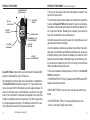
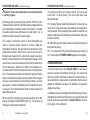
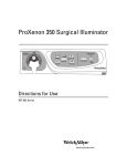
SENSIT® HXG-3
Combustible Gas Detector
INSTRUCTION MANUAL
Read and understand
instructions before use.
SSIFIE
LA
D
C
7WA6
Warning:
To prevent ignition
of flammable or
combustible
atmospheres,
disconnect power
before servicing.
For more information contact:
SENSIT TECHNOLOGIES
851 Transport Drive
Valparaiso, IN 46383
(888) 4-SENSIT
(473-6748)
Sensit® is a registered trademark of J And N
7-11 UL V4
Phone: (219) 465-2700
Fax: (219) 465-2701
www.gasleaksensors.com
P
V
SA E
OWE
A
R
Approved UL913, For Class 1,
Division 1, Groups C & D
hazardous locations when used
with alkaline batteries.
®
SENSIT HXG-3
C
B
M
ENU
CONTENTS
GENERAL DESCRIPTION
Page # 1.
2.
2.
3.
5.
5.
6.
7.
10.
11.
16.
18.
The Sensit® HXG-3 is designed to detect combustible gases. All
Sensit® HXG-3 instruments incorporate an advanced low power
semiconductor sensor to measure combustible gases in LEL (Lower
Explosive Limit) range. All measurements are in 0.1% LEL increments. The ppm display is simultaneously shown in 1 or 10ppm
increments (resolution). An automatically backlit display shows
all gas concentrations being measured. LEDs located on the front
of the instrument indicate preset visual warnings of increased gas
concentration.
Audible and visual alarms warn the operator of hazardous conditions being sensed. The preset alarms are indicated by a red flashing
LED, display indicator and alarm sound. The combustible gas
alarm is preset from 50% LEL (2.5% methane or 0.75% pentane).
Accessories and Parts
General Description
Specifications
Product Features
Sensor Type
Battery Installation
Adjustable Features - Factory Only
Operation and Use
Calibration Check
Menu
Calibration
Warranty and Repair Policy
ACCESSORIES AND PARTS
Standard Accessories (included)
Carrying Case
872-00001
Filter Cap
365-00045
Instruction Manual 750-00023
The Sensit® HXG-3 instrument is approved by Underwriters LaboWrist Strap
360-00040
Alkaline Batteries 310-00004
Optional Accessories and
Extension Adapter
Printer
PC Interface with Software
Parts
870-00012
870-00004
870-00008
Calibration Kit – Methane
Calibration Kit – Pentane
LEL Sensor
881-00015
881-00077
375-2611-01
NOTICE
CAUTION
This safety symbol is used to indicate a potentially hazardous situation
which, if not avoided, may result in minor or moderate injury.
1
ratories to UL913, for Class 1, Division 1, Groups C & D hazardous
locations when used with Duracell™ MN1400BK or equivalent alkaline batteries.
SPECIFICATIONS
TYPE
Leak
LEL
SENSOR SPECIFICATIONS
RESOLUTION
RANGE
1ppm or 10ppm
0-50,000ppm
0.1%
0-100%
ACCURACY
±10%
±10%
PRODUCT SPECIFICATIONS
Size:
11.5” x 3” x 2.32” (292 x 76 x 69 mm)
Weight:
1.2 lbs.
Operational Temp:
0 to 120° F
Storage Temp:
-20° to 132° F
Battery Life-Alkaline: approximately 25 hrs. continuous
2
PRODUCT FEATURES
PRODUCT FEATURES
IR COMMUNICATION
(DOWNLOADING)
P
®
SENSIT HXG-3
V
SA E
OWE
A
R
SPEAKER
(ON BACK)
The tick can be easily heard with the speaker located in the
back of the instrument.
SOLID STATE
SENSOR
BACKLIT
2 LINE DISPLAY
C
B
M
ENU
WARNING LED’S
THUMBWHEEL FOR
TICK ADJUSTMENT
PUSH PAD
BUTTONS
16” FLEXIBLE
GOOSENECK
continued from page 3
BATTERY
COMPARTMENT
The Infrared Communication window is located on the right side
to allow the Sensit® HXG-3 instrument to download: Calibration data; Communicate with Smart-Cal Calibration Station; PCi2s Computer Interface; Readings the operator has elected to
save to the instrument’s on-board memory.
A flexible gooseneck is used to assist in locating the source of
gas leaks and remote sampling.
A two line display continuously updates the operator of all available gas concentrations and alarms simultaneously as well as
indicates battery power. Below the display is a series of LEDs
that are preset to indicate combustible gas concentrations. During an alarm condition the red LED on the right side will flash
and an audible warning will sound.
Sensit® HXG-3 instruments are constructed of durable ABS
plastic to withstand the rigors of field use.
There are 3 operational button pads on the front of all Sensit®
HXG-3 instruments.
Incorporated in the hand grip area is the battery compartment.
All Sensit® HXG-3 instruments require 3 “C” type alkaline batteries. Duracell MN 1400 batteries provide approximately 25
hours of continuous use. A thumbwheel is located on the right
side of the instrument to activate the audible tick sound that
helps in locating the source of a gas leak. This tick is generated
by using specialized circuitry in combination with the LEL sensor located at the end of the gooseneck assembly.
• POWER/MUTE BUTTON (A): Operate the POWER and MUTE
feature and exit menu items.
3
(Continued on page 4)
• MENU BUTTON (B): Use to enter, change and select menu
items.
• SAVE/ZERO BUTTON (C): Use save data feature, zero
sensor, scroll and change menu items.
4
SENSOR TYPE
BATTERY INSTALLATION/REPLACEMENTContinued from pg 5
Combustible Gas Sensor
All Sensit® HXG-3 instruments incorporate a highly sensitive
semiconductor type sensor. The function and accuracy of the
sensor are monitored and controlled by specialized circuitry and
a microprocessor. This sensor is capable of measuring concentrations of 10ppm of methane (natural) gas up to 100% LEL.
If you do not use your right hand to hold the bottom of the battery compartment the batteries can come out. Observe the polarity markings on the inside of the battery holder. Improper installation will cause the instrument not to operate. Replace the
battery sleeve and allow the locking tab to snap into position.
BATTERY INSTALLATION/REPLACEMENT
CAUTION: Always change batteries in an environment
free of combustible gases.
Battery replacement is necessary when the display reads BAT
LOW, an audible alarm sounds and the green ready LED flashes.
When the instrument remains in BAT LOW, a countdown will
appear starting at 300 seconds (5 minutes) which is the maximum time remaining to shutdown.
Remove the battery sleeve cover by depressing the locking tab
on the front of the handle with a coin or flat object and pulling the
handle away from the top or display area of the instrument.
Place 3 approved batteries into the battery holder. For best results hold the battery compartment so that it lays in your right
hand. With your left hand install the battery that goes toward the
front first, the battery that is in contact with the rear spring second and finally insert the third battery in the center by forcing the
second battery such that the spring compresses and allows the
batteries to go into place.
5
(Continued on page 6)
NOTE: Improper battery installation will disable the instrument.
Check to be sure the handle is secure to the instrument body by
gently pulling the handle away. The handle will remain firmly in
place if a proper connection is made.
ADJUSTABLE FEATURES (FACTORY ONLY)
MENU ITEMS
Session Saves
RANGE
DEFAULT
1-100
6
0-100%
50%
1ppm or 10ppm
10ppm
30, 45, 60,
90, 180, 360
30 days
1-100
6
Warm-up Time
10-30 sec.
30 sec.
Purge Time
1-60 sec.
0 sec.
Alarm-LEL
PPM Display Option
Cal Due Interval
Show Session Log*
* Can be disabled
6
OPERATION AND USE
OPERATION AND USE continued from page 7
CAUTION: Always start any Sensit® HXG-3 in a gas
free environment to insure a proper zero.
4. Model 3.30 displays LEL% only. Model 3.35 displays LEL%
and ppm. All LEL readings have a resolution of 0.1% LEL or
50ppm methane. All ppm readings have a resolution of 1ppm or
10ppm and are displayed simultaneously with the LEL display.
1. Push and hold the power button (A) until the display illuminates.
2. If the display fails to illuminate or BAT LOW is shown on the
display replace the batteries. There is room in the carrying case
to keep an extra set of alkaline batteries.
3. During successful start-up the instrument will display:
a. Product name and model version
b. System check
c. Date and time
d. Gas Type
e. CAL PAST DUE when calibration is overdue
f. Warm-up countdown
g. AUTOZERO indicating the zeroing of the sensor
h. Working display
NOTE: If a sensor is completely inoperable or improperly zeroed
at start up, the display will show ERROR LEL followed by FAIL.
7
(Continued on page 8)
5. It may be necessary to manually zero the instrument based
on company practices and environmental conditions.
CAUTION: Zeroing should be done in a gas free environment only.
6. When testing high areas or overhead lines the use of the
optional extension adapter will allow a broom handle or painters
stick to extend the instrument to the area where sensing must
be accomplished. This slides onto the battery sleeve and is held
in place by the locking nut assembly.
7. When a gas is sensed the display will update. Additionally, a
series of LEDs on the front of the instrument will illuminate when
the preset concentrations of the calibration gas are reached. If
an alarm condition exists, based on a preset alarm point, the
red (HAZ 3) LED will flash and the alarm will sound.
The preset levels of the LED warning lights are:
Amber LED/Low 5 - 9.9% LEL methane
Red LED/Haz1 10.0 - 24.9% LEL
Red LED/Haz2 25.0 - 49.9% LEL
Red LED/Haz3 50.0 - 100% LEL
(continued on page 9)
8
OPERATION AND USE continued from page 8
OPERATION AND USE continued from page 9
Caution: These instruments have cross sensitivities to
a variety of gases.
The memory is factory set to store 6 events. This can be adjusted from 1-15 at the factory. The most recent save is first
during download.
8. During an alarm condition (factory default at 50% LEL) the
display will flash, LED HAZ 3 will flash and an audible alarm will
sound indicating a potentially unsafe environment. To disable
the audible alarm press and release the mute button (A). To
enable the alarm press and release it again.
9. To assist in locating the source of small combustible gas
leaks or surveying areas outdoors or indoors, rotate the
thumbwheel located on the right side of the instrument until a
steady ticking sound is heard. Note: There is no warm-up for
this feature as it uses the LEL sensor that is already operating.
Move the sensor toward the area suspected of leakage. As the
sensor moves closer to a leak source the tick will increase.When
the tick becomes a steady tone rotate the thumbwheel in a
clockwise direction while keeping the sensor in the same position. This will slow down the tick and allow the operator to find a
higher concentration using the same procedure.If the tick goes
away you have moved away from the leak or there is no more
gas present. For best results always use the leak detector prior
to using any liquid leak detection fluids as these sensors will
detect their presence.
10. At any time the operator may save the readings on the display by pressing the SAVE/ZERO button (C). This will save all
readings for download at a later time.
9
(Continued on page 10)
11. Following Federal, State, Municipal and/or Company procedures move to the areas where gas readings are suspected or
must be tested. During sampling the respective readings may
change. Audible and visual alarms will activate when the preset
limits are reached.
12. When being used in dark areas an automatic backlight will
illuminate the display.
13. To turn instrument off, push and hold the power button (A)
for 5-6 seconds until POWER DOWN appears on the display.
CALIBRATION CHECK
To verify the accuracy of any Sensit® HXG-3, it must be exposed to a known concentration of test gas. Any sensor that
does not meet the specifications listed in this manual may require calibration or replacement. A calibration check does not
update the calibration due date. Full calibration is required to
update these times.
A calibration past due message will illuminate during warm-up if
calibration has not been performed per your company specified
interval. Anytime it is suspected the Sensit® HXG-3 is not working properly, check calibration.
10
MENU
The Sensit® HXG-3 has several features in the user menu.
These include:
PRINT MENU: SESSION LOG - print data that was saved.
CAL LOG - print last 4 successful calibrations.
SMART CAL - access to Smart-Cal Calibration Station.
CALIBRATION: Calibrate LEL and access Smart-Cal
Calibration Station.
POWER OFF: Set the automatic shut off timer in minutes.
SET CLOCK: Set date and time.
SHOW CAL LOG: Display last calibration.
SHOW SES LOG: Display saved gas reading data with date
and time.
BUMP TEST: Perform automatic test for response to minimum
of 80% of calibrated gas value within 30 seconds.
SMART-CAL: Access automatic calibration station.
GAS TYPE: Select natural/methane or pentane as primary gas
to be sensed.
PRINT MENU
From the working display access the user menu by pressing
and holding the MENU button (B) until the top line of the display
reads USER MENU. The bottom line will read PRINT MENU.
Press the MENU button (B) to access the print menu options.
Use the SAVE/ZERO button (C) to select the CAL LOG or SESSION LOG.
At this time prepare the printer. Aim the IR window on the right
side of the instrument to the IR receptor on the printer. Position
the instrument 6-12” from the IR receptor and press the MENU
button (B). Downloading will begin immediately. When the display no longer reads PRINTING... use the SAVE/ZERO button
11
(Continued on page 12)
MENU continued from page 11
(C) to scroll to another PRINT MENU function. Pressing the
POWER/MUTE button (A) will reenter the USER MENU. Use
the SAVE/ZERO button (C) at this time to scroll to another
menu function. Pressing the POWER/MUTE button (A) will return the instrument to the working display.
CALIBRATION (see page 16 for complete instructions)
From the working display access the user menu by pressing
and holding the MENU button (B) until the top line of the display
reads USER MENU. Press and release the SAVE/ZERO button (C) until the bottom line displays CALIBRATION.
POWER OFF
From the working display access the menu by pressing and holding the MENU button (B) until the top line of the display reads
USER MENU. Press and release the SAVE/ZERO button (C) until
the bottom line displays POWER OFF. Press the MENU button
(B). Use the SAVE/ZERO button (C) to increase the number of
minutes of run time and the MENU button (B) to reduce them.
Setting the timer to 0 will cause the unit to always remain on. After
adjusting the number, press and release the left button (A) to save
the adjustment. Use the SAVE/ZERO button (C) at this time to
scroll to another menu function. Pressing the POWER/MUTE button (A) will return the instrument to the working display.
SET CLOCK
From the working display access the user menu by pressing
and holding the MENU button (B) until the top line of the display
reads USER MENU. Press and release the SAVE/ZERO button
(C) until the bottom line displays SET CLOCK. Press the MENU
button (B). The day will flash upon entering the SET CLOCK
(continued on page 13)
12
MENU
continued from page 12
option. The SAVE/ZERO button (C) advances to the next item
are based on US time and date settings using a 24 hour clock.
After adjusting all numbers press and release the POWER/
MUTE button (A) to save the adjustment. Use the SAVE/ZERO
button (C) at this time to scroll to another menu function in the
USER MENU. Pressing the POWER/MUTE button (A) will return the instrument to the working display.
SHOW CAL LOG
From the working display access the user menu by pressing
and holding the MENU button (B) until the top line of the display
reads USER MENU. Press and release the SAVE/ZERO button
(C) until the bottom line displays SHOW CAL LOG. Press the
MENU button (B) and the display will show the last gas calibrated and calibration date. Pressing any button will return the
display to the user menu. Pressing the POWER/MUTE button
(A) will return the instrument to the working display.
SHOW SES LOG
From the working display access the user menu by pressing
and holding the MENU button (B) until the top line of the display
reads USER MENU. Press and release the SAVE/ZERO button
(C) until the bottom line displays SHOW SES LOG. Press the
MENU button (B). Use the SAVE/ZERO button (C) to scroll to
the saved session you wish to review. SESSION 1 is the most
recent data saved. Pressing the MENU button (B) will display
the date and time of that session. Pressing the MENU button
(B) again will display the gas reading. Press the POWER/MUTE
13
(Continued on page 14)
MENU
continued from page 13
(B) again will display the gas reading. Press the POWER/MUTE
button (A) to return to SESSION(#) and pressing the SAVE/
ZERO button (C) will allow you to scroll all previously saved
SESSIONS. Pressing the POWER/MUTE button (A) 2 times
will return you to the USER MENU. Pressing the POWER/MUTE
button (A) once more returns you to the working display. The
number of stored session log saves is factory set at 6. It can
store up to 100 by changing a factory setting (contact SENSIT
TECHNOLOGIES for instructions).
BUMP TEST
From the working display access the menu by pressing and holding the MENU button (B) until the top line of the display reads
USER MENU. Press and release the SAVE/ZERO button (C) until
the bottom line displays BUMP TEST. Prepare 50% LEL methane
(or pentane) calibration gas for application to the instrument.
Apply calibration gas to the instrument sensor. Press the MENU
button (B). The reading must read 80% of calibrated value within
30 seconds. The reading is on the left side and the timer is on
the right side of the display.
If the instrument passes, the display will read BUMP TEST
PASSES, a beep will sound and the unit display will automatically return to the user menu. If the instrument fails, the display
will read BUMP TEST FAILED and a beep will sound. Repeated
bump test failure indicates possible need for instrument repair.
Contact J And N for instructions.
At the end of any bump test press the POWER/MUTE button
(A) to return to the working display.
(Continued on page 15)
14
MENU
continued from page 14
SMART-CAL (methane calibration only)
From the working display access the menu by pressing and
holding the MENU button (B) until the top line of the display
reads USER MENU. Press and release the SAVE/ZERO button
(C) until the bottom line displays SMART CAL. Place the
instrument into the cradle provided on the left side of the SmartCal Calibration Station. Attach the tubing from the station to the
instrument sensor. Press the MENU button (B). The display
will show SMART CAL Communicating. Select the test from
the Smart-Call Station to be performed. At the end of the test
the instrument will beep 3 times and display PASS or FAIL.
Retry the test if necessary by pressing the proper button on the
Smart-Cal Station again. Press and release the POWER/MUTE
button (A) to return the working display. Remove the tubing and
return instrument to service or send instrument to the proper
place for repair per company procedures.
SHORTCUT TO ACCESS SMART-CAL: Place the instrument
into the cradle provided on the left side of the Smart-Cal calibration Station. Attach the tubing from the station to the instrument sensor. While in the working display press the POWER/
MUTE button (A) for 2-3 seconds and release. The display will
show SMART CAL Communicating. Perform all tests as described in the SMART CAL section.
GAS TYPE
From the working display access the user menu by pressing
and holding the MENU button (B) until the top line of the display
15
(Continued on page 16)
GAS TYPE
continued from page 15
reads USER MENU. Press and release the SAVE/ZERO
BUTTON (C) until the bottom line displays GAS TYPE. Press the
MENU BUTTON (B). Press Button (B) or Button (C) to change
between PEN (Pentane) or NAT (Natural or Methane) as primary
gas to be sensed. Press Button (A) to confirm selection is made.
CALIBRATION
Calibration is the process of setting the readings of the instrument to equal the value of certified calibration gases.
NOTE: Using calibration kits other than recommended by
SENSIT TECHNOLOGIES may cause inaccurate readings.
Repairs are required if any sensor fails to calibrate. Consult SENSIT TECHNOLOGIES for details.
NOTE: When calibrating, the numbers shown on the display represent the numbers seen by the microprocessor
and should not be confused with actual gas readings.
Combustible Gas Calibration Procedure (50%LEL Methane
or 50%LEL Pentane)
The calibration gas used for this procedure should match the
Gas Type selected for your instrument. Refer to Gas Type in
the Menu section of this manual. Instruments set to methane
will calibrate with 50% LEL methane/air while those set to
pentane will calibrate with 50% LEL pentane/air.
Prior to calibration allow the instrument to operate for 5 minutes
in a gas free environment. Manually zero the instrument by
(continued on page 17)
16
CALIBRATION continued from page 16
WARRANTY AND REPAIR POLICY
press and holding the (C) button until the display shows
AUTOZERO. Prepare the corresponding calibration gas (methane
or pentane), regulator and adapter.
Your Sensit® HXG-3 is warranted to be free from defects in
materials and workmanship for a period of two years after purchase (excluding sensor, calibration and batteries). If within the
warranty period, your instrument should become inoperative from
such defects, the unit will be repaired or replaced at our option.
This warranty covers normal use and does not cover damage
which occurs in shipment or failure which results from alteration,
tampering, accident, misuse, abuse, neglect or improper maintenance. Proof of purchase may be required before warranty is
rendered. Units out of warranty will be repaired for a service
charge. Internal repair or maintenance must be completed by a
SENSIT TECHNOLOGIES authorized technician. Violation will
void warranty. Units must be returned postpaid, insured and to
the attention of the Service Dept. for warranty or repair.
From the working display access the USER MENU by pressing
and holding the (B) button until the top line of the display reads
USER MENU. Press and release the (C) button and the bottom
line should read CALIBRATION. Press and release the (B) button,
the top line will read CALIBRATION and the bottom line will read
LEL 50%.
Apply the appropriate calibration gas for your instruments set-up
and press the (B) button to start the automated calibration process.
If calibration is successful, the display will flash DATA SAVED
before automatically returning to the calibration menu. Pressing
the (A) button repeatedly will return the instrument to the working
display. Remember to disconnect and shut off the gas supply.
If calibration is unsuccessful, the display will flash BAD CAL before
returning to the calibration menu. In the event of a BAD CAL,
remove the instrument from service and contact SENSIT
Technologies for assistance.
NOTE: Calibration will be based on the last successful calibration.
The calibration due date will not be updated until successful
calibration has occurred. Any instrument that does not calibrate
This warranty gives you specific legal rights and you may have
other rights which vary from state to state.
SENSIT TECHNOLOGIES
ATTN: Service Dept.
851 Transport Drive
Valparaiso, IN 46383
(888) 4-SENSIT
(473-6748)
Phone: (219) 465-2700
Fax: (219) 465-2701
www.gasleaksensors.com
requires service. Contact SENSIT TECHNOLOGIES for details.
17
18