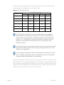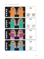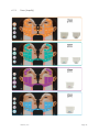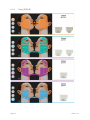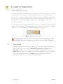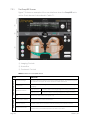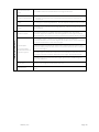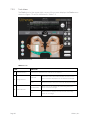
1
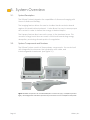
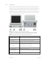
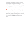
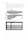
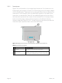
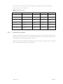
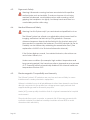
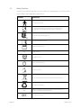
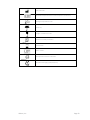
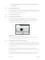
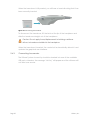
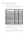
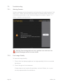
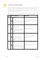
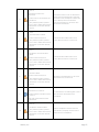
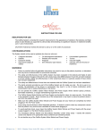
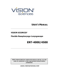
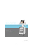
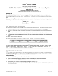
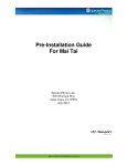
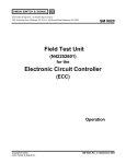
Ulthera® System
Instructions for Use
Featuring DeepSEE® Technology for Ultherapy®
THIS PAGE INTENTIONALLY LEFT BLANK
Page 2
Ulthera, Inc.
March 2015
Published in the USA
CAUTION: UNITED STATES FEDERAL LAW RESTRICTS THIS DEVICE TO SALE
BY OR ON THE ORDER OF A PHYSICIAN.
THE ULTHERA® SYSTEM IS INTENDED FOR USE ONLY BY PROPERLY
TRAINED PHYSICIANS AND PROPERLY TRAINED PERSONS UNDER THE
SUPERVISION OF SUCH A TRAINED PHYSICIAN (HENCEFORTH “THE USER”).
PRIOR TO OPERATING THE SYSTEM, THE USER MUST THOROUGHLY READ
AND UNDERSTAND THIS MANUAL. IMPROPER USE OF THE SYSTEM MAY
CAUSE PERSONAL INJURY AND/OR DAMAGE TO THE SYSTEM THAT MAY
INVALIDATE THE WARRANTY AGREEMENT.
THE ULTHERA® SYSTEM IS INTENDED FOR LIFTING AND SCULPTING OF SKIN BY
WAY OF DEPOSITION OF MICRO-FOCUSED ULTRASOUND ENERGY AT DEPTHS
BETWEEN 1.5 AND 4.5MM BENEATH THE SKIN. DEPOSITION OF ENERGY RESULTS
IN A CHANGE TO THE PHYSIOLOGY RESULTING IN STIMULATION OF NEW
COLLAGEN AND ELASTIN AS PART OF THE HEALING PROCESS.
THE ULTHERA TRANSDUCERS CAN BE REUSED UNTIL 2400 LINES OF TREATMENT IS
PROVIDED.
THE USEFUL LIFE OF THE ULTHERA CONTROL UNIT IS 4 YEARS AND
HANDPIECE 5 YEARS BASED ON THE USEFUL LIFE OF THE COMPONENTS
AND TESTING. THIS STATEMENT DOES NOT IMPLY A WARRNTY COVERING
THAT PERIOD OF TIME. PLEASE SEE WARRANTY INFORMATION IN YOUR
PURCHASE TERMS AND CONDITIONS.
Ulthera, Inc.
Page 3
© 2015, Ulthera, Inc. All Rights Reserved. The marks ULTHERA, ULTHERAPY, and DEEPSEE
are registered in the U.S. and/or certain foreign countries to Ulthera, Inc. (henceforth
"Ulthera"). The marks SEE THE POWER OF SOUND, SEE THE BEAUTY OF SOUND, ULTHERA
AMPLIFY, ULTHERAPY AMPLIFY, and AMPLIFY are trademarks of Ulthera.
This manual may not be copied, translated, or reproduced in whole or in part without
the express written consent of Ulthera.
Various features of the Ulthera® System are covered by U.S. Patents 6,049,159,
7,758,524, 8,366,622, 8,444,562, 8,506,486, 8,535,228, 8,641,622, 8,690,778, 8,690,779,
8,690,780, and 8,915,853 and contemplated features may be covered by one or more
of the following U.S. Patents: 5,820,564; 6,036,646; 6,050,943; 6,120,452; 6,213,948;
6,440,071; 6,500,121; 6,540,679; 7,142,905; 7,229,411; 7,393,325; 7,491,171; 7,530,958;
7,571,336; 7,615,016; 7,824,348; 7,914,453; 8,057,389; 8,066,641; 8,166,332; 8,128,618;
8,133,180; 8,235,909; 8,282,554; 8,333,700; 8,409,097; 8,460,193; 8,480,585; 8,523,775;
8,636,665; 8,663,112; 8,672,848; 8,708,935; 8,715,186; 8,857,438; 8,915,870; 8,915,854; and
8,920,324.
More than 100 other U.S. and International patents to which Ulthera has
rights are issued, published, or pending.
Page 4
Ulthera, Inc.
THIS PAGE INTENTIONALLY LEFT BLANK
Ulthera, Inc.
Page 5
Table of Contents
1.
2.
3.
4.
5.
6.
Introduction to Manual ......................................................................................... 8
1.1.
Purpose .................................................................................................................. 8
1.2.
Conventions .......................................................................................................... 8
Medical Safety ....................................................................................................... 9
2.1.
Intended Use ......................................................................................................... 9
2.2.
Indications for Use ................................................................................................ 9
2.3.
Contraindications ................................................................................................. 9
2.4.
Precautions ............................................................................................................ 9
2.5.
Patient Safety ...................................................................................................... 10
2.6.
Potential Side Effects .......................................................................................... 11
2.7.
Complaints and Adverse Events ...................................................................... 11
System Overview .................................................................................................. 12
3.1.
System Description ............................................................................................. 12
3.2.
System Components and Features.................................................................. 12
System Safety........................................................................................................ 18
4.1.
Electrical and Fire Safety ................................................................................... 18
4.2.
Equipment Use and Care .................................................................................. 19
4.3.
Ergonomic Safety ............................................................................................... 20
4.4.
Medical Ultrasound Safety ................................................................................ 20
4.5.
Electromagnetic Compatibility and Immunity ............................................... 20
4.6.
Disposal ................................................................................................................ 21
4.7.
Safety Symbols .................................................................................................... 22
Setting Up for First-Time Use ................................................................................ 24
5.1.
Unpacking ........................................................................................................... 24
5.2.
Physical Environment ......................................................................................... 24
5.3.
Electrical Requirements ..................................................................................... 25
5.4.
Connecting Components ................................................................................. 25
Treatment Guidelines .......................................................................................... 27
6.1.
7.
System Operation ................................................................................................ 37
7.1.
Page 6
Preset Guidelines and Energy Levels ............................................................... 27
Ulthera System Access Key ............................................................................... 37
Ulthera, Inc.
7.2.
User Interface ...................................................................................................... 37
7.3.
Operating Instructions ........................................................................................ 43
7.4.
Adjunctive Functions.......................................................................................... 50
7.5.
Troubleshooting .................................................................................................. 54
8.
System Messages ................................................................................................. 56
9.
Cleaning and Care ............................................................................................. 60
9.1.
Cleaning the Transducer and Handpiece ..................................................... 60
9.2.
General Care of the System ............................................................................. 60
10.
Reorder Information ............................................................................................ 62
11.
Safety Standards and Regulatory Classifications ........................................... 63
Ulthera, Inc.
Page 7
1. Introduction to Manual
1.1.
Purpose
This Instructions for Use manual provides a description of the System
components, its controls and displays, instructions for its operation, and other
equipment information important to the user.
Warning: Do NOT operate the Ulthera System before reading this
manual thoroughly. In addition to this manual, additional clinical
training may be available by the Company or your local distributor. For
more information on training available, please contact your local
representative.
1.2.
Conventions
Note: Notes designate information of special interest.
Caution: Cautions alert the user to precautionary steps necessary to
properly operate the system. Failure to observe these cautions may void
the warranty.
Warning: Warnings alert the user to information that is of the highest
importance and vital to the safety of the patient and user.
All procedures are broken down by numbered steps. Steps must be
completed in the sequence they are presented.
Bulleted lists indicate general information about a particular function or
procedure. They do not imply a sequential procedure.
Control names are spelled as they are on the system, and they appear in
Bold text.
Page 8
Ulthera, Inc.
2. Medical Safety
2.1.
Intended Use
The Ulthera® System is intended for lifting and sculpting of skin by way of the
deposition of micro-focused ultrasound energy at depths between 1.5 mm and
4.5 mm beneath the skin. Deposition of ultrasound energy results in a change to
the physiology, resulting in stimulation of new collagen and elastin as part of the
healing process.
The Ulthera System is also intended for the treatment of Axillary Hyperhidrosis by
way of the deposition of the micro-focused ultrasound energy at depths
between 3.0 mm and 4.5 mm beneath the skin, targeting the depth at which
sweat glands reside. Coagulation takes place in tissue located at the dermal
hypodermal interface where the sweat glands reside using a surface contact
applicator. Sweat glands are destroyed during coagulation.
2.2.
Indications for Use
The Ulthera System is indicated for:
•
•
2.3.
Use for non-invasive dermatological sculpting and lifting of the dermis
o Upper Face
o Lower Face
o Neck
o Décolleté
Non-invasive treatment of Axillary Hyperhidrosis
Contraindications
The Ulthera System is contraindicated for use in patients with:
•
•
•
2.4.
Open wounds or lesions on the face and/or neck
Severe or cystic acne on the face and/or neck
Pacemakers and electronic device implants in treated area
Precautions
When not in use by trained personnel, the Ulthera System Access Key should be
removed from the system to help prevent unauthorized use. Keep the Ulthera
System Access Key in a designated place accessible only to authorized and
trained personnel.
Ulthera, Inc.
Page 9
The Ulthera System has not been evaluated for use over various materials.
Therefore, treatment is not recommended directly over those areas with any
of the following:
•
•
•
•
•
Mechanical implants
Dermal fillers
Implanted electrical devices in the face and/or neck
Metal stents in the area of treatment (e.g. face, neck, décolleté (center
of chest))
Breast implants
Treatment energy is not recommended for use directly on an existing keloid.
The Ulthera System has not been evaluated for use in patients on an
anticoagulant treatment plan.
It is recommended that the following areas should be avoided during
treatment:
•
•
•
Thyroid gland, thyroid cartilage and trachea
Major vessels
Breast tissue or breast implant
The Ulthera System has not been evaluated for use in the following patient
populations:
•
•
•
2.5.
Pregnant or breast-feeding women
Children
Those with the following disease states:
o A hemorrhagic disorder or hemostatic dysfunction
o An active systemic or local skin disease that may alter wound
healing
o Herpes simplex
o Autoimmune disease
o Diabetes
o Epilepsy
o Bell’s palsy
Patient Safety
Warning: Ulthera should not be used on a patient’s eyes or in a location or
technique where ultrasound energy can reach the eye.
Warning: Use this system only if you are trained and qualified to do so.
Warning: If any problems occur during system operation, take immediate
action(s): lift the transducer off the patient’s skin, press the See pushbutton
Page 10
Ulthera, Inc.
on the handle to discontinue the treatment in progress, and/or press the
red emergency Stop button to completely halt system operation.
2.6.
Potential Side Effects
Side effects reported in the clinical evaluation of the Ulthera System were mild
and transient in nature. These were limited to:
•
•
•
•
•
•
2.7.
Erythema (redness): The treated area may exhibit erythema immediately
following treatment. This typically resolves within a few hours of treatment.
Edema (swelling): The treated area may exhibit mild edema following
treatment. This typically resolves within a few days of treatment.
Pain: Momentary discomfort may be experienced during the procedure
while energy is being deposited. Post-procedure discomfort or tenderness to
the touch is also possible.
Bruising: Mild bruising, which is caused by damage to soft tissue blood
vessels, may occur occasionally and typically resolves within a few days of
treatment.
Nerve effects:
o Transient local muscle weakness may result after treatment due to
inflammation of a motor nerve.
o Transient numbness may result after treatment due to inflammation of
a sensory nerve.
o Transient pain, paresthesia and/or tingling may be experienced.
o No permanent injuries to facial nerves have been reported.
Scarring: The possibility for scar formation (which may respond to medical
care) may exist if incorrect treatment technique is used.
Complaints and Adverse Events
No serious adverse events were observed during the clinical study evaluation of
the Ulthera System.
Ulthera follows MDR (Medical Device Reporting) rules for handling complaints
and adverse events. Should an adverse event be suspected or reported,
contact Ulthera, Inc. at the number on the back page of this document. For
those outside the U.S., contact your local Ulthera representative.
Ulthera, Inc.
Page 11
3. System Overview
3.1.
System Description
The Ulthera System integrates the capabilities of ultrasound imaging with
those of ultrasound therapy.
The imaging feature allows the user to visualize the skin and sub-dermal
regions of interest before treatment. It also allows the user to assure proper
skin contact in order to deliver the energy at desired depths.
The therapy feature directs acoustic waves to the treatment area. This
acoustic energy heats tissue as a result of frictional losses during energy
absorption, producing discrete points of coagulation.
3.2.
System Components and Features
The Ulthera System consists of three primary components: the control unit
with integrated touchscreen, the handpiece with cable, and
interchangeable transducers (see Figure 3.1).
Figure 3.1 Main components of the Ulthera® System: control unit (top), handpiece (bottom
right), and image/treat transducer (bottom left) that inserts into the handpiece receptacle
Page 12
Ulthera, Inc.
3.2.1.
Control Unit
The control unit is the tabletop information center for the Ulthera System. It
houses the touchscreen monitor and Graphical User Interface (GUI) that
allows the user to interact with the device. This screen sets and displays the
operating conditions, including equipment activation status, treatment
parameters, system messages and prompts, and ultrasound images. Figure
3.2 illustrates the physical features of the control unit, such as the various
connector ports and power controls.
Figure 3.2 Control Unit Front View (left) and Rear View (right)
See Table 3.1 for a description of the controls and connector ports of the control unit.
Table 3.1 Control Unit Connector Ports and Controls (See Figure 3.2)
ITEM
Handpiece Connector
DESCRIPTION
1 Receptacle
Socket for plugging in handpiece cable
2 USB Ports (two)
For optional USB removable storage device
3 Emergency Stop
Halts system operation if pressed
• Momentarily press to turn system ON
4 On / Off Button
• Momentarily press to turn system OFF
• Press and hold to force system shutdown
5 Rear Panel USB port
For Ulthera System Access Key
6 Main Power Switch
Supplies power to system. Leave ON (symbol “|” pressed in).
7 Power Cord Receptacle
Socket for attachment of power cord
Ulthera, Inc.
Page 13
Below the monitor, on the front panel of the control unit, is a handpiece
connector receptacle that interfaces with the handpiece cable. On the
front right of the panel is an On/Off button and an emergency Stop button.
When turned OFF via the On/Off button, the system goes into a very low
power standby mode unless the Main Power Switch is also turned to the OFF
position by pressing the ‘O’ symbol. The front of the control unit also has two
Universal Serial Bus (USB) ports: both ports may be used for the Ulthera System
Access Key or for an optional removable storage device (“thumb drive”).
Warning: When not in use by trained personnel, the Ulthera System
Access Key should be removed from the system to help prevent
unauthorized use. Keep the Ulthera System Access Key in a designated
place accessible only to authorized and trained personnel.
The rear of the control unit has a USB port, an AC power receptacle and the
main power switch. The main power switch should be left in the powered
position (with the “|” pressed inward). In such a configuration, the control
unit may be turned ON via the front panel On/Off button and can be turned
OFF via either the front panel On/Off button or via the graphical user
interface.
Page 14
Ulthera, Inc.
3.2.2.
Handpiece
The handpiece is a handle with an integrated receptacle for insertion of a
transducer on one end and an electrical cable for attachment to the control
system on the other end. The handpiece has two types of buttons: one to
image (SEE) and the other to deliver therapy (TREAT). Figure 3.3 provides two
views of the handpiece, including one showing it connected to an
Image/Treat transducer. Table 3.2 is a description of the various components
and features illustrated in Figure 3.3.
Figure 3.3 Handpiece with Transducer Inserted (top and side views)
Table 3.2 Handpiece and Transducer Description
ITEM
DESCRIPTION
• Engages IMAGING state (if not already imaging)
1 SEE Pushbutton
• Places system in READY state (Times out in 40 seconds)
• Stops TREATING if treatment is in progress
2 TREAT Pushbuttons
Engages TREATING state
3 Latch
Locks transducer into handpiece
4 Transducer
Image/treat transducer
5 Strain Relief / Cable Connects handpiece to control unit
Ulthera, Inc.
Page 15
3.2.3.
Transducers
Figure 3.4 is an illustration of an image/treat transducer. The transducer can
image and treat a region of tissue up to 25 mm long and can image a depth
of up to 8 millimeters. Treatment occurs along a line less than or equal to the
transducer’s active length, which is indicated by guides on the sides of the
transducer, as described in Table 3.3. An additional guide at the front tip of
the transducer represents the center of the treatment line. In therapy mode,
bursts of sound energy create a linear sequence of individual, discrete,
thermal coagulation points (TCPs). A label atop the transducer provides the
transducer type, expiration date, and other information.
Figure 3.4 Image/Treat Transducer, Separated from Handpiece (see Table 3.3)
Table 3.3 Transducer Description
ITEM
Page 16
DESCRIPTION
1 Labeling
Transducer type and other information
2 Treat Guides
Markers denoting maximum treatment line length
and center of treatment line (center of transducer)
Ulthera, Inc.
The types of transducers reflect variations in frequencies and treatment
depths as shown in Table 3.4.
Table 3.4 Transducer Types
3.2.4.
TRANSDUCER TYPE
TREAT FREQUENCY
TREAT DEPTH
IMAGE DEPTH
SCAN LENGTH
DS 7 – 3.0
7 MHz
3.0 mm
0 − 8 mm
25 mm
DS 7 – 3.0N
7 MHz
3.0 mm
0 – 8 mm
14 mm
DS 4 – 4.5
4 MHz
4.5 mm
0 − 8 mm
25 mm
DS 7 – 4.5
7 MHz
4.5 mm
0 − 8 mm
25 mm
DS 10 – 1.5
10 MHz
1.5 mm
0 − 8 mm
25 mm
DS 10 – 1.5N
10 MHz
1.5 mm
0 − 8 mm
14 mm
Essential Accessories
Other essential components provided for operation of the Ulthera System are
the power cord that connects the Ulthera System to an AC power outlet, and
the proprietary Ulthera System Access Key.
Ultrasound gel to facilitate transmission of the acoustic energy is also required,
but is not provided as part of the System.
Ulthera, Inc.
Page 17
4. System Safety
The following precautions and warnings must be reviewed and observed:
4.1.
Electrical and Fire Safety
Warning: To avoid risk of electric shock, always inspect the Ulthera
transducer, handpiece and cable before use. Do not use a damaged
cable or a transducer that has been damaged or is leaking fluid.
The Ulthera System is intended for indoor, dry location use. Avoid liquid
spills and splashes. Keep coupling gel away from the handpiecetransducer connections.
The Ulthera System comes with a three-conductor AC power cord and
plug. Use a properly grounded outlet and always plug the Ulthera
System directly into the outlet. Never remove the ground conductor or
compromise the ground conductor via any AC adapter plugs or
extension cords.
Disconnect the power cord from the outlet by pulling on the plug and
not the cord.
AC powered USB printers or storage devices may pose a shock hazard.
Do not touch the USB connectors and the patient at the same time.
Turn off the AC power switch and disconnect the AC power supply
before cleaning the control unit.
Do not remove the covers on the control unit or handpiece; the control
unit contains hazardous voltages. The Ulthera System contains no userserviceable components. If the System requires service, contact Ulthera,
Inc.
No modification of this equipment is allowed.
The Ulthera System should not be used near flammable gases or
anesthetics. Fire or explosion can result. The Ulthera System is not AP or
APG rated.
Page 18
Ulthera, Inc.
Avoid restricting ventilation under and behind the Ulthera control unit.
Maintain an open space of at least 4 inches/ 10 cm around the control
unit. If ventilation holes are obstructed, the System could overheat.
The Ulthera control unit is rated as a Type B patient applied part. It may
provide a connection between the patient and protective earth. This
may present a hazard if the patient becomes connected to other
equipment with excessive electrical current leakage.
Do not touch the handpiece electrical contacts and patient
simultaneously.
To avoid a burn hazard, remove the transducer from the patient before
performing HF electrosurgical procedures.
4.2.
Equipment Use and Care
Caution: Failure to observe these precautions may void the warranty.
The Ulthera handpiece connectors must be kept clean and dry. Do not
use the transducer if the connectors have been immersed in liquid. See
the instructions for cleaning the transducer.
Every effort has been made to make the transducers as rugged as
possible; however, they may become permanently damaged if
dropped onto a hard surface or if the membrane is punctured.
Transducers damaged in this manner are not covered by the warranty.
The Ulthera System has no user-serviceable components. Do not
attempt to open the control unit enclosure or transducers. Contact
Ulthera, Inc. if service is required.
When not in use by trained personnel, the Ulthera System Access Key
should be removed from the System to help prevent unauthorized use.
Keep the Ulthera System Access Key in a designated place accessible
only to authorized and trained personnel.
Ulthera, Inc.
Page 19
4.3.
Ergonomic Safety
Warning: Ultrasound scanning has been associated with repetitive
motion injuries such as tendinitis. To reduce chances of such injury,
maintain a balanced, comfortable posture while scanning, avoid
gripping the handpiece too tightly, and keep hands and arms in a
comfortable position while using.
4.4.
Medical Ultrasound Safety
Warning: Use this System only if you are trained and qualified to do so.
The Ulthera System has a fixed, non-adjustable output power level for
imaging, well below the limits set by FDA guidelines. However,
ultrasound exposure times should be limited to the shortest amount of
time needed to complete the treatment. The AFAP principle (As Far As
Possible) can be followed by minimizing the examination time. (See
explanation of AFAP in the Technical Information Manual).
If the System displays unusual / inconsistent behavior, discontinue use
and contact Ulthera, Inc.
Under some conditions (for example, high ambient temperature and
long scanning period), the transducer surface temperature may exceed
41oC. Scanning will be automatically disabled if the internal transducer
temperature reaches 43oC.
4.5.
Electromagnetic Compatibility and Immunity
The Ulthera System’s RF emissions are very low and are not likely to cause
interference in nearby electronic equipment.
Ulthera is suitable for use in all establishments other than domestic and those
directly connected to the public low voltage power supply network that
supplies buildings used for domestic purposes.
Mains (AC) power quality should be that of a typical commercial or hospital
environment.
Floors should be wood, concrete, or ceramic tile. If floors are covered with
synthetic material, the relative humidity should be at least 30% to avoid
excessive static electricity.
Page 20
Ulthera, Inc.
Warning: The Ulthera System should not be situated adjacent to, or
stacked with, other electronic equipment. If the System must be installed
in close proximity to other equipment, both the Ulthera System and the
nearby equipment should be observed to verify normal operation in that
configuration.
Caution: EMI (Electro-Magnetic Interference) from other electronic
systems may cause degradation of the ultrasound image. Ulthera has
been designed to meet the standards of IEC60601-1-2 for
electromagnetic compatibility; however, some computer equipment
unintentionally emits strong interfering RF signals. Portable RF
communication devices may also affect Ulthera. If image quality is
degraded by EMI, the System may need to be relocated or
reconfigured.
Warning: Use of accessories (other than those specified) may result in
increased emissions, or decreased immunity of this System.
4.6.
Disposal
Depleted transducers should be disposed of in accordance with federal,
state, and local regulations.
Ulthera, Inc.
Page 21
4.7.
Safety Symbols
A variety of symbols appear on the transducer, handpiece, or control unit in
accordance with regulatory guidance.
SYMBOL
DEFINITION
Type B Applied Part
CE marking indicating manufacturer’s declaration of
compliance with appropriate EU product directives
Canadian Standards Agency
Consult instructions for use
Date of Manufacture
SN
Serial Number
Emergency Stop
Power Standby Switch
Indoor Use Only
Keep electrical waste separate from municipal waste
Recycle Packaging
IPx1
Mated handpiece and transducer protected from the
effects of vertically dripping water
Catalogue Number
Page 22
Ulthera, Inc.
Manufacturer
Authorized representative in the European Community
Storage Temperature Limit
Keep Dry
Fragile, handle with care
Relative Humidity Limitation
Use-By Date
Batch Code
Atmospheric Pressure Limitation
Recycle Packaging (Polyethylene)
Ulthera, Inc.
Page 23
5. Setting Up for First-Time Use
5.1.
Unpacking
The control unit and handpiece are shipped together in one container.
Transducers are packaged and shipped separately from the control unit and
handpiece, in ready-to-use, non-sterile pouches.
5.2.
Physical Environment
5.2.1.
System Base
The System may be placed on a cart or counter with the depth to
accommodate the control unit, handpiece, and power cord provided. A
cart is recommended to offer maximum mobility for the user when treating
the patient and provide a more secure housing for the handpiece. System
weight and dimensions are listed in the Technical Information Manual –
Ulthera System Specifications.
Space should be provided around the back, sides, bottom and top of the
System for cooling. During continuous use for extended periods of time, it is
normal for the System to be warm.
5.2.2.
Electromagnetic Environment (See the detailed EMC Guidance in
Section 3 of the Technical Information Manual)
The System is not likely to cause interference in nearby electronic equipment;
however, other electronic equipment should not be stacked or placed
immediately adjacent to the System.
Flooring should be wood, concrete, or ceramic tile. If covered with synthetic
material, the relative humidity should be at least 30%.
Warning: The Ulthera System should not be situated adjacent to, or
stacked with, other electronic equipment. If the System must be installed
in close proximity to other equipment, both the Ulthera System and the
nearby equipment should be observed to verify normal operation in that
configuration.
Caution: EMI (Electro-Magnetic Interference) from other electronic
systems may cause degradation of the ultrasound image. The Ulthera
System has been designed to meet the standards of IEC60601-1-2 for
electromagnetic compatibility; however, some computer equipment
unintentionally emits strong interfering RF signals. Portable RF
communication devices may also affect the Ulthera System. If image
Page 24
Ulthera, Inc.
quality is degraded by EMI, the System may need to be relocated or
reconfigured.
5.3.
Electrical Requirements
The Ulthera System has an international power supply standards and may be
used with 100-240 VAC, 50-60 Hz power systems. See Section 4.1 Electrical
and Fire Safety for additional information.
5.4.
Connecting Components
5.4.1.
Connecting the Handpiece
The handpiece connector receptacle is located on the left side of the
control unit’s front panel as shown in Figure 5.1. To attach the handpiece
connector, align it with the white dot facing up and push it into the
receptacle. It will latch when seated properly.
Figure 5.1 Handpiece Connector Receptacle
To disconnect the handpiece, twist the coupling ring on the connector
counterclockwise while pulling outwards.
5.4.2.
Identifying and Connecting Transducers
Transducers are identified by the label on the top of the transducer, which
includes the name of the transducer (Ulthera DeepSEE), treatment frequency
and treatment depth (DS X-X), a unique serial number, a part number, and
date of manufacture.
The Treatment Guidelines on the control unit interface will display the
recommended transducer to utilize based on the anatomical area you have
selected to treat.
Remove the transducer indicated from its protective pouch. To connect the
transducer, slide the transducer into the handpiece as shown in Figure 5.2.
Ulthera, Inc.
Page 25
When the transducer is fully seated, you will hear a tone indicating that it has
been correctly inserted.
Figure 5.2 Connecting a Transducer
To disconnect the transducer, lift the latch at the tip of the handpiece and
slide the transducer straight out of the handpiece.
Caution: Do not apply force/displacement to latching cantilever
without a transducer installed in the handpiece.
When the transducer is inserted, the control unit automatically detects it and
updates the graphical user interface.
5.4.3.
Connecting Accessories
The Ulthera System Access Key should be inserted into one of the available
USB ports; otherwise, the message “No Key” will appear and the software will
not allow user access.
Page 26
Ulthera, Inc.
6. Treatment Guidelines
6.1.
Preset Guidelines and Energy Levels
The Ulthera System is programmed with preset guidelines that have been
established through clinical experience, studies and/or literature. Table
6.1describes the preset guidelines available on your System.
Table 6.1 Guideline Names and Energy Levels
Energy Level
Range
Default
Energy Level
Face & Neck (Amplify)
1–4
2
Face & Neck (5.0 PLUS)
1–4
2
Face (Amplify)
1–4
2
Face (5.0 PLUS)
1–4
2
Chest
1–4
4
Hyperhidrosis
1–4
4
General Regions (Face & Neck)
1–4
2
Train: Face & Neck (Amplify)
0 only
0
Train: Face & Neck (5.0 PLUS)
0 only
0
Train: Face (Amplify)
0 only
0
Train: Face (5.0 PLUS)
0 only
0
Train: Chest
0 only
0
Train: Hyperhidrosis
0 only
0
Guideline Name
To facilitate training with your System, specific training guidelines have been
pre-programmed into the guideline list as well. These are noted as “Train: ...”
These training guidelines should be used for training purposes only where no
energy delivery is desired. Lines available for the transducer will not be
decremented while in a training guideline.
If regions other than those depicted in the preset guidelines are desired, it is
recommended that you utilize the User Regions function as described in
section 7.2.3. This function will allow you to define text-based regions for you
to select and treat against.
Ulthera, Inc.
Page 27
Each transducer is programmed with set energy levels. Table 6.2 describes
the energy levels available for each transducer.
Table 6.2 Transducer Energy Levels
TRANSDUCER
LEVEL 4
ENERGY LEVELS [J]
LEVEL 3 LEVEL 2 LEVEL 1
LEVEL 0
DS 4 - 4.5
1.20
1.00
0.90
0.75
0.00
DS 7-4.5
1.05
0.90
0.75
0.66
0.00
DS 7 - 3.0
0.45
0.35
0.30
0.25
0.00
DS 7 - 3.0N
0.45
0.35
0.30
0.25
0.00
DS 10-1.5
0.25
0.20
0.18
0.15
0.00
DS 10-1.5N
0.25
0.20
0.18
0.15
0.00
Note: Energy level defaults may vary depending on the guidelines
selected prior to performing a treatment. The user has the ability to
adjust these energy settings by using the Energy control described in
section 7.2.1. If adjusted, the System will retain the setting across all
regions for that particular transducer and for the duration of the
treatment session.
Note: Removing and re-inserting a transducer within a treatment session
will put the transducer back to the energy setting used last, not to the
default for the guideline.
Note: Ending the treatment session and starting a new session with the
same or different guideline will put all transducers back to the default
energy settings as prescribed by the guideline.
The preset guidelines as they appear on the System for each transducer type
are listed below. The recommended line count for each region is depicted by
the numerical value displayed. Regions shown without a numerical value are
regions that are available for the treating clinician to select and treat at their
discretion, but a specific line count is not directed.
Page 28
Ulthera, Inc.
6.1.1.
Face & Neck (Amplify)
Ulthera, Inc.
Page 29
6.1.2.
Page 30
Face & Neck (5.0PLUS)
Ulthera, Inc.
6.1.3.
Face (Amplify)
Ulthera, Inc.
Page 31
6.1.4.
Page 32
Face (5.0PLUS)
Ulthera, Inc.
6.1.5.
Chest
Ulthera, Inc.
Page 33
6.1.6.
Page 34
Hyperhidrosis
Ulthera, Inc.
6.1.7.
Hyperhidrosis
Note: The Ulthera System is not indicated for treating hyperhidrosis
related to other body areas or generalized hyperhidrosis.
6.1.7.1.
Delivery of Focused Ultrasound Energy to the Axilla
Caution: Prior to delivery of focused ultrasound to patient, wipe all
patient contact surfaces with a CaviCide™ wipe and allow to dry. Wipe
patient contact surfaces once more with isopropyl alcohol, then
proceed.
Note: Please note that in clinical studies, localized, sub-dermal injections
of lidocaine with epinephrine were used to anesthetize the axillae of
patients prior to Ultherapy treatment.
Using the treatment grid (Section 6.1.6.), sequentially place lines of focused
ultrasound energy to the axilla in groups of 10 lines per square using the DS 44.5 for two passes, followed by DS 7-3.0 for two passes, for a total of 480 lines
per axilla. Proceed to the contralateral axilla and repeat the delivery of
focused ultrasound energy.
Ulthera, Inc.
Page 35
6.1.8.
Page 36
General Regions (Face & Neck)
Ulthera, Inc.
7. System Operation
7.1.
Ulthera System Access Key
Your Ulthera System is equipped with a unique Access Key that gives you access
to Ultherapy on your System. You should keep this key in a safe and secure
location that is only accessible to authorized personnel. In addition to providing
you secure access to your System, the Access Key also functions as a USB
storage device for transferring information from your Ulthera System to an
external computer.
To use your Access Key simply insert it into one of the available USB ports. During
regular use it is highly recommended that you insert the Access Key into the rear
USB port so it is not bumped or damaged during continual use.
Figure 7.1 Ulthera System Access Key
Warning: Do NOT format your Ulthera System Access Key. Doing so could
deactivate your key causing you to lose access to your Ulthera System.
7.2.
User Interface
The main screen on the Ulthera System monitor has three tabs located in the
upper right corner of the screen: DeepSEE, Patient Info, and Setup. The
DeepSEE tab displays the controls for imaging and treating soft tissue. The
Patient Info tab displays information and tools for beginning a treatment and
setting up a patient record. The Setup tab allows you to recall patient
treatment information and change System settings.
Ulthera, Inc.
Page 37
7.2.1.
The DeepSEE Screen
Figure 7.2 shows an example of the user interface when the DeepSEE tab is
active. Each element is described in Table 7.1.
①
②
③
Figure 7.2 DeepSEE Screen
① Imaging Controls
② Home Bar
③ Treatment Controls
Table 7.1 Elements on DeepSEE Screen
HOME BAR
IMAGING CONTROLS
ITEM
FUNCTION
Ultrasound Image
Shows an ultrasound image of the tissues being imaged. The horizontal green
line indicates the depth at which treatment will be delivered.
Scan Button
The circular icon to the right of the depth indicator starts or stops scanning
(imaging).
Brightness Controls
Large Sun icon
Increases ultrasound image brightness during scanning.
Small Sun icon
Decreases ultrasound image brightness during scanning.
Tools
Displays the Tools menu (see Figure 7.3).
Patient Name and ID
Displays the name and ID information.
Total Line Count
Number of lines that have been delivered during this treatment session.
Current Line Count
The number of lines delivered. This line count value may be reset by tapping
the Reset button immediately below the line count value.
Page 38
Ulthera, Inc.
TREATMENT CONTROLS
Recommended Line
Count
The number of lines recommended for the region selected.
Transducer type
Number of treatment lines remaining/total treatment line capacity of
transducer
Transducer Information
•
•
Energy
The energy per TCP being delivered. May be adjusted with the buttons below.
Length
The length of the treatment line being delivered. May be adjusted with the
buttons below.
Transducer Types
For planning purposes, toggling these buttons displays the associated
treatment region information on the facial graphic or user regions window
being displayed. The current transducer inserted is the default button selected.
An available region is displayed semi-highlighted and contains the
recommended line count for that region. The number in the center represents
the recommended line count for that region.
Facial Graphic
The facial graphic
indicates the status of
treatment regions.
A selected region is displayed in white and is outlined with the color of the
transducer being used. The line count in the center represents the running line
count for that region.
A treated region is shown as a solid color of the transducer that was used in
that region with the total lines delivered for the region being represented.
A Disabled region is transparent with a light gray border. Disabled regions
cannot be selected.
User Regions
Displays a list of regions as defined by the user.
End Treatment
Tap End Treatment button followed by Confirm End to end the treatment
session.
Ulthera, Inc.
Page 39
7.2.2.
Tools Menu
The Tools icon in the upper right corner of the screen displays the Tools menu
shown in Figure 7.3 and is described in Table 7.2.
Figure 7.3 Tools Menu
Table 7.2 Tools
ITEM
FUNCTION
1
Decreases or increases the volume of the System.
2
3
Page 40
Volume Buttons
Treat Line
The button with hash marks displays or removes the
green treat line displayed on the ultrasound image.
Save
The Save button saves the currently displayed image.
Measurement
Allows you to set markers for measuring distances
within a scanned image.
Text
The Text button displays a keyboard for recording
notes on an image.
Image Buttons
Marker Buttons
Ulthera, Inc.
7.2.3.
User Regions
The Ulthera System allows you to create and edit treatment guidelines to
more accurately reflect and record how treatments are performed.
Treatment energies are not editable beyond the safety limits that have been
previously determined.
Under Treatment Settings select Edit User Regions from the drop down menu,
as shown in Figure 7.4:
1
2
3
Figure 7.4 User Regions, first screen
The User Regions displays regions as created by the user, with functionality
depicted in Table 7.3 below.
Table 7.3 User Regions Action Buttons
ITEM
FUNCTION
1 Add Guideline
Allows you to create a new guideline.
2 Edit Guideline
Allows you to edit an existing guideline.
3 Delete Guideline
Allows you to delete a guideline you created.
Ulthera, Inc.
Page 41
Figure 7.5 and Table 7.4 display the process and functionality of creating a
User Region:
1
6
2
3
7
4
8
5
9
Figure 7.5 User Regions, second screen
Table 7.4 User Regions Treatment Guideline Dialogue
ITEM
1
User Region Guideline
Name Field
2 Clinician Field
3 Edit Region Fields
DESCRIPTION
The name of the treatment guideline is entered in this field.
The name of the clinician treating is entered here.
Region Name
Field for entering or editing the name of the region.
Transducer
Field for selecting the transducer for the region that is
highlighted.
Number of Lines
Field for entering or editing the number of lines that is
going to be recommended for the region that is
highlighted.
Field for selecting the default energy that will be used
for the region that is highlighted.
Default Energy
Page 42
When a transducer’s energy level is changed in an
existing User Region Guideline, all energy levels will be
updated in that guideline for that transducer type.
Ulthera, Inc.
4 List of Entered Regions
Lists the regions that have been entered into the user region treatment
guideline. The highlighted region is populated into the Edit Region Fields to
allow for editing.
If using the Edit Guideline user region action button, changes will not be
visible in the therapy screen until a system reboot is performed.
5 Field Controls
Controls (keyboard or menu of options) used for entering information into
fields. This section changes based on the field that is being edited.
6 Save Button
Saves the current User Region Guideline and returns to the startup screen.
7 Add Region Button
Adds a new, unnamed region to the treatment guideline.
Deletes the highlighted region.
8 Delete Region Button
NOTE: This action cannot be undone. In the event that a region is
inadvertantly deleted the region will need to be re-entered.
Closes the User Region Guideline dialogue without saving any
changes that have been made.
9 Close Button
7.3.
Operating Instructions
7.3.1.
Activate the Control Unit
1. Plug the power cord on the back of the System into the wall socket.
2. Turn the main power switch to the ON position.
3. The power switch may be left in the ON position when the System is not in
use.
Note: Do NOT use the power switch to shut down the System.
4. Insert the Ulthera System Access Key into the USB port on the back of the
control unit.
The Ulthera System operates only with the authorized Access Key.
5. Press the green On/Off button on front of the control unit.
The System will perform a brief self-test. After passing the self-test, a “NO
KEY” message will be displayed if the Ulthera System Access Key has not
yet been inserted; otherwise, the starting screen will be displayed.
Warning: If the self-test screen displays any information messages, turn
the System off by pressing the green On/Off button and follow the
instructions in the “Troubleshooting” section.
Ulthera, Inc.
Page 43
7.3.2.
Set Up a Treatment Record
1. The Patient Info screen shown in Figure 7.6 is the first screen displayed
when you turn on the System.
Figure 7.6 Patient Info Screen
2. Use the touchpad keyboard to enter the patient name, patient ID, and
the name of the clinician who will perform the treatment.
3. Clinician names can be selected from the dropdown list by tapping the
down arrow to the right of the field. Unwanted clinician names may be
removed from this list by: 1) tapping the name; 2) tapping the +/= key; 3)
tapping the Del key; and then 4) tapping the Enter key.
4. Select the desired treatment guideline from the list located above the
touchpad keyboard.
Treatment guidelines display recommended treatment parameters for the
treatment regions. These parameters are based on clinical trial results that
determined safe settings for each treatment region.
5. Tap the Start Treatment button located in the upper right corner of the
screen.
Note: When the Start Treatment button has been pressed, the patient
name, patient ID, and treatment guideline may not be changed until
the current treatment is ended.
Page 44
Ulthera, Inc.
7.3.3.
Select a Transducer
Note: The treatment guideline displays an overview of the various
treatment regions with recommended treatment parameters for each,
as shown in the Treatment Guidelines (Section 6). These treatment
parameters are based on the results from clinical studies conducted by
Ulthera that demonstrate safe and effective treatment for the treatment
region selected. Clinical improvements have been verified at a period
of 10 months. Continuous improvement for a longer period of time has
not yet been followed in a clinical environment.
Caution: It is the responsibility of the physician to fully undertsand the
indications for use and safety considerations associated with the Ulthera
System.
The Ulthera System has six types of transducers:
Table 7.5 Types of Transducers
TRANSDUCER
SPECIFICATIONS
DS 10 – 1.5
Low energy level and 1.5 mm focal depth.
DS 10 – 1.5N
Low energy level, 1.5 mm focal depth, and a narrower contact area
than the DS 10 – 1.5.
DS 7 – 3.0
Low energy level and 3.0 mm focal depth.
DS 7 – 3.0N
Low energy level, 3.0 mm focal depth, and a narrower contact area
than the DS 7 – 3.0.
DS 7 – 4.5
Intermediate energy level and 4.5 mm focal depth.
DS 4 – 4.5
High energy level and 4.5 mm focal depth.
1. Check the expiration date on the transducer package.
2. Open the sealed pouch.
3. Connect the transducer to the handpiece by sliding the transducer into
the handpiece until the passive latch locks into place.
Ulthera, Inc.
Page 45
Figure 7.7 Connecting the Transducer
A tone will sound when the transducer has been correctly inserted. The
Treatment Guideline area on the DeepSEE screen will display the regions
available for treatment with the inserted transducer.
Caution: If a warning or caution message is displayed, or a message
that says “Transducer Not Connected,” disconnect and reconnect the
transducer. If the problem persists, contact your Ulthera representative.
Caution: If the handpiece or transducer is dropped or broken, or any
part of the System is damaged, disconnect the System from the power
source outlet before touching any other part of the equipment.
Thoroughly inspect the equipment for external damage before
reconnecting. Do not use a damaged handpiece or transducer.
7.3.4.
Scan the Region to be Treated
1. Tap the region to be treated from the available regions and it will highlight
white, showing you the number of lines that have been delivered in the
center of the region.
The energy and treatment line length will be set to appropriate levels for
the entire treatment session unless manually adjusted by the user.
Page 46
Ulthera, Inc.
Figure 7.8 DeepSEE Screen
2. Ensure that the region to be treated has been cleansed thoroughly.
3. Apply a thin layer of aqueous ultrasound gel to the area to be treated.
Warning: Too much or too little gel will obstruct skin contact. Do not use
other lubricants or lotions because they may damage the transducer.
4. Place the transducer treatment window flush with the patient’s skin and
press the See button on the handpiece to begin imaging.
An image of the patient’s tissue appears. The green treat line on the
image shows the depth at which treatment will be delivered. Green tick
marks on the ruler show the lateral positions where the coagulative points
will be placed along the horizontal plane. For example, with length set to
25 mm, and a spacing of 1.5 mm (center to center), a treatment line
would have 17 TCPs.
5. Verify sufficient coupling between the transducer and the skin by ensuring
that there are no dark, vertical artifact bars on the image.
Figure 7.9 shows the difference between images when coupling is good
versus poor.
Good coupling produces
an image with no dark areas.
Poor coupling produces dark vertical
bars on the tissue image.
Figure 7.9 Images Affected By Coupling the Transducer to the Skin
If the transducer is jostled, dropped, or shaken while scanning, it may pause
to recalibrate its position before resuming normal scanning.
7.3.5.
Deliver Treatment Lines
1. Press the See button on the handpiece when you have confirmed
adequate coupling and transducer positioning to enter the Ready state.
When the System enters or exits the Ready state, a tone will sound and
buttons on the handpiece will be lit. The Ready state is terminated after
Ulthera, Inc.
Page 47
40 seconds if the Treat button is not pressed, but can be reactivated by
pressing the See button again.
2. Press a Treat button on the handpiece to begin delivering treatment lines
between the treat guides on the transducer.
Keep your hand still and maintain a light constant pressure from the
transducer on the patient’s skin while delivering treatment lines.
The See button will light up momentarily during the treatment; the Treat
button will not be lit while energy is being delivered. A tone will sound
quickly for each TCP created and the green ruler will change to yellow to
indicate that treatment is occurring. You may adjust the volume of
sounds by tapping the Tools button and adjusting it up or down.
3. To deliver the next treatment line within the same treatment region, move
the transducer 2-3 mm to adjacent tissue and press the Treat button.
If 40 seconds have elapsed since delivering the last treatment line, press
the See button on the handpiece to ready the System and then press the
Treat button again.
4. After approximately every five treatment lines, visually check the image to
determine if more gel needs to be applied.
A small film of gel, adequate enough to achieve good coupling, should
cover the window.
5. Continue delivering treatment lines until you complete the recommended
number for the region.
6. To terminate therapy at any time, press the See button on the handpiece
or lift the transducer off the patient’s skin.
Note: In case of emergency, press the red emergency Stop button on
the front panel of the control unit.
7. To start treatment in another region, tap the desired region.
The previously treated region will change to the color of the transducer
that was used, and the selected region will become Active (white).
8. Previous treatment regions treated with a transducer other than the one
currently inserted may be reviewed by tapping the appropriate
transducer button on the left-hand side of the screen.
9. When all regions have been treated, tap the End Treatment button in the
lower right corner of the DeepSEE screen and then tap Confirm End.
Page 48
Ulthera, Inc.
Warning: The End Treatment button must be tapped at the end of each
patient’s procedure to ensure that the current session’s treatment
record has been saved.
Ulthera, Inc.
Page 49
7.4.
Adjunctive Functions
7.4.1.
Measuring Distances
To measure distance on an ultrasound image:
1. Tap the Tools icon on the DeepSEE screen.
2. Tap the Marker icon on the Tools menu.
A starting point marker will appear near the center of the image.
3. Touch the marker and drag it to the starting point for the measurement.
4. Lift your finger off the screen when the marker is positioned at the starting
point.
The ending point marker will appear with a line between the two points.
5. Touch the ending point maker and drag it to the end point for the
measurement.
When you lift your finger from the ending point, the distance between the
markers will be displayed.
6. To measure another distance, tap the Marker button on the Tools menu
again and repeat steps 3-5.
When imaging is restarted by pressing the See button on the handpiece
or by tapping the Scan button on the DeepSEE screen, the distance
markers will disappear from the image.
7.4.2.
Annotations
When the Ulthera System is not actively imaging, you may add comments on
the ultrasound image.
To make a note on ultrasound images:
1. Tap the Tools icon on the DeepSEE screen.
2. Tap the Text icon on the Tools menu.
A text box will appear near the center of the image and a keyboard will
appear below the image.
3. If you want to reposition the text box, tap and drag it with your finger.
4. Use the keyboard to type your comments.
Page 50
Ulthera, Inc.
5. Tap Enter on the keyboard when you are finished entering comments and
the text box is in the desired position.
6. To repeat this procedure and enter another comment, tap the Text icon
again and repeat steps 3-5.
A total of two annotations may be added to an image. After adding two
annotations to an image, the Text button will then serve to remove the
previous annotations.
To save this image with annotations, press the Tools icon and then press
Save.
7.4.3.
Database Records
The Ulthera System has a proprietary database for storing a limited number of
images and treatment record information. Images are saved when the user
taps the Save button on the DeepSEE screen. Treatment records are
automatically saved after ending a treatment session. The saved images and
information can be browsed or exported to another storage device using the
Access Key.
The database must be maintained by periodically exporting or deleting
unused or old images and treatment records. The System is primarily
designed for patient treatment, and storing too much data reduces
productivity and System performance.
The maximum number of images that can be stored is 100 and the maximum
number of treatment records that can be stored is 200. If these numbers are
exceeded, the user will be asked to delete records or images prior to
continuing with treatments. If a procedure is in progress when the database
reaches its limit, the additional records will be stored, but at the beginning of
the next treatment, the user will be prompted to delete images and/or
treatment records in the database.
Browsing the database:
1. Tap the Setup tab.
2. Tap the Records button to view stored treatment records or tap the
Images button to view images.
3. When the data or images are displayed, you can browse through
displayed items on the screen, save items to your Access Key, or delete
items.
Ulthera, Inc.
Page 51
Note: It is advisable to save records before deleting them or prior to
sending the System in for repair if necessary.
Exporting data:
1. On the Setup screen, tap the Images button to view a list of treated
patients like the one shown in Figure 7.10:
Figure 7.105 Patient Image Record List
2. Tap an individual Patient ID to access that individual image or tap the
Select All button to access all stored images.
Note: You may select multiple images by tapping on them individually.
Tapping a selected image again will deselect it. You may also tap
Deselect All to deselect all images.
3. Tap the Save button.
4. If you want the data to remain on the System after exporting to the
Access Key, tap the Close button to return to the Setup screen.
Exporting treatment records may be done by following these same steps
for Records.
Page 52
Ulthera, Inc.
Deleting data:
1. Save the records to be deleted from the database onto the Access Key
to be transferred to a computer for storage. (This step is not required, but it
is highly recommended.)
2. Tap the Delete button to remove an individual item or tap the Select All
button and then the Delete button to remove all items from the database.
Note: If you delete one or more patients by mistake, tap the Undelete
button to restore the items.
3. Tap the Close button to return to the Setup screen.
To recover deleted items from the database:
1. To recover one or more of the 50 previously deleted items, tap the
Undelete button. (A maximum of 50 previously deleted items may be
recovered.)
2. Select the images or records you would like to recover and tap the
Undelete.
The selected items are restored to the current database.
Ulthera, Inc.
Page 53
7.5.
Troubleshooting
7.5.1.
Warning Screens
System warnings provide information and instructions for resolving issues that
may occur. Follow the instructions provided, but please make note of any
code letters presented in case Technical Support is needed. Figure 7.11
shows a sample warning screen.
Figure 7.6 Warning Screen
Warning: These dialogs indicate that a problem was detected. See
System Messages section for more details.
7.5.2.
Poor Image Quality
To improve image quality:
1. Check that the display brightness is set appropriately for the connected
transducer.
2. Check the gel on the transducer.
If these steps do not resolve the problem, contact Ulthera, Inc. or your
country representative for assistance.
Page 54
Ulthera, Inc.
7.5.3.
Shutting Down the System
1. Stop any imaging and/or treatment in progress prior to shutting down the
System.
2. From the Setup screen, tap the Shutdown button.
3. Remove the Ulthera System Access Key to prevent unauthorized usage.
4. Leave the main power switch located on the rear panel of the control unit
in the ON position; turn it off only when moving the System.
Ulthera, Inc.
Page 55
8. System Messages
The Ulthera System is designed with internal checks to ensure that all aspects of
the device are functioning appropriately. In the event that an information
message presents itself during use, please follow the instructions on the screen or
refer to the information listed below.
These messages are classified as INFORMATION SIGNALS per IEC 60601-1-8.
INFO
CODE
MESSAGE DISPLAYED
DESCRIPTION
Code B
B
Internal handpiece temperature
is too high.
If the problem persists, please
see the User’s Manual for further
information or contact Ulthera
Support.
The internal handpiece temperature is
above its limit. Allow the handpiece to
cool down.
Code C
Hardware halted.
C
Please restart the System.
If the problem persists, please
see the User’s Manual for further
information or contact Ulthera
Support.
Hardware was halted due to an event
detected in the control unit.
Code E
Communication halted.
E
Please restart the System.
If the problem persists, please
see the User’s Manual for further
information or contact Ulthera
Support.
Communication was halted due to an
initialization event detected in the
control unit.
Code G
Hardware halted.
G
Page 56
Please restart the System.
If the problem persists, please
see the User’s Manual for further
information or contact Ulthera
Support.
Hardware was halted due to an event
detected in the control unit.
Ulthera, Inc.
Code H
Transducer motion not
detected.
H
Please remove and reinsert the
transducer.
If the problem persists, please
see the User’s Manual for further
information or contact Ulthera
Support.
Transducer motion was not detected.
Ensure that the transducer is properly
mounted in the handpiece. Please be
sure to always hit Scan N before
removing transducer. Remove and
reinsert the transducer.
Code I
Communication halted.
Please restart the System.
I
If the problem persists, please
see the User’s Manual for further
information or contact Ulthera
Support.
Communication halted due to an
event detected in the control unit.
Code J
Handpiece communication
halted.
Please restart the System.
J
If the problem persists, please
see the User’s Manual for further
information or contact Ulthera
Support.
Communication halted due to an
event detected in the control unit.
Code K
Software halted.
Please restart the System.
K
If the problem persists, please
see the User’s Manual for further
information or contact Ulthera
Support.
Software was halted due to an event
detected in the control unit.
Code L
Transducer out of lines.
Please replace transducer and
continue.
L
The transducer’s remaining line count is
zero. Remove and replace the
transducer.
See User’s Manual for further
information.
Code M
Handpiece motion halted.
M
If the problem persists, please
see the User’s Manual for further
information or contact Ulthera
Support.
Ulthera, Inc.
Inspect handpiece. Ensure that the
transducer is properly mounted and
latched in the handpiece.
Page 57
Code N
USB flash memory connectivity.
N
Please check flash drive and
continue.
See User’s Manual for further
information.
A problem was detected with the
attached Access Key or USB removable
storage device (“thumb drive”). Do not
remove the Access Key while the
System is communicating with it.
Code O
The System scanning is disabled
because of multiple Code Ms.
O
Please contact Ulthera Support.
The System has experienced multiple
Code Ms and has been locked from
further use. This is to allow for further
assessment by Ulthera in order to
minimize risk.
Code P
Hardware halted.
P
Please restart the System.
If the problem persists, please
see the User’s Manual for further
information or contact Ulthera
Support.
Hardware was halted due to an event
detected in the control unit.
Code S
The red STOP button has been
pressed.
S
Please restart the System.
The red Stop button was pressed.
If the problem persists, please
see the User’s Manual for further
information or contact Ulthera
Support.
Code T
T
Internal transducer temperature
is too high.
If the problem persists, please
see the User’s Manual for further
information or contact Ulthera
Support.
The internal transducer temperature is
above its limit. Allow the transducer to
cool down or use another transducer.
Code U
U
Page 58
Control unit temperature too
high.
If the problem persists, please
see the User’s Manual for further
information or contact Ulthera
Support.
The internal control unit temperature is
above its limit. Allow the control unit to
cool down. Provide proper ventilation.
Ulthera, Inc.
Code V
Transducer energy delivery
halted.
V
Tap Scan Y to resume scanning.
If the problem persists, please
see the User’s Manual for further
information or contact Ulthera
Support.
Excessive reflected power has been
detected. If the problem persists,
please try another transducer and
contact Ulthera Support. Use a
transducer only as instructed. Tap
Scan Y to resume scanning.
Code W
Unauthorized transducer.
W
Please replace the transducer
and continue.
Please contact your local
representative for further
assistance.
The transducer connected is not an
authorized transducer. Contact your
local representative for further
assistance.
Code X
Transducer cannot be read.
X
Please remove and reinsert the
transducer.
If the problem persists, please
see the User’s Manual for further
information or contact Ulthera
Support.
Ulthera, Inc.
The transducer cannot be read.
Remove and reinsert the transducer.
Check that the transducer contact
area is clean.
Page 59
9. Cleaning and Care
9.1.
Cleaning the Transducer and Handpiece
Note: Transducers are packaged and shipped non-sterile and ready to
use.
Because the transducer will come in contact with the skin of a patient, the
standard practice for cleaning and low level disinfection of transducers
between patients is to gently, but thoroughly, wipe the transducers with a
standard 70% isopropyl alcohol prep pad. A CaviCide™ wipe, followed by
wiping with 70% isopropyl alcohol may be used for additional disinfection if
desired. One may also use a standard 70% isopropyl alcohol prep pad to
gently wipe the handpiece and cable. Neither the transducers nor the
handpiece should be submerged in liquid. Place the transducer back into its
original packaging between uses.
Warning: Use only this procedure for cleaning. Do not use acetone or
other solvents as this can damage the transducer.
9.2.
General Care of the System
To ensure the best possible performance, treat the equipment carefully by
adhering to the following guidelines:
1. Inspect the handpiece and connectors regularly for any problems.
2. Turn scanning off before changing transducers to ensure proper
identification of transducers and to prolong the life of the System.
3. Do not drop the handpiece or transducers on the floor or other hard
surfaces. This can cause permanent damage.
4. Do not twist or pull the handpiece cables. This could cause damage to
internal wires and connections.
5. Use aqueous ultrasound gel only. Other lubricants or lotions, particularly
mineral oil, could eventually damage transducers or cables.
6. Do not use acoustic standoff pads or any objects between the transducer
and patient.
7. Apply ultrasound gel only to the area to be treated and wipe it from the
transducer after completing a treatment. Avoid getting the gel on the
handpiece or control unit.
Page 60
Ulthera, Inc.
8. Transducers should be cleaned between procedures. See cleaning
procedure information immediately preceding this subsection.
9. Keep new transducers in sealed pouches until ready for use.
10. Take care to store transducers in a safe and secure location to prevent
damage in between usage.
11. Do not hold the handpiece in a manner that could damage the cord or
strain relief while removing or inserting transducers.
Caution: Always check the expiration date on the transducer before
using. Expired transducers should not be used.
Ulthera, Inc.
Page 61
10. Reorder Information
Please contact Ulthera, Inc. or your country representative to order transducers,
accessories, or other items for your System.
Page 62
DESCRIPTION
CATALOG/
REORDER NUMBER
Ulthera Control Unit
UC-1
Ulthera® DeepSEE® Handpiece
UH-2
Ulthera® DeepSEE® Transducer DS 7-3.0
UT-1
Ulthera® DeepSEE® Transducer DS 7-3.0N
UT-1N
Ulthera® DeepSEE® Transducer DS 4-4.5
UT-2
Ulthera® DeepSEE® Transducer DS 7-4.5
UT-3
Ulthera® DeepSEE® Transducer DS 10-1.5
UT-4
Ulthera® DeepSEE® Transducer DS 10-1.5N
UT-4N
Ulthera System Access Key
UK-1
Ulthera System Cart
UR-1
(Optional) Ulthera System Case
US-1
Ulthera, Inc.
11. Safety Standards and Regulatory
Classifications
FDA Product Classification 878.4590
UL60601-1, IEC60601-1 Medical Electrical Equipment, Part 1: General Requirements for
Safety.
Class I device, type B applied part, non AP/APG rated.
Ingress protection: IPx0 (“Ordinary Equipment”) for Control Unit; IPx1 for mated
transducer and handpiece.
Mode of operation: Continuous.
IEC60601-1-2, Electromagnetic Compatibility. CISPR 11 class A, Group 1.
IEC60601-1-4, Programmable electrical medical systems
IEC60601-2-37, Particular requirements for the safety of ultrasonic medical diagnostic
and monitoring equipment
Patient contacting materials comply with ISO 10993-1
NRTL Certification: Canadian Standards Association (CSA)
ISO 13485 Quality Assurance Standard
Ulthera, Inc.
Page 63
Ulthera®, Inc.
1840 South Stapley Drive, Suite 200
Mesa, Arizona 85204
Phone +1 480 619 4069 & 1-877-858-4372
Ultherapy.com
Page 64
MedPass International Limited
Windsor House
Bretforton,
Evesham,
Worcestershire,
WR11 7JJ
United Kingdom
1001393IFU Rev H | Ulthera, Inc.