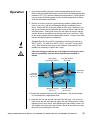
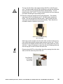
1
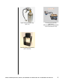
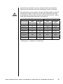
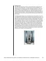
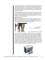
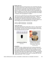
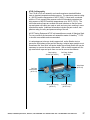
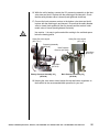
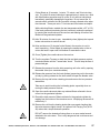
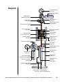
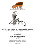
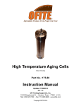
HTHP Filter Press for Ceramic Disks
with 175-mL, Double-Capped Test Cell and CO2 Pressuring Assemblies
#170-00-7: (115 V)
#170-01-6: (230 V)
Instruction Manual
Updated 12/30/2014
Ver. 1.2
OFI Testing Equipment, Inc.
11302 Steeplecrest Dr. · Houston, Texas · 77065 · U.S.A.
Tele: 832.320.7300 · Fax: 713.880.9886 · www.ofite.com
Copyright OFITE 2014
©
Table of
Contents
Introduction.....................................................................................2
Specifications..................................................................................3
Components....................................................................................4
Safety.............................................................................................. 11
Quick Start.....................................................................................19
Operation.......................................................................................22
Data.................................................................................................30
Maintenance...................................................................................31
Diagram..........................................................................................35
Warranty and Return Policy.........................................................36
OFITE, 11302 Steeplecrest Dr., Houston, TX 77065 USA / Tel: 832-320-7300 / Fax: 713-880-9886 / www.ofite.com
1
Intro
The OFI Testing Equipment (OFITE) High Temperature High Pressure
(HTHP) Filter Press is designed to evaluate drilling fluids, cement slurries,
fracturing and completion fluids under elevated temperatures and pressures.
Evaluating fluids under HTHP conditions similar to the downhole environment
is of paramount importance. Fluid properties must be monitored while under
high temperatures and pressures as filtration behavior and wall cake building
characteristics of permeable formations change with changing environments.
These characteristics are affected by the shape, type and quantities of solids
present in the fluid and their physical and electro-chemical interactions, all of
which are affected by changing temperatures and pressures.
OFITE manufactures and provides HTHP filtration units in two basic sizes,
175 mL and 500 mL capacities. Both are used extensively throughout the
world and in all environments, but in general the 175 mL units is designed for
field portability, while the larger 500 mL units are designed for laboratory usage at higher temperatures and pressures. All OFITE Filtration devices fully
conform to American Petroleum Institute (API) specifications.
A complete HTHP Filter Press consists of a controlled pressure source, usually Nitrogen pressurization or Carbon Dioxide bulbs for the 175 mL units.
Top and bottom pressure manifolds are provided to simulate the differential
pressures found in a down-hole environment, and to prevent evaporation of
the base fluid if exceeding the boiling point of that fluid. The test cells are
provided in a variety of assemblies, depending upon the type of fluid tested,
the filter media, and the temperatures and pressures desired. The test cells
are encased inside a heating jacket which is adjustable.
A variety of filter media are available, the most common being the standard
API filter paper, cement screens and ceramic filters, which may be obtained
to match the pore throat or permeability of the formation. Natural formation
cores may also be used of differing sizes. Different screens may be used, or
slotted disks of varying sizes are frequently used for lost circulation materials
studies
Both the 175 mL and the 500 mL heating jackets are capable of reaching 400°F (204°C), but lower fluid volumes due to fluid expansion at higher
temperatures, limit the 175 mL units to a useful working temperature of 300°F
(149°C) for water based fluids and 350°F (176°C) for non aqueous fluids.
Anyone running tests above 350°F (177°C) must substitute a complete set of
o-rings after each and every test.
OFITE, 11302 Steeplecrest Dr., Houston, TX 77065 USA / Tel: 832-320-7300 / Fax: 713-880-9886 / www.ofite.com
2
Specifications
Size:
Weight:
Shipping Size:
Shipping Weight:
Maximum Temperature:
Maximum Pressure (Cell):
Maximum Pressure (Receiver):
Pressure Source:
Test Cell Capacity:
Power Requirement:
Heater:
7.5" × 11" × 23.5" (19.1 × 27.9 × 59.7 cm)
27 lbs. (12.3 kg)
20" × 13" × 13" (51 × 33 × 33 cm)
33 lbs. (15 kg)
400°F (204°C)
1,500 PSI (10,343 kPa)
750 PSI (5.1 MPa)
Two CO2 Pressuring Assemblies
175 mL
#170-00-7: 115V; #170-01-6: 230V, 50/60 Hz
400 Watt
OFITE, 11302 Steeplecrest Dr., Houston, TX 77065 USA / Tel: 832-320-7300 / Fax: 713-880-9886 / www.ofite.com
3
Components
#153-14
#154-10
#170-19
#170-35
Graduated Cylinder, 50 mL × 1 mL
Dual-Scale Thermometer with Dial, 5" Stem, 50° - 500°F (0° - 250°C)
Filter Paper; 2½" (6.35 cm); Specially Hardened for Filter Presses
6" Adjustable Wrench
#170-04CO2 Pressurize Unit:
#143-02-10 CO2 Puncture Head Assembly
#143-02-12 Puncture Pin
#143-02-13 O-ring
#143-02-14 O-ring
#143-03
Barrel for CO2 Cartridge
#170-08
Regulator
#170-20
Manifold Block
#170-32
⅛" × ⅛" NPT Male Needle Valve
#171-23-1 Safety Pin with Lanyard
#171-34
1,500-PSI Gauge; 2"; ¼" NPT Bottom
#170-06 Back Pressure Receiver; 15-mL Stainless Steel Tube for CO2
#143-00
Regulator, Low Pressure
#143-01
200-PSI Gauge; ⅛" Bottom Connection
#143-02-10 CO2 Puncture Head Assembly
#143-02-12 Puncture Pin
#143-02-13 O-ring
#143-02-14 O-ring
#143-03
Barrel for CO2 Cartridge
#143-06
Safety Bleeder Valve
#144-11
⅛" 90 Street Ell
#170-07
O-ring
#170-28
Receiver Body
#170-32
⅛" × ⅛" NPT Male Needle Valve
#171-23-1 Safety Pin with Lanyard
#170-46 Double-Ended Test Cell for Ceramic Disks; 2000-PSI
#170-13-3 O-ring for Test Cell, Viton®/Fluorocarbon (FKM); Qty. 4
#170-16
Valve Stem; Qty. 2
#170-17
Valve Stem O-ring; Qty. 4
#170-26-1 Hardened Locking Screw; Qty. 12
#170-27
5⁄32" Allen Wrench
#170-47
Cell Body for Ceramic Disks, 175 mL, Double-Capped
#170-69
End Cap for Ceramic Disks, Scribed, 2,500 PSI
#170-72
Spacer for Filter Paper, ¼", 316 Stainless Steel
#170-77-1 O-ring, 140 Viton 75D, for Spacer; Qty. 2
#171-21
Cell Cap with 60-mesh Screen, 2,000 PSI
OFITE, 11302 Steeplecrest Dr., Houston, TX 77065 USA / Tel: 832-320-7300 / Fax: 713-880-9886 / www.ofite.com
4
#170-00-1Heating Jacket (115V) -OR#170-01-1Heating Jacket (230V):
#164-32
Male Connector for Power Cable (230 Volt)
#165-40-3 Power Cable, (For 170-01-1 230V Only)
#170-05
Thermostat
#170-10
Thermostat Pilot Light
#170-11
Heating Element; 115V; 200W
#170-15
Base
#170-21
Stand Support Rod
#170-25
Aluminum Well
#170-30
Stainless Steel Thermostat Cover
#170-44
Rubber Foot ½"; Qty: 4
#171-32
Midget Knob
#171-82
8' Power Cord with Male Plug 8; 16/3 SJ; Round (For 17000-1 115V Only)
Optional:
#143-05:
#152-00
#152-01
#155-20
#170-03:
#170-13
#170-13-5
#170-33:
#170-40:
#170-91
#170-92
EZ Puncture CO2 Bulbs; 8-Gram; UN #1013; Package of 10
Hamilton Beach Mixer, With Container
Armature For Model 936 H.B. Mixer, 115 Volt
Timer; 60 Min. Interval
Stainless Steel Carrying Case
O-ring for Test Cell, Buna, For tests below 300°F
O-ring for Test Cell, Ethylene propylene, For temperatures up to
400°F (204.4°C), Water-based fluids only
HTHP Cell Cap Puller
Test Cell Removal and Carrying Tool
HTHP Pressure Relief Tool
Safety Clamp for HTHP Fluid Loss Cells
OFITE, 11302 Steeplecrest Dr., Houston, TX 77065 USA / Tel: 832-320-7300 / Fax: 713-880-9886 / www.ofite.com
5
Optional:
#170-00-SP
Part Number
#140-60-01
#143-00-1
#143-01
#143-02-13
#143-02-14
#143-05
#143-07
#153-14
#154-10
#170-13-3
#170-16
#170-17
Spare partsfor 170-00, 175 mL HTHP Filter Press
Description
Quantity
O-ring for Bleeder Valve
2
Diaphragm for Concoa Regulator
1
Gauge. 200 psi, ⅛" Bottom Connection
1
O-ring for Puncture Pin Holder
2
O-ring for Puncture Pin Holder (rear)
2
60
CO2 Bulbs, 8 gram, 10 per pkg, UN1013
Repair Kit for Concoa Regulator
1
Graduated Cylinder, 50 mL × 1 mL
2
Dial Thermometer, 5" stem, 5-500°F & 0-250°C
1
O-ring for test cell and cap, Viton 75D
50
Valve Stem, for cell pressure and de-pressurization
4
O-ring, for Valve Stem, Viton 75D
48
#170-27
Filter Paper, 2 ½" (6.35 cm), hardened for
Filter Press, 100/box
Locking Cap Screw, Hardened Alloy Steel
Allen Wrench, 5/32"
#171-23-1
Safety Pin with Lanyard
#170-19
#170-26-1
5
12
1
1
Spare parts listings are intended to be used as a reference for future purchases. Everyone’s consumable requirements will be different, and replacement quantities needed will depend upon the number of test performed on a
daily and/or weekly basis.
OFITE, 11302 Steeplecrest Dr., Houston, TX 77065 USA / Tel: 832-320-7300 / Fax: 713-880-9886 / www.ofite.com
6
Optional Items for HTHP Filtration Testing:
The items listed below are not included in the HTHP Filter Press, but they are
items that will enable the technician to perform a more uniform and reproducible test while maintaining a high degree of safety. As optional items, the usage is not compulsory, but consideration should be given to these items when
running tests at elevated temperatures and pressures. Some of the items will
be used only on cell assemblies using set screws as fasteners, while others
should be implemented when operating all filtration equipment.
Interval Timer, 60 minute
(#155-20)
Cell Carrying Tool (#170-40)
Safety Clamp (#170-92)
(Set Screw Cell Assemblies Only)
Cell Cap Removal Tool
(#170-33)
(Set Screw Cell Assemblies Only)
HTHP Pressure Relief Tool
(#170-91)
(To release trapped pressure)
Safety Shield (#171-06)
OFITE, 11302 Steeplecrest Dr., Houston, TX 77065 USA / Tel: 832-320-7300 / Fax: 713-880-9886 / www.ofite.com
7
High Pressure Nitrogen Assy.
(#171-31)
Thermocouple Assembly
(#171-45-1)
(Direct temperature measurement
Of the fluid Inside the Cell)
Stand for HTHP Cell Assembly
(#171-190-028)
OFITE, 11302 Steeplecrest Dr., Houston, TX 77065 USA / Tel: 832-320-7300 / Fax: 713-880-9886 / www.ofite.com
8
Ceramic Disk Filters
Porous ceramic filters have many applications, but in the oil field they are
used as a replacement for filter paper in the HTHP Filter Press. Available in a
range of pore throat sizes and permeabilities, ceramic filters enable the operator to perform filtration tests under conditions similar to the formations being
drilled. This is a big advantage over the standard paper filters. Also ceramic
filters, unlike paper, have depth (usually ¼") so core analysis, invasion and
return permeability studies may all be performed. Bridging characteristics of
drilling and drill-in fluids may be analyzed.
Porous ceramics consists of closely-sized particles bonded together which
result in a uniform permeable material that forms a tortuous path for fluid
flow. The most common materials are Alumina and Silica, but there is an
almost unlimited variety of materials and shapes available. HTHP filtration
cell bodies must be recessed and extra ½" on the outlet side of the cell body
in order to accommodate the ceramic disk. A ¼" spacer is provided for usage
of filter paper if desired. Different sized ceramic disks to simulate cores and
an assortment of other pore throat porosities/permeabilities are available on a
special order bases.
These ceramic filters are classified by mean pore throat sizes and/or units
of permeability. Mean pore throat is the average minimum pore diameter
through the disk and it is measured in microns, or thousandths of a millimeter.
Permeability is measure of the volume flow of fluids through a porous or semi
porous media when subjected to a differential pressure. It is mathematically
equated by Darcy’s Permeability Law.
Previously mean pore throat size and permeability were roughly determined
using air permeameter technology. Recent research funded by the American
Petroleum Institute (API) used the latest Mercury Injection Capillary pressure
technology to determine these characteristics. This new procedure found that
the manufacturing process does not allow for absolute consistency between
ceramic batches, but after numerous tests over several years, the final results
was statistically pretty close. Even though the ceramic filters are the same
filters that have been provided for years, the new API method for determining
mean pore throat size and permeability have resulted in new and improved
OFITE, 11302 Steeplecrest Dr., Houston, TX 77065 USA / Tel: 832-320-7300 / Fax: 713-880-9886 / www.ofite.com
9
specifications as outlined in the chart. All results and all orders should be
based upon the information under the “New Mercury” column in the chart.
All ceramic disks must be soaked in the base fluid being tested for at least 30
minutes prior to usage. Failure to do so will result in premature and excessive plugging of the pores within the disks, giving erroneous results. Laboratories often will perpetually soak disks in the base fluid.
Mean Pore Throat (µm*)
New
Old Data
Part Number
(Mercury, Hg)
(Air)
#170-55
10
3
#170-53-2
12
5
#170-53-3
20
10
#170-51
40
20
#170-53
50
35
#170-53-1
55
60
#170-53-4
120
90
#170-53-5
-150
#170-53-6
-190
Mean Permeability (Darcy)
New
Old Data
(Mercury, Hg)
(Air)
775 mD
400 mD
850 mD
750 mD
3D
2D
8D
5D
15 D
10 D
20 D
20 D
40 D
100 D
-180 D
---
*1 Micron (µm) = 1/1,000 mm or 1/25,400 inch
OFITE, 11302 Steeplecrest Dr., Houston, TX 77065 USA / Tel: 832-320-7300 / Fax: 713-880-9886 / www.ofite.com
10
Safety
Pressure and Temperature Considerations
Do not use or reconfigure this equipment in a manner not specified in this
manual.
Pressure
There are two reasons for operating at elevated pressures when performing a
filtration analysis.
1. To test fluids at temperatures above the boiling point, the vessel must
be pressurized, which in turn elevates the vapor pressure (boiling
point) so that the fluid remains liquid and does not turn to steam.
2. If testing for drilling applications, pressurization will more approximate
down-hole conditions, enabling the technician to match both bottom
hole temperatures and pressures.
For temperatures less than 200°F (93°C) a Back Pressure Receiver is not
required as the filtrate will not reach the boiling point. However when operating above the boiling point of water, a suitable Back Pressure Receiver is
required, otherwise the test fluid will turn to steam and the test is invalidated.
The standard receiver tube supplied with the 175 mL HTHP Filter Press holds
15 mL of filtrate, so it is very important that the receiver outlet ball valve is
opened after approximately ten seconds of filtrate collection, as a fluid with
poor filtration qualities can easily fill the 15 mL receiver tube almost instantaneously. If this happens the filtrate hopefully will all be ejected from the
safety bleeder valve, but if there is too much fluid volume, the liquid may end
up inside the regulator rendering it useless which will require servicing by a
knowledgeable technician.
Nitrogen is commonly used as a pressure source. A small Nitrogen cylinder
(#170-37), size 21" × 7" (Optional) provides the pressure source. These cylinders are shipped empty, but when filled they may be pressurized to 2,216
PSI / 153 Bar. They have a standard CGA-580, Compressed Gas Association – left handed thread fitting connection. CGA 590 right handed thread
fittings are available upon request. A dual Nitrogen manifold assembly is
used and pressurizes both the top and the bottom or back pressure devices
simultaneously or individually as needed.
Temperature
Normally when one experiences a loss of pressure it is not due to a failure
of the metal alloy in the cell, but rather is a failure of the o-ring or elastomer,
which provides the seal. These o-ring may deform or melt under elevated
temperatures usually over 400°F (204°C) causing a pressurization failure of
the cell, which is often sudden and catastrophic. For example, if the valve
stem o-ring suddenly fails, then steam at 400°F and under great pressure
may shoot outward horizontally in one or several directions. A safety shield
should always be used when operating any HTHP Filter Press and especially
when one is going to extreme temperatures and pressures. Above 350°F
(176°C) All o-rings must be replaced after each and every test.
OFITE, 11302 Steeplecrest Dr., Houston, TX 77065 USA / Tel: 832-320-7300 / Fax: 713-880-9886 / www.ofite.com
11
Heating Jacket
Turn the thermostat knob on the front of the metal plate to change the temperature of the heating jacket. The thermostat cover is marked from 1 to
10 and each whole number represents a separate temperature. Each filter
press will heat up a little differently so it is a good idea to mark with a pen
directly on the face-plate of the thermostat cover the temperature which corresponds with each number. The actual temperature of the heating jacket is
measured with a stem thermometer and then the thermometer is placed into
the cell body.
The heating jacket will get very hot during the test so be careful not to touch
the outside of the jacket at any time during the heat-up period or the test. It is
especially easy to get burned when installing or removing the Back Pressure
Receiver as the technician is working in a very confined space. The power
cord is supplied for either 115 Volts or 230 Volts and due to the various types
of plug connectors around the world it may be necessary to change the plug
on the end of the power cord. The power cable is 8 feet in length and the
heating jacket should be placed no farther than 8 feet from the appropriate
electrical outlet. The heat up time will vary from one instrument to the next
and the pilot light will turn on when the set temperature has been reached.
The temperature of the fluid inside the cell however will not be at the set temperature, so always allow one hour of heating time for the fluid, after the cell
has been fully inserted into the heating jacket.
OFITE, 11302 Steeplecrest Dr., Houston, TX 77065 USA / Tel: 832-320-7300 / Fax: 713-880-9886 / www.ofite.com
12
The HTHP Filter Press is a very safe instrument to operate as long as the instructions are strictly followed. It is imperative that the technician thoroughly
understands the assembly and disassembly procedures and also why the
order of steps is in place. Care should be taken to never use defective parts
and that OFITE’s temperature, pressure, and fluid volume limits are strictly
adhered to at all times.
The heating jacket and cell will get very hot during the normal duration of the
test so the operator should take care to avoid burns. The operator should
be careful when attaching and removing pressure manifolds from the heating jacket, especially the Back Pressure Receiver assembly, which involves
operating in a small confined space.
Safety Retainer Pin
Always use a Safety Retainer Pin with an attached lanyard, and get in the
habit of securing the cotter pin to the pin. Improper placement of retainer
pins in the past have resulted in the pressure manifold separating from the
filter press which can cause damage to the equipment.
Retainer Pin with Lanyard
171-23-1 Safety Retainer Pin with Lanyard
The 175 mL HTHP Filter Press No. 170-00-3 and 170-01-3 uses Nitrogen
as the pressure source for both the inlet and the back pressure. Nitrogen is
more inert or less chemically reactive than carbon dioxide and therefore it is
used extensively in filtration control analysis where chemical reactions tend
to occur when subjected to elevated temperatures and pressures. A dual
Nitrogen manifold is supplied which regulates pressure to both the inlet and
outlet ends of the pressure cell. A single nitrogen regulator is available if dual
pressurization is not required. Nitrous Oxide (NO2) is available in the same
sized bulbs as CO2, but should never be used as a pressure source for HTHP
Filtration. Under high temperatures and pressures, nitrous oxide can detonate in the presence of grease, oil or carbonaceous material.
OFITE, 11302 Steeplecrest Dr., Houston, TX 77065 USA / Tel: 832-320-7300 / Fax: 713-880-9886 / www.ofite.com
13
Working Pressure
OFITE clearly stamps the working pressure of the cell assembly along with
the assembly serial number on each cell body and cell cap. These pressure
limits should never be exceeded on the pressure manifolds and fluid volumes inside the cell should strictly comply with instructions (see page 13).
However, in the past HTHP cells and caps from various manufacturers were
often not stamped, or in some cases, very old cell assemblies were stamped
“2500”. Cell assemblies with set screw secured caps should never be taken
to 2,500 PSI, under any temperature or condition.
The OFITE 175 mL HTHP Filter Press (#170-00 and #170-01) are furnished
with a standard 1500 PSI working pressure cell assembly. OFITE also
manufactures HTHP cells with a 2,000 PSI working pressure. Please note
the 1,500 PSI and 2,000 PSI cell assemblies do not have parts that are
interchangeable, so when ordering replacement cell caps for instance, know
which working pressure rated cell assembly you are ordering for.
Cell Cap, 1,500 PSI, Set Screws: 0.75 inch thick
Cell Cap, 2,000 PSI, Set Screws: 0.94 inch thick
Locking Set Screws
Locking set screws should have sharp points on the end. If the tip becomes
worn and flattened, pressure may be lost in the cell or the cell cap may become damaged. Any set screw cell cap that has elongated set screw holes
should be discarded as they are unsafe.
Locking Screw for HTHP Cell
Caps 2,000 PSI, 90 Cone Point
(#170-26-1)
#170-69 Cell Cap, 2,000 psi,
HTHP Filter Press Scribed For
Ceramic Filters. Note: Round
Set Screw Holes
O-ring Seals
The choice of o-rings, or elastomers as they are commonly called, is very
important in any high temperature high pressure environment. OFITE uses
Viton o-rings, a copolymer of Vinylidene, which are less pliable than some
Buna rings which may be encountered from other manufacturers, but they
withstand the higher temperatures better than the Buna rings. The maximum
temperature for the Viton o-rings is 400°F (204°C). OFITE suggests that all
o-rings (cell caps, cell bodies, and valve stem) are changed each time after
running a test of 350° F (176° C) or above.
OFITE, 11302 Steeplecrest Dr., Houston, TX 77065 USA / Tel: 832-320-7300 / Fax: 713-880-9886 / www.ofite.com
14
Fluid Expansion Space
Cells should never be filled completely with fluid. Always leave some room
for the fluid to expand under temperature. This keeps the cell caps from becoming overstressed and possibly leading to a cell pressure failure or even a
loss of the cell cap completely.
Periodically check all gauges to ensure the proper pressures are in the cell,
as the pressure often increases or decreases depending upon the test procedure and conditions.
API Recommended Void Space
Fluid / Temperature
Void Space
Fluid Volume
Water-based drilling fluid. < 300°F
0.6" (1.5 cm)
138 mL
Water-based drilling fluid. > 300°F
1.5" (4.0 cm)
86 mL
Oil-based drilling fluid. < 350°F (176°C)
1" (2.5 cm)
115 mL
Not RecommendedOil-based drilling fluid. > 350°F (176°C)
Use 500 mL Cell
Void Space in a 1,500 PSI rated cell body
OFITE, 11302 Steeplecrest Dr., Houston, TX 77065 USA / Tel: 832-320-7300 / Fax: 713-880-9886 / www.ofite.com
15
The OFI 175 mL HTHP Filter Press uses two regulators as standard equipment. Both may be operated with Carbon Dioxide (CO2) or Nitrogen (N2) gas.
1. Concoa Regulator 8051140-00-1: Top or Main Pressure.
a. Maximum Inlet Pressure – 3,000 PSI
b. ¼" NPT Connections
c. Single stage regulator
Regulator Safety
1. Never subject the regulator to inlet pressure greater than its rated inlet
pressure as shown on the regulator body.
2. Do not allow oil, oil bearing materials, grease, or other combustibles to
contaminate the inside or outside of the regulator, especially where Oxygen is in use.
3. To minimize heat effects, avoid the use of piping or tubing between the
pressurized cylinder and the regulator. If unavoidable it should be as
short as practical and equipped with a shutoff valve located just before
the regulator.
4. The 8051140 regulator has been internally cleaned for Oxygen but it is
not recommended to pressurize HTHP Filtration tests with Oxygen due to
its potentially explosive nature.
5. Never pressurize a regulator that has loose or damaged parts or is in
questionable condition. Never loosen a connection or attempt to remove
a part until gas pressure has been relieved.
6. Before transporting pressurized cylinders that are not secured on a cart
designed for such transport, remove all regulators and recap the cylinders.
7. Check the regulator and all connections for leaks after installation and periodically thereafter. Also check for leaks after any service in which parts
or connections were loosened. Brush with an approved leak detection
solution and bubbles should indicate a leakage.
8. An appropriately sized pressure relief device downstream of the regulator
should be installed in your system to prevent damage to equipment and/
or injury to personnel should an internal failure of the regulator occur.
9. Do not purge oxidizing or flammable gases in the presence of flame, lit
cigarettes, or other sources of ignition or towards people.
OFITE, 11302 Steeplecrest Dr., Houston, TX 77065 USA / Tel: 832-320-7300 / Fax: 713-880-9886 / www.ofite.com
16
HTHP Cell Assembly
The 170-46 HTHP cell assembly can handle maximum standard filtration
tests at elevated temperatures and pressures. The maximum pressure rating
is 1,500 PSI and the temperature is 400°F (204°C). Most tests, conducted
with the 175 mL capacity filter presses under API standards, operate at an
inlet pressure of 600 PSI and with temperatures up to 350°F (176°C). The
cell bodies and cell caps are scribed with serial numbers so that the same
cap and same cell bodies are used on each and every test, resulting in more
reproducible results. Additional information includes the part number, temperature rating, the alloy and pressure rating of the cell.
All OFI Testing Equipment HTHP cell assemblies are made of Stainless Steel.
For very corrosive environments cell assemblies made of HastelloyTM C-276
or Inconel are available and recommended.
It is advantageous to have a double capped cell, as the filtration test removes the liquid phase of the test fluid leaving a relative larger particle count.
Sometimes this “semi-fluid’ will harden inside the cell body and a drill may be
necessary to remove the now solid material. With a double capped cell simply remove both caps and push from one end to remove the contents.
Cap Locking
Screws (#170-26-1)
Cell Cap, Scribed
(#170-69)
Valve Stem
(#170-16)
Cell Cap
with Screen
(#171-21)
Valve Stem O-ring
(#170-17)
Cell Cap O-ring
(#170-13-3)
OFITE, 11302 Steeplecrest Dr., Houston, TX 77065 USA / Tel: 832-320-7300 / Fax: 713-880-9886 / www.ofite.com
17
CO2 Pressuring
Assembly
(#170-04)
Valve Stem
(#170-16)
Cell Assembly
(#170-46)
Heating Jacket
(#170-00-1 / #170-01-1)
Back Pressure
Receiver (#170-06)
Base
(#170-15)
Regulator
(#170-08)
Gauge 1500 psi
(#171-34)
T-Screw
Relief Valve
(#143-06)
Retaining Pin
T-Screw
With Lanyard
(#171-23-1)
Gauge 200 psi
(#143-01)
Barrel for CO2 Bulb
(#143-03)
Regulator
(#143-00)
Receiver
Body
(#170-28)
Needle Valve (#170-32)
Retaining Pin (#171-23-1)
With Lanyard
Manifold
Block
(#171-34)
CO2 Pressuring Assembly
(#170-04)
Barrel for CO2 Bulb
(#143-03)
Needle Valve (#170-32)
Back Pressure Receiver
(#170-06)
OFITE, 11302 Steeplecrest Dr., Houston, TX 77065 USA / Tel: 832-320-7300 / Fax: 713-880-9886 / www.ofite.com
18
Quick Start
1. Pre-heat the heating jacket to 10°F (6°C) above the desired test temperature.
a. Thermometer in jacket.
b. Thermostat light turns on when target temperature is reached.
2. O-rings:
a. Inspect o-rings and install in cell body, cell caps and on valve stems.
b. Coat all cell o-rings with Silicone Stopcock Grease, #153-55.
3. Cell Assembly:
a. Install inlet cell cap, being sure the arrows on lid and cell body align.
b. Set screws – Ensure the set screw points are sharp. Tighten the set
screws completely.
c. Install the valve stem on the inlet side of cell body.
4. Invert cell and pour sample into the cell leaving at least 0.6 inches (1.5
cm) void space to allow for heat expansion.
a. Do not spill fluid on the o-ring groove.
5. Place a pre-soaked ceramic filter of your choice on top of the o-ring.
6. Push the outlet cell cap into the cell, making sure the arrows align.
a. Valve stem initially open to facilitate insertion.
b. Tighten set screws
c. Close (tighten) the outlet valve stem. Both valve stems are closed
and the cell is sealed.
7. Invert and place the cell inside the heating jacket and rotate the cell until it
seats. Hour heat-up time begins now.
8. Transfer the thermometer from the heating jacket to the cell body.
9. Connect the inlet (top) pressure assembly and lock in place with the retaining pin.
10.Connect the back pressure assembly and lock in place with the retaining pin.
11.Puncture CO2 bulbs - Adjust inlet/back pressure regulators to desired
back pressure.
OFITE, 11302 Steeplecrest Dr., Houston, TX 77065 USA / Tel: 832-320-7300 / Fax: 713-880-9886 / www.ofite.com
19
12.Open (loosen) the inlet (top) valve stem a ½ turn to pressurize the cell.
13.Heat for one hour. The thermometer should register at the target temperature within an hour. Total heat up time should not to exceed 1 hour.
14. After the hour heat up time, increase pressure on inlet (top) pressure unit
to 500 PSI over the back pressure.
15.Open bottom valve stem to initiate filtration.
16.Collect and note filtrate amount at 10 seconds, 1.0, 7.5 and 30.0 minutes.
a. 10 sec. collection is cautionary as a fluid with poor filtration control
can quickly fill up the receiver.
b. If back pressure raises above 100 PSI reduce the pressure by opening the ball valve.
17.Collect filtrate for a total of 30 minutes, maintaining inlet and back desired
pressures.
18. After 30 minutes, close (tighten) inlet and outlet valve stems to seal off the
cell.
19. Turn top and bottom regulator T-screws counter clockwise to release
pressure.
20.Open the outlet valve on the back pressure receiver to collect all the filtrate in the graduate cylinder.
21.Open the needle or bleeder valves on both the top and back pressure
units.
22.Remove the top and bottom retainer pins and remove pressuring units
from the cell.
23.Drain any residual filtrate collected from the top of the receiver into the
graduate cylinder.
24.Remove the cell from the heating jacket and allow to cool to room temperature (outlet side down).
25.Open (Loosen) the inlet valve stem to relieve pressure on the cell. There
should be a noticeable release of pressure.
26.Loosen the 6 cap locking screws on the outlet cap.
27.Carefully remove the outlet cell cap.
OFITE, 11302 Steeplecrest Dr., Houston, TX 77065 USA / Tel: 832-320-7300 / Fax: 713-880-9886 / www.ofite.com
20
28.Wash the filter cake with gentle stream of water and record thickness to
nearest 1/32 inch.
29.Clean and dry filter press jacket, cell and pressure assemblies thoroughly.
30.Inspect and replace any or all o-rings - All if test run > 300°F (149°C).
31.Report: Double the filtrate volume - Correct to the API standard of 7.1 in2.
Spurt Loss volume is Optional.
OFITE, 11302 Steeplecrest Dr., Houston, TX 77065 USA / Tel: 832-320-7300 / Fax: 713-880-9886 / www.ofite.com
21
Operation
1. Connect the heating well power cord to an appropriate power source.
Place a dial-type metal thermometer into the well in the heating jacket and
preheat to 10°F (6°C) above the desired test temperature. A pilot light will
come on when the heating jacket is at the desired temperature as selected by the thermostat control knob.
2. Be sure all of the o-rings are in good working condition (pliable with no
nicks or cuts, etc.), and are not damaged during the assembly procedures. Place a thin film of silicone grease on all o-rings. Place an o-ring
into one end of the test cell and place the screen on top of it with the flat
side facing down. Slowly push one of the cell caps into the cell, making
sure the arrow on the cap lines up with the arrow on the cell body. Tighten the locking screws with the supplied Allen wrench. Screw a valve stem
into the cell cap and tighten it completely.
Standard Buna N o-rings (#170-13) should be used only for tests up to
300°F (149°C). For tests over 300°F (149°C), use Viton® o-rings (#17013-3). After tests that come close to the maximum temperature, it will
probably be necessary to replace the o-rings.
If the cap locking screw seats are oval shaped and no longer round,
there is a possibility of stress failure and the cap should be replaced.
Cap Locking
Screws (#170-26-1)
Cell Cap, Scribed
(#170-69)
Valve Stem
(#170-16)
Cell Cap
with Screen
(#171-21)
Valve Stem O-ring
(#170-17)
Cell Cap O-ring
(#170-13-3)
3. Prepare the sample according to API specifications. Stir the test sample
for 10 minutes with a high speed mixer.
4. Install the inlet cell cap into the inlet end of the cell body. Line up the arrows on the cap and cell body and tighten the cap locking screws, initially
tightening every other screw. After tightening the cap locking screws, run
your fingers around the cell body to ensure that all of the screws are tight
and none are protruding from the wall.
OFITE, 11302 Steeplecrest Dr., Houston, TX 77065 USA / Tel: 832-320-7300 / Fax: 713-880-9886 / www.ofite.com
22
5. Place two o-rings in the o-ring grooves on each valve stem. Screw one
valve stem into the cell cap on the inlet side of the cell. Tighten the valve
stem completely. To increase the life of the valve stem and cap, apply a
thin layer of high-temperature thread lubricant (#165-44) to the conical
face o-ring on the pointed end of the valve stem.
6. Invert the cell body and carefully pour the sample into the cell, leaving the
appropriate amount of void space as indicated by the chart below. Be
careful not to spill fluid on the o-ring inside the cell.
Temperature – Pressure – Volume: Recommendations
Be Careful Not to spill fluid on the O-ring Groove inside the Cell
API Recommended Void Space
Fluid / Temperature
Void Space
Fluid Volume
Water-based drilling fluid. < 300°F
0.6" (1.5 cm)
138 mL
Water-based drilling fluid. > 300°F
1.5" (4.0 cm)
86 mL
Oil-based drilling fluid. < 350°F (176°C)
1" (2.5 cm)
115 mL
Oil-based drilling fluid. > 350°F (176°C)
Use 500 mL Cell
Void Space in a 1,500 PSI rated cell body
7. Place an o-ring in the cell and another on the outlet cell cap (they are the
same sized o-ring). To facilitate removing the cell cap at the end of the
test, lightly apply a coat of stopcock grease (#153-55) to the cell cap o-ring.
8. Inspect the cap locking screws. If the cap locking screw are no longer
sharply pointed, there is a possibility of stress-failure and the screw(s)
should be replaced.
9. Inspect the cap locking screw seats in the cell cap (indentures in the cell
cap). If the cap locking screw seats are no longer round, there is a possibility of stress failure and the cap should be replaced.
10.Place a pre-soaked ceramic disk filter on top of the cell o-ring and gently
push it downward so it contacts the o-ring.
OFITE, 11302 Steeplecrest Dr., Houston, TX 77065 USA / Tel: 832-320-7300 / Fax: 713-880-9886 / www.ofite.com
23
11. Make sure the arrow on the cell cap lines up with the arrow on the cell
body and slowly push the cell cap into the cell. Ensure that the o-ring
does not slip out of the o-ring groove during insertion of the cell cap. Not
attaching or tightening the valve stem makes this operation easier.
Arrows
12. Use the Allen wrench to tighten the six locking set screws into the cell and
secure the cell cap in place. Use hand-touch to make sure that all of the
set screws are completely tightened. The cell may become permanently
stuck inside the heating jacket if one or more set screws are left protruding from the cell.
13. Install a valve stem into the cell cap and tighten completely with a wrench.
14. Hold the valve stem and place the cell in the heating jacket with the outlet
(filter) side of the cell pointed down. Using the wrench, rotate the cell
inside the heating jacket so that the pin in the bottom of the heating well
seats into the hole in the bottom of the test cell. This will anchor the cell
in the well and prevent it from rotating as the valve stems are opened and
closed. Check the inlet and outlet valve stems with a wrench to ensure
they are tight.
15. Move the thermometer from the heating jacket to the hole in the test cell.
The heating time of the sample should take exactly one hour. Set a timer
to 60 minutes and begin the test at this time.
Do not initiate filtration when the thermometer first indicates the desired
temperature has been reached. The fluid inside the cell may not have
yet reached the proper temperature. An api funded project found that for
most fluids, it usually takes upwards of an hour for the fluid inside the cell
to reach the target temperature. If accurate temperature measurement is
required during the heating portion of the test, a thermocouple assembly
(#171-45-1) is available which will directly and accurately measure the
fluid temperature inside the cell.
OFITE, 11302 Steeplecrest Dr., Houston, TX 77065 USA / Tel: 832-320-7300 / Fax: 713-880-9886 / www.ofite.com
24
16. While the cell is heating, connect the CO2 pressuring assembly to the inlet
valve stem and lock it in place with the retaining pin and lanyard. Check
that the safety bleeder valve is closed (knob tightened clockwise).
17. Connect the back pressure receiver to the bottom valve stem and lock it
in place with the retaining pin and lanyard. Ensure that the safety bleeder
valve is closed (knob pushed all the way inward) and the receiver outlet
needle valve is closed (knob tightened clockwise).
Use caution. It is easy to get burned while working in the confined space
below the heating jacket.
Safety Pin with Lanyard
(#171-23-1)
Safety Pin with Lanyard
(#171-23-1)
Pressuring Assembly
(#170-04)
Back Pressure
Receiver (#170-06)
Valve Stem
(#170-16)
Valve Stem
(#170-16)
Primary Pressure Assembly, CO2
(#170-04)
Back Pressure Assembly, CO2
(#170-06)
18.Keeping the valve stems closed, adjust the top and bottom regulators on
the manifold to the recommended back pressure for your test.
OFITE, 11302 Steeplecrest Dr., Houston, TX 77065 USA / Tel: 832-320-7300 / Fax: 713-880-9886 / www.ofite.com
25
The upper and lower limits of the test pressure differential are determined
by the test temperature. If the test is conducted at a temperature less
than the boiling point of water, then no back pressure will be required and
filtrate may be collected directly into a graduated cylinder. If however
tests are conducted above the boiling point of water, then as this temperature exceeds 212°F (100°C), the back pressure must be increased
above the vapor pressure, at the test temperature, in order to prevent
vaporization of the filtrate. If running a standard API test, the 500 PSI differential pressure must be maintained, so the top pressure will have to be
increased 500 PSI over whatever the back pressure is. The table below
shows the back pressures recommended for various test temperatures.
Recommended Minimum Back Pressure
Test Temperature
°F
212
250
300
350
400
450
°C
100
121
149
177
204
262
Vapor Pressure
PSI
14.7
30
67
135
247
422
kPa
101
207
462
932
1,704
2,912
Minimum Back Pressure
PSI
100
100
100
160
275
450
kPa
690
690
690
1,104
1,898
3,105
19. Open (loosen) the Inlet valve stem ½ turn to pressurize the sample.
Maintain this pressure on the fluid until the temperature has stabilized.
This will prevent vaporization of the test solution if heating above the boiling point of the liquid.
20. After the one hour heat up time, increase the pressure on the inlet pressure unit to 500 PSI (3,448 kPa) more than the back pressure.
21. Open (loosen) the bottom valve stem ½ turn to initiate filtration as soon as
possible. Start the filtration test at this time. Set a timer to 30 minutes. If
spurt loss is being measured, set a second timer to 7.5 minutes.
Closely monitor the pressure gauges. If at any time during the test the
pressure inside the cell rises above the setpoint, carefully open the
needle valve on the top pressure assembly just enough to bleed off the
excess pressure. Then close the valve. If the cell pressure decreases
due to collection of filtrate, increase the pressure with the inlet regulator.
22. To collect filtrate, carefully open the needle valve on the bottom of the
back pressure receiver while holding a graduated cylinder to the valve
port. Close the valve immediately after the outlet pressure just begins to
avoid having to replace a CO2 bulb in the middle of the test.
OFITE, 11302 Steeplecrest Dr., Houston, TX 77065 USA / Tel: 832-320-7300 / Fax: 713-880-9886 / www.ofite.com
26
Collect filtrate at 10 seconds, 1 minute, 7.5 minute, and 30 minute intervals. The initial 10 second collection is precautionary in nature, as a fluid
with little filtration properties may fill up the 15 mL receiver tube almost
immediately, potentially damaging the regulator. Do not record the 10
second volume collected, but do record the volume collected at the other
time intervals. Timers pre-set to 7.5 minutes and 30 minutes are helpful.
While collecting filtrate, maintain the test temperature within ± 5°F (±3°C).
If the back pressure rises during the test, cautiously reduce the pressure
by opening the needle valve on the receiver and drawing off some of the
filtrate into the graduated cylinder.
23. After 30 minutes, the test is over. Immediately close (tighten) the top and
bottom valve stems to seal off the cell.
24. Allow a minimum of 5 minutes for the filtrate in the receiver to cool to
avoid vaporizing. Collect filtrate by opening the needle valve on the receiver and leave it open until fluid ceases to evacuate the valve.
25. Close (Tighten) the needle valve on the receiver.
26. Turn the regulator T-screws on both the inlet and back pressure receiver
counterclockwise until the T-screw feels “loose”. This will stop the flow of
pressurized gas.
27. Release the pressure from the Inlet pressuring unit to the cell by opening
the needle valve (turn counterclockwise).
28.Release the pressure from the back (bottom) pressuring unit to the receiver body by pulling outward on the knob which will open the bleeder valve.
29. Remove the top and bottom retaining pins and remove the two pressure
assemblies.
Take care to avoid touching the hot heating jacket, especially when removing the back pressure receiver.
30. Open the needle valve and drain any residual filtrate collected in the receiver into the graduated cylinder.
31.Record the total amount of filtrate collected in the graduate cylinder by
reading from the bottom of the meniscus curve. Multiplying the amount in
milliliters by 2.
32. Remove the cell from the heating jacket after once again checking that
the valve stems are tightly closed. An optional Cell Carrying Tool (#17040) makes this a simple and safe operation.
DO NOT remove the heated cell using pliers or an open ended wrench
attached to the valve stem. This is very dangerous and could cause serious damage.
OFITE, 11302 Steeplecrest Dr., Houston, TX 77065 USA / Tel: 832-320-7300 / Fax: 713-880-9886 / www.ofite.com
27
The test cell will still be under approximately 600 PSI (4.140 kPa) pressure. To avoid possible serious injury, position the cell with the outlet end
down and cool it to room temperature before disassembling. The cell
must be below 100°F (38°C). Cool for at least one hour at room temperature before loosening the cap locking screws.
33. Place the cooled cell upright with the outlet side down. The optional
stand for the HTHP cell assembly (#171-190-028) makes a great cell
holder. This will help preserve the filter cake. Open (loosen) the inlet
valve stem to bleed off pressure from the cell body. There should be a
noticeable release of pressure from the cell.
Stand for HTHP Cell Assembly
(#171-190-028)
Hold a rag or piece of paper over the valve stem in order to catch any liquid or solids that might be ejected under pressure from the cell. This will
help prevent an unsightly residue build up on the ceiling which may occur
over time. It may be necessary to return the cell to the heating jacket and
use the stop-pin in order to loosen the valve stem.
Pressure should NOT be relieved from the cell by opening the outlet valve
stem as the filter cake may seal off the cell.
Safe Release
of Pressure
from a Cell
OFITE, 11302 Steeplecrest Dr., Houston, TX 77065 USA / Tel: 832-320-7300 / Fax: 713-880-9886 / www.ofite.com
28
A good indication that pressure is trapped inside the cell body occurs if
the set screws are unusually difficult to loosen (especially the 4th, 5th,
and 6th ones) and the cell cap begins to extrude out of the cell body as
the set screws are progressively loosened. To relieve any trapped pressure, an OFITE Pressure Relief Tool (#170-91) may be inserted through
the inlet cell cap hole which will relieve any trapped pressure inside the
cell. Ensure this function is performed on the inlet side of the cell as the
filter cake may seal off the outlet end of the cell.
34. Invert the cell and loosen, but do not remove, the six cap locking screws,
and separate the cap from the cell with a slight rocking motion. The
OFITE Cell Cap Removal Tool (#170-33) makes it easy to remove tight
difficult to remove cell caps.
35. There are several ways to remove the filter along with the filter cake.
a. Hold the cell and invert it over a sink and let the weight of the fluid
inside the cell push the disk out.
b. A spatula might help in prying out the ceramic disk.
c. With the outlet cell cap removed, re-attach the Inlet CO2 pressure assembly and apply enough pressure to extrude the ceramic disk.
36. Discard the fluid inside the cell unless it is required for further testing.
Save the filter cake for analysis.
37. Clean and dry the apparatus thoroughly after each use.
38. Inspect all o-rings for deformities and replace as necessary. Replace all
o-rings if the test was conducted above 350°F.
After each test, the HTHP filter press should be left so that a new test may be
performed with no clean-up and a minimum of assembly.
OFITE, 11302 Steeplecrest Dr., Houston, TX 77065 USA / Tel: 832-320-7300 / Fax: 713-880-9886 / www.ofite.com
29
Data
Filtrate Volume
The HTHP filter press has a filtration area of 3.55 in2 (22.9 cm2). This is half
the area of a standard filtration test, which is 7.1 in2 (45.8 cm2). To compare
the results of this test to a standard filtration test, double the total filtrate volume collected for the full 30 minutes.
VS = 2 (V30)
Spurt Loss (Optional)
Spurt Loss is the amount of filtrate collected before the filter cake has had a
chance to form and is expressed in millimeters. To calculate the spurt loss,
use the following equation:
V1 = 2 [V7.5- (V30 - V7.5)] = 2 (2V7.5 - V30) = 4V7.5 - 2V30
Where:
Vs = Standard Filtrate Volume (mL)
V1 = Spurt Loss
V7.5= Filtrate volume in milliliters collected after 7.5 minutes (doubled)
V30= Filtrate volume in milliliters collected after 30 minutes (doubled)
Filter Cake
Wash the filter cake on the paper with a gentle stream of water. Measure and
report the thickness of the filter cake to the nearest 1/32" (0.8 mm). A ruler with
the “zero mark” at the very edge of the ruler is useful here. Cake descriptions
may be subjective and such notations such as hard, soft, rubbery, and fine,
etc. convey adequate information on cake quality.
OFITE, 11302 Steeplecrest Dr., Houston, TX 77065 USA / Tel: 832-320-7300 / Fax: 713-880-9886 / www.ofite.com
30
Maintenance
1. HTHP cell assemblies should periodically be checked
for:
a. Cell Corrosion – Stress cracking or pitting
b. Cylinder Shear – Raised areas above the cell set
screw holes
c.
Elongated set screw holes in the cell bodies
d. End Cap Compression – Elongated set screw depressions on cell caps
e. Set screws which are no longer tapered on the
inside
f.
Elastomers – Check for flat spotting and melting
g. Valve stems should be sharply pointed and not dull on outlet side.
2. Always thoroughly clean up after each tests.
a. Replace all elastomers if previous test was in excess of 300°F
(149°C).
b. Clean out and blow dry if possible, the back pressure receiver.
c. Cell body must be completely cleaned with special attention to the oring groove.
3. Periodically check for leaks.
a. Cell Assembly – Immerse sealed pressurized cell assembly in a sink
filled with water – look for bubbles.
b. Top Pressure Assembly – Immerse regulator, valves, and sealed cell
assembly in a sink full of water and look for bubbles. Hold assembly
by the gauge and do not let the gauge get wet.
c. Back Pressure Receiver – Similar to “B”. Hold assembly by the gauge
and do not allow it to get wet.
OFITE, 11302 Steeplecrest Dr., Houston, TX 77065 USA / Tel: 832-320-7300 / Fax: 713-880-9886 / www.ofite.com
31
4. Regulator and Manifold Maintenance
a. Replace both o-rings on the puncture pin (#143-02-13 and #143-0214) at least once a year.
b. If the regulator loses pressure or steadily increases in pressure, replace the seat assembly and diaphragm.
Concoa Repair Kit – Part #143-07. Normally the Concoa regulator is
supplied with the 175 mL models
The Large High Pressure Concoa Regulator (805-1140) and the
smaller Concoa Regulator (805-1179) both take the same Regulator
Repair Kit
Always replace (order separately) the rubber diaphragm, #143-00-1,
which is not supplied with the #143-07 kit.
Diaphragm
(#143-00-1)
Repair Kit
(#143-00-1)
OFITE, 11302 Steeplecrest Dr., Houston, TX 77065 USA / Tel: 832-320-7300 / Fax: 713-880-9886 / www.ofite.com
32
Regulator Maintenance and Trouble Shooting
Symptoms
Gas leak at the regulator outlet when
the adjusting screw is loosened fully
counterclockwise
Outlet pressure increases while
downstream valves are closed
Gas leak from the spring housing
case
Excess drop in outlet pressure with
the regulator flow open
Gas leak from any pipe thread joint
Gas leak from relief valve
Inconsistent repeat readings
Gauge does not return to zero with
no pressure applied to the regulator.
Cause: Resolution
Seat leak or *creep: Repair the
regulator
Seat leak or *creep: Repair the
regulator
Diaphragm failure: Repair the regulator
Blocked seat assembly or inlet filter:
Repair the regulator
Loose fitting: Remove the connection. Clean the affected surfaces.
Reapply Teflon tape and tighten.
Faulty relief valve: replace the valve.
Seat leak or *creep: Repair the
regulator
Seat sticking: Repair the regulator.
Bad pressure gauge: Replace the
gauge.
Gauge has physical damage: Replace the gauge.
*Creep is an increase in outlet pressure that occurs when pressure escapes even when the
valve is closed. Regulator seats can be compromised by particles in the process stream
which can cause minor imperfections in the sealing surface. The high flow and small orifice
created during pressure regulation combine to turn a very small particle into a fast projectile.
This projectile can nick the sealing surface of the seat and cause leaks. Filtering particulates from the process stream should be a high priority, and a small filter can reduce the
potential for creep and increase the life expectancy and accuracy of the regulator.
OFITE, 11302 Steeplecrest Dr., Houston, TX 77065 USA / Tel: 832-320-7300 / Fax: 713-880-9886 / www.ofite.com
33
To replace the Seat Assembly:
1. Unscrew the spring case (housing cover). This may require a strap
wrench.
2. Remove the spring case.
3. Remove the rubber diaphragm (#143-00-1) from inside the spring case.
4. Remove the thrust plate (#143-00-7).
5. Using a wrench, loosen and remove the brass colored retainer.
6. The thrust pin and seat are now exposed and can be removed from
the base.
7. Replace the spring – repair kit.
8. Replace the seat holder – repair kit.
9. Replace the thrust pin and the Teflon seat which can be attached before insertion-repair kit.
10.Replace the brass retainer and tighten with a wrench.
11.Replace the thrust plate with the curved edges downward.
12.Place a new rubber diaphragm inside the Soring case
13.Replace the spring case and hand tighten.
Power Cord Maintenance
a. Check power cord for Insulation wear and loose connections near the
heating jacket and plug.
b. The heating jacket should be placed no farther than the distance of
the power cord from an electrical outlet.
c. The Power Cord should be kept away from the hot surface of the
heating jacket, while in use.
Any customer installed wiring, power cords or electrical connectors
will Void All Warranties.
Storage Space
a. Consumables and tools should all be kept in one dedicated place.
b. Components such as manifold assemblies should be kept in a similar
dedicated place.
OFITE, 11302 Steeplecrest Dr., Houston, TX 77065 USA / Tel: 832-320-7300 / Fax: 713-880-9886 / www.ofite.com
34
Diagram
1,500-PSI Gauge
(#171-34)
Barrel for CO2 Bulb
(#143-03)
High-Pressure
Regulator (#170-08)
Needle Valve
(#170-32)
Valve Stem (#170-16)
Valve Stem O-ring
(#170-17)
Heating Jacket
(#170-00-1/#170-01-1)
Cell Cap, Scribed
(#170-69)
Regulator (#143-00)
Manifold Block
(#170-20)
Safety Pin (#171-23-1)
With Lanyard
Cell Cap with Screen
(#171-21)
Test Cell Body
(#170-45-3)
Test Cell O-ring
(#170-13-3)
Locking Screw
(#170-26-1)
Valve Stem
(#170-16)
Safety Pin (#171-23-1)
With Lanyard
200-PSI Gauge
(#143-01)
CO2 Puncture Head
Assembly (#143-02-10)
Barrel for CO2 Bulb
(#143-03)
Receiver Body
(#170-28)
Support Rod
(#170-71)
Receiver O-ring
(#170-07)
(Not Shown)
Safety Bleeder Valve
(#143-06)
Needle Valve 1/8" 90 Street Ell
(#170-32) (#144-11) (Not Shown)
OFITE, 11302 Steeplecrest Dr., Houston, TX 77065 USA / Tel: 832-320-7300 / Fax: 713-880-9886 / www.ofite.com
35
Warranty and
Return Policy
Warranty:
OFI Testing Equipment, Inc. (OFITE) warrants that the products shall be free from liens and defects in
title, and shall conform in all respects to the terms of the sales order and the specifications applicable to
the products. All products shall be furnished subject to OFITE’s standard manufacturing variations and
practices. Unless the warranty period is otherwise extended in writing, the following warranty shall apply:
if, at any time prior to twelve (12) months from the date of invoice, the products, or any part thereof, do not
conform to these warranties or to the specifications applicable thereto, and OFITE is so notified in writing
upon discovery, OFITE shall promptly repair or replace the defective products. Notwithstanding the foregoing, OFITE’s warranty obligations shall not extend to any use by the buyer of the products in conditions
more severe than OFITE’s recommendations, nor to any defects which were visually observable by the
buyer but which are not promptly brought to OFITE’s attention.
In the event that the buyer has purchased installation and commissioning services on applicable products,
the above warranty shall extend for an additional period of twelve (12) months from the date of the original
warranty expiration for such products.
In the event that OFITE is requested to provide customized research and development for the buyer,
OFITE shall use its best efforts but makes no guarantees to the buyer that any products will be provided.
OFITE makes no other warranties or guarantees to the buyer, either express or implied, and the warranties
provided in this clause shall be exclusive of any other warranties including ANY IMPLIED OR STATUTORY
WARRANTIES OF FITNESS FOR PURPOSE, MERCHANTABILITY, AND OTHER STATUTORY REMEDIES WHICH ARE WAIVED.
This limited warranty does not cover any losses or damages that occur as a result of:
•
Improper installation or maintenance of the products
•
Misuse
•
Neglect
•
Adjustment by non-authorized sources
•
Improper environment
•
Excessive or inadequate heating or air conditioning or electrical power failures, surges, or other
irregularities
•
Equipment, products, or material not manufactured by OFITE
•
Firmware or hardware that have been modified or altered by a third party
•
Consumable parts (bearings, accessories, etc.)
Returns and Repairs:
Items being returned must be carefully packaged to prevent damage in shipment and insured against possible damage or loss. OFITE will not be responsible for equipment damaged due to insufficient packaging.
Any non-defective items returned to OFITE within ninety (90) days of invoice are subject to a 15% restocking fee. Items returned must be received by OFITE in original condition for it to be accepted. Reagents
and special order items will not be accepted for return or refund.
OFITE employs experienced personnel to service and repair equipment manufactured by us, as well as
other companies. To help expedite the repair process, please include a repair form with all equipment
sent to OFITE for repair. Be sure to include your name, company name, phone number, email address,
detailed description of work to be done, purchase order number, and a shipping address for returning the
equipment. All repairs performed as “repair as needed” are subject to the ninety (90) day limited warranty.
All “Certified Repairs” are subject to the twelve (12) month limited warranty.
Returns and potential warranty repairs require a Return Material Authorization (RMA) number. An RMA
form is available from your sales or service representative.
Please ship all equipment (with the RMA number for returns or warranty repairs) to the following address:
OFI Testing Equipment, Inc.
Attn: Repair Department
11302 Steeplecrest Dr.
Houston, TX 77065
USA
OFITE also offers competitive service contracts for repairing and/or maintaining your lab equipment, including equipment from other manufacturers. For more information about our technical support and repair
services, please contact [email protected].
OFITE, 11302 Steeplecrest Dr., Houston, TX 77065 USA / Tel: 832-320-7300 / Fax: 713-880-9886 / www.ofite.com
36