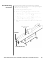
1
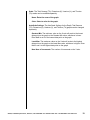
OFITE Spectral Gamma Ray Logger
Part No.: 700-410
Instruction Manual
Updated 4/27/2015
Ver. 1.12
OFI Testing Equipment, Inc.
11302 Steeplecrest Dr. · Houston, Texas · 77065 · U.S.A.
Tele: 832.320.7300 · Fax: 713.880.9886 · www.ofite.com
Copyright OFITE 2014
©
Table of
Contents
Introduction.....................................................................................2
Description.......................................................................................2
Specifications..................................................................................2
Components....................................................................................2
Quick Start.......................................................................................3
Operation.........................................................................................4
Data Export......................................................................................7
Manual Control................................................................................8
Calibration......................................................................................10
Spectral......................................................................................10
Belt.............................................................................................15
Software Setup..............................................................................16
Troubleshooting............................................................................20
Belt Adjustment..........................................................................20
Idler Adjustment.........................................................................21
Limit Switch................................................................................21
Belt Speed.................................................................................22
Maintenance...................................................................................23
Warranty and Return Policy.........................................................24
OFITE, 11302 Steeplecrest Dr., Houston, TX 77065 USA / Tel: 832-320-7300 / Fax: 713-880-9886 / www.ofite.com
1
Introduction
The natural gamma ray radiation emitted from rocks varies with the lithology.
The radiation comes from the radioactive decay of Potassium, Uranium, and
Thorium, which are present as trace elements. Shale typically contains more
of these elements than clean sandstone or limestone. Generally, formations
with higher shale content release more radiation.
A gamma ray well log is a recording of the natural gamma radiation of the
formation around the well bore and is almost always run in conjunction with
other well logs. Because the gamma ray log does not change with well treatment or production, it can be used to correlate the depths of the other well
logs and the core gamma ray log from the same hole.
The OFITE Gamma Ray Core Logger measures the energy level and quantity of the radiation emitted from a core sample and calculates the quantity of
each of the elements. The amounts of each of these elements and the total
gamma-ray count are then plotted as a function of depth.
Description
To begin a test, the operator arranges the core samples onto the conveyor
belt in order of depth. The unit will record background radiation for 15 minutes
in order to establish a base reading. Then the conveyor belt pulls the samples
through the machine while the computer shows the results on the screen. At
the end of the test, the results are graphed and can be printed or exported.
The total gamma-ray log is also available.
Specifications
Maximum Core Diameter: 4.5" (11.4cm)
Maximum Belt Speed: 7 fpm (2.1 mpm)
System Dimensions: 23.6" × 47.2" × 118.1" (60 cm × 120 cm × 300 cm)
System Weight: 992 lbs (450 kg)
Gamma Ray Detector
Type and Size: NaI 3" × 3" (7.6 cm × 7.6 cm)
Components
#120-00-033
#700-400-014
#700-400-018
#700-410-068
#700-410-069
#700-410-401
#700-410-402
#700-410-403
#700-410-404
#900-1908
#900-2202
Pillow Block Bearings, Qty: 3
Conveyor Belt
Photo Sensor, Qty: 2
Calibration Gauge, Sample Size 4.5
Calibration Gauge, Sample Size 2.375
Calibration Standard, Potassium
Calibration Standard, Thorium
Calibration Standard, Uranium
Calibration Standard, Background
Desktop Computer
Computer Monitor
Replacement Parts:
#700-400-017 Distance Sensor
#700-400-021Motor
#700-410-001 Multi-Channel Analyzer
OFITE, 11302 Steeplecrest Dr., Houston, TX 77065 USA / Tel: 832-320-7300 / Fax: 713-880-9886 / www.ofite.com
2
Quick Start
1. Always run a spectral calibration the night before running a Spectral Log
test. A spectral calibration is not necessary for the Total Gamma Log test.
2. Place the first core on the belt directly under the sensor. Start with the
most shallow core first. Orient the core so that the shallow end goes
under the shield first.
3. Click the “Start Test” button on the Main Screen.
4. Enter the well information. This information will print on the well log at the
end of the test.
5. Enter the start and end depth.
6. Enter a file name and click OK.
7. Continue to load cores onto the belt.
8. Remove cores as they emerge from the shield. Be sure to replace the
core in the proper box and in the correct orientation.
9. When the last core sample has left the shield, click the “Stop” button.
If a core reaches the end of the conveyor, an electronic eye will stop the belt.
The software will continue to collect data and correct for the elapsed time.
OFITE, 11302 Steeplecrest Dr., Houston, TX 77065 USA / Tel: 832-320-7300 / Fax: 713-880-9886 / www.ofite.com
3
Operation
Always run a spectral calibration the night before running a Spectral Log test.
A spectral calibration is not necessary for a Total Gamma Log test.
1. Place the first core on the belt directly under the sensor. Start with the
most shallow core first. Orient the core so that the shallow end goes
under the shield first.
2. Click the “Start Test” button on the Main Screen.
3. Enter the well information. This information will print on the well log at the
end of the test.
4. Enter the start and end depth.
5. Enter a file name and click OK.
6. Continue to load cores onto the belt.
Make sure each core is properly aligned on the belt according to its depth
in the log. For example, if six inches are missing from the bottom of a
core, leave six inches of empty space on the belt between that core and
the next.
7. Remove cores as they emerge from the shield. Be sure to replace the
core in the proper box and in the correct orientation.
If a core reaches the end of the conveyor, an electronic eye will stop the
belt. The software will continue to collect data and correct for the elapsed
time.
8. When the last core sample has left the shield, click the “Stop” button.
OFITE, 11302 Steeplecrest Dr., Houston, TX 77065 USA / Tel: 832-320-7300 / Fax: 713-880-9886 / www.ofite.com
4
Log Header: This displays the information entered on the Start Test screen.
Drive Controls: These options provide manual control of the belt. Manual
control is disabled as soon as a test is started.
-
Drive Mode:
-Position: Moves the belt a specified number of feet at maximum
velocity.
-Velocity: Moves the belt at the specified velocity until stopped.
-
Vel (ft/min): The velocity of the belt when Drive Mode is set to Velocity.
-
Pos (rel-ft): The distance to move the belt when Drive Mode is set to
Position.
-Execute: Check this box to begin moving the belt. Uncheck it to stop
the belt.
OFITE, 11302 Steeplecrest Dr., Houston, TX 77065 USA / Tel: 832-320-7300 / Fax: 713-880-9886 / www.ofite.com
5
Scan Type: These options specify what type of test to run.
-
Total Gamma: The belt will move at one foot per minute and the
graph will only show total gamma.
-
Spectral Gamma: The belt will move at one foot per five minutes and
the graph will show both total and spectral gamma.
-
Custom Scan: Allows you to specify a custom test.
-
Average Time: The amount of time to accumulate data before
recording a data point.
-
Vel (ft/min): The speed of the belt during the test.
Sensor Values:
Sample Height: Displays the height of the current core
Current Depth: Displays the calculated depth based on the start depth
entered at the beginning of the test
End of Travel Trip: Indicates the sensor at the end of the belt has been
triggered and the motor has stopped
Data:
Total Gamma (cps): Total gamma measurement (in Counts per Second)
Potassium (%): Concentration of Potassium in the sample
Uranium (ppm): Concentration of Uranium in the sample
Thorium (ppm): Concentration of Thorium in the sample
Plot Segment Settings:
Offset: Move the slider to scroll to different points on the gamma log.
Window Size: Move the slider to show more or less data points on the
gamma log.
Pause: Check this box to pause the test. The unit will stop collecting data
and the belt will stop moving the samples.
OFITE, 11302 Steeplecrest Dr., Houston, TX 77065 USA / Tel: 832-320-7300 / Fax: 713-880-9886 / www.ofite.com
6
Data Export
At the end of a test, the test data will automatically be saved in a file on the
computer hard drive. This file can then be imported into the Log Plot software
installed on the computer.
For more information, refer to the Log Plot documentation.
1. After the test is complete, open the Log Plot software.
2. Select “Open” from the “File” menu.
3. In the “Files of Type” field select “Log Design (*.ldfx)”. Find the file
“Gamma Plot.ldfx” and open it.
4. Select “Open” from the “File” menu again.
5. Find the file “Form.dat” and open it.
6. Open Microsoft Excel and open the data file from the Gamma Ray Logger
software. The data file is located in the folder specified on the options
screen. See page 16 for details.
7. Select all of the data in the data file and copy it to the clipboard.
8. In the Log Plot software, click the form tab and paste the test data into the
form.
Compile Log Button
Form Tab
9. Click the “Compile a Log” button.
10.Enter the starting depth in the “Top of Interval” field. Enter the ending
depth in the “Bottom of Interval” field. Make sure the “Positive Depths”
field is checked.
11.Click OK to compile the log.
OFITE, 11302 Steeplecrest Dr., Houston, TX 77065 USA / Tel: 832-320-7300 / Fax: 713-880-9886 / www.ofite.com
7
Manual
Control
The Gamma Ray Logger can also be used to take manual measurements of
a single core sample.
1. Select “DigiBASE Manual Control” from the “Options” menu.
2. Place the core under the shield.
3. Click the “Start” button.
DigiBASE Info: This information comes from the DigiBASE scanner within
the Gamma Ray Logger. This information is for debugging purposes only.
DigiBASE Realtime: This information shows the current runtime parameters
for the DigiBASE scanner. This information is for debugging purposes only.
True Time: The scanner accumulates data over a specified period of time.
At the end of this interval, the data is recorded as a single data point and the
process starts over. This is called True Time. To set the True Time, enter a
value in this field and click the “Set True Time” button.
High Voltage Setting: This is the amount of voltage being sent to the photo
multiplier.
Gain Fine: The amplifier gain.
Get Versions: Populates the “DigiBASE Info” box
OFITE, 11302 Steeplecrest Dr., Houston, TX 77065 USA / Tel: 832-320-7300 / Fax: 713-880-9886 / www.ofite.com
8
Enable HV: Turns High Voltage mode on
Disable HV: Turns High Voltage mode off. When High Voltage mode is off,
the scanner will not collect any data.
Clear: Clears data from the graphs
Start: Starts logging data. Logging will stop at the end of the True Time
interval.
Stop: Stop logging data.
Standard: Choose a standard for a manual calibration.
Export Standard: Save the current data as a calibration for the selected
standard.
OFITE, 11302 Steeplecrest Dr., Houston, TX 77065 USA / Tel: 832-320-7300 / Fax: 713-880-9886 / www.ofite.com
9
Calibration
Spectral
The Gamma Ray Logger should be calibrated with spectral standards once
per month, or after the Gamma Ray Logger has been moved. Calibration
can also be done more frequently at the user’s discretion. During a spectral
calibration, the software automatically advances the conveyor belt and scans
each of three standards (Potassium, Uranium, and Thorium) for 10,000
seconds each. The total time for the procedure is about nine hours. We
recommend starting the test at the end of the day so that it can run overnight.
Always store the Gamma Ray Standards in the horizontal position. Do not
stand them up vertically.
The limit switch at the end of the conveyor belt is disabled during
calibrations. It will not stop the motor when a core reaches the end of
the belt. Before starting the calibration, make sure nothing is on the belt
between the shield and the limit switch.
Important Notice Concerning Calibration Standards: There is no globally
accepted industry standard or calibration methodology for gamma ray
standards for spectral gamma ray loggers. The OFITE Spectral Gamma
Ray standards are manufactured to the following concentrations: 100 ppm
Uranium, 100 ppm Thorium, and 4.5% Potassium. The standards are
manufactured in molecular proportions to achieve these concentrations. In
the event that this calibration standard does not meet desired requirements or
expectations, please contact OFITE.
1. Place the three standards on the belt with Potassium first, then Uranium,
then Thorium. Place the Potassium standard centered under the shield
and leave 12 inches between the standards.
Shield
Height Sensor
OFITE, 11302 Steeplecrest Dr., Houston, TX 77065 USA / Tel: 832-320-7300 / Fax: 713-880-9886 / www.ofite.com
10
2. In the Gamma Ray Logger software, select “Calibrate Spectrum” from the
“Utilities Menu”.
3. Click the “Accept” button. The software will scan each standard for 10,000
seconds and the automatically advance the belt to the next standard.
4. When the calibration is complete, click the “Save” button.
OFITE, 11302 Steeplecrest Dr., Houston, TX 77065 USA / Tel: 832-320-7300 / Fax: 713-880-9886 / www.ofite.com
11
Calibration Verification:
1. Run the Spectral Calibration. See page 11.
2. In the software, select “DigiBASE Manual Control” from the “Options” menu.
3. Place the Potassium standard (#700-410-401) on the belt centered under
the shield.
4. Set the True Time to 5 minutes and click the “Set True Time” button.
5. Click the “Clear” button.
6. Click the “Start” button.
7. When the test is complete, record the CPS and spectral value for the
standard.
8. Repeat steps 3 – 7 with the Uranium (#700-410-403) and Thorium (#700410-403) standards.
9. Refer to the chart below for acceptable results.
Standard
Potassium
Uranium
Thorium
CPS Min
5.6
26.26
11.8
CPS Max
7.64
28.12
13.18
Spectral Min
3.24%
87.28 ppm
84.85 ppm
Spectral Max
5.34%
108.88 ppm
109.39 ppm
OFITE, 11302 Steeplecrest Dr., Houston, TX 77065 USA / Tel: 832-320-7300 / Fax: 713-880-9886 / www.ofite.com
12
Live Log Spectral Test
To test the repeatability of standard readings in a live logging scenario:
1. Place the Potassium source one foot back from the center of the gamma
detector.
2. Place the Uranium source on the belt, leaving a one foot gap to the
Potassium source.
3. Change the scan mode to “Spectral Gamma”.
4. Start a new test. Name the file “Spectral Gamma Test”. Set the Start
Depth at 0’ and the End Depth at 10 feet.
5. Wait for the 15 minute background scan to complete.
6. As the belt starts moving, wait until there is sufficient space on the belt to
place the Thorium standard while allowing a one foot gap to the uranium
standard.
7. Remove the standards from the belt as they near the limit switch at the
end of the belt. If the limit switch is triggered, the test will be suspended
and will not resume until the standard is removed.
8. When the test is complete, open the data file located under C:\Gamma
Logger Data\“Current Month “\” File Name”.
9. Record the reading for the Potassium, Uranium, and Thorium values.
These values should be near the 2 foot, and 6 foot depth values,
respectively.
Standard
Potassium
Uranium
Thorium
CPS
Acceptance
Criteria
Spectral
Acceptance
Criteria
Min
Max
Min
Max
5.6
26.26
7.64
28.12
3.24%
87.28 PPM
5.34%
108.88 PPM
11.8
13.18
84.85 PPM
109.39 PPM
OFITE, 11302 Steeplecrest Dr., Houston, TX 77065 USA / Tel: 832-320-7300 / Fax: 713-880-9886 / www.ofite.com
Pass
13
Manual Calibration
On the DigiBASE Manual Control screen you can run a manual calibration
on a single standard. Refer to page 8 for more information on the Manual
Control screen.
1. Select “DigiBASE Manual Control” from the “Options” menu.
2. From the drop-down menu, select the standard you want to calibrate
(Potassium, Uranium, Thorium or Gamma API).
3. Enter a value for True Time and click the “Set True Time” button. The
standard calibration time is 10,000 seconds (2 hours, 46 minutes, 40
seconds) per standard.
4. Place the standard under the shield.
5. Click the “Start” button to start logging.
6. When the True Time has elapsed, logging will stop automatically. Click the
“Export Standard” button to save the calibration.
Export Standard
OFITE, 11302 Steeplecrest Dr., Houston, TX 77065 USA / Tel: 832-320-7300 / Fax: 713-880-9886 / www.ofite.com
14
Calibration
Belt
The belt calibration is performed at the factory, however as the machine
ages and the belt stretches, it may be necessary to recalibrate the software
to account for the new length. To do this, the operator marks the belt and the
conveyor rail. The software advances the belt and then stops. The operator
then measures the distance the belt has traveled and records that value in
the software.
The limit switch at the end of the conveyor belt is disabled during calibrations.
It will not stop the motor when a core reaches the end of the belt. Before
starting the calibration, make sure nothing is on the belt.
1. In the software, select “Calibrate Belt”.
2. On the side of the belt opposite the limit switches, place a piece of tape
on the belt and place a piece of tape on the conveyor rail. Both pieces
should line up with each other.
3. Click the “Accept” button.
4. When the belt stops moving, measure the distance between the two
marks. The belt will travel approximately 6 feet.
5. Enter the value in the software and click the “Accept” button.
OFITE, 11302 Steeplecrest Dr., Houston, TX 77065 USA / Tel: 832-320-7300 / Fax: 713-880-9886 / www.ofite.com
15
Software
Setup
To change the software settings, select “Setup” from the “Options” menu.
DAQmx Device Name: The communication port for the scanner.
Drive Port: The communication port for the motor.
Distance Unit: Choose Feet.
Archive Path: Select a folder to save test data.
Limit Switch: The limit switch at the end of the conveyor belt will stop the
motor if a core passes through it during a test. To disable the limit switch,
uncheck this box. The limit switch is enabled by default.
The limit switch is disabled during both spectral and motor calibrations.
Before starting a motor calibration, make sure nothing is on the belt. Before
starting a spectral calibration, make sure only the three calibration standards
are on the belt and that none of them are between the shield and the limit
switch.
OFITE, 11302 Steeplecrest Dr., Houston, TX 77065 USA / Tel: 832-320-7300 / Fax: 713-880-9886 / www.ofite.com
16
Core Height Conversion:
The core height should be calibrated if the height sensor is replaced or the
height reading is wrong.
1. Click Options → Setup. Click the Height Sensor Calibration tab.
2. With nothing on the belt, enter 0 in the Standard #1 Height field and click
the Measure #1 button.
3. Place the 4.5" Calibration Gauge (#700-410-068) under the scanner.
4. Enter 4.5 in the Standard #2 Height field and click the Measure #2 button.
5. Click the Calculate button to save the calibration.
6. Place the 2.376" Calibration Gauge (#700-410-069) under the scanner.
The height should be 2.00" - 2.75". If not, repeat this procedure.
OFITE, 11302 Steeplecrest Dr., Houston, TX 77065 USA / Tel: 832-320-7300 / Fax: 713-880-9886 / www.ofite.com
17
The graph of the data can be customized to fit your needs. Select “Plot
Setup” from the “Options” menu.
Y TickExt: The length of the tick marks on the Y-axis.
Grid Setup: The grids for Total Gamma (TGD), Potassium (K), Uranium (U),
and Thorium (Th) can be modified separately.
Left: Enter the distance (in pixels) from the left side of the screen.
Width: Enter the width (in pixels) of the graph.
Top: Enter the distance (in pixels) from the top of the screen.
Height: Enter the height (in pixels) of the graph.
X Count: Enter the number of tick marks you want on the X-axis.
X TickExt: The length of the tick marks on the X-axis.
Y TickExt: The length of the tick marks on the Y-axis.
Border: Select a border color.
X Grid: Select a color for the X-axis gridlines.
Y Grid: Select a color for the Y-axis gridlines.
OFITE, 11302 Steeplecrest Dr., Houston, TX 77065 USA / Tel: 832-320-7300 / Fax: 713-880-9886 / www.ofite.com
18
Scale: The Total Gamma (TG), Potassium (K), Uranium (U), and Thorium
(Th) scales can be modified separately.
Name: Enter the name of the graph.
Color: Select a color for the graph.
AutoScale Settings: The AutoScale Settings for the Depth, Total Gamma
(TG), Potassium (K), Uranium (U), and Thorium (Th) graphs can be changed
separately.
Greatest Min: The minimum value on the X-axis will scale to the lowest
data point on the graph or the Greatest Min value, whichever is lower.
Enter NaN to set it to the lowest data point on the graph.
Least Max: The maximum value on the X-axis will scale to the highest
data point on the graph or the Least Max value, whichever is higher. Enter
NaN to set it to the highest data point on the graph.
Nom Num of Increments: The number of increments on the Y-axis.
OFITE, 11302 Steeplecrest Dr., Houston, TX 77065 USA / Tel: 832-320-7300 / Fax: 713-880-9886 / www.ofite.com
19
Troubleshooting
Belt Adjustment
Over time, the belt may drift to one side of the conveyor rail. Manual
adjustment knobs on the end of the belt can be used to adjust the alignment
of the belt and move it back into place.
1. Loosen the four (4) socket head cap screws.
2. Center the conveyor belt by adjusting the two belt tensioner knobs.
a. If the belt needs to move towards the right, tighten the belt tensioner
knob on the left or loosen the knob on the right.
b. If the belt needs to move towards the left, tighten the belt tensioner
knob on the right or loosen the knob on the left.
3. Use a torque wrench to re-tighten the four (4) Socket head cap screws to
18 ft-lbs.
4 Flat Coutersink Head
Cap Screws
Left Knob
Belt Tensioner
Right Knob
Belt Tensioner
4 Socket Head Cap Screws
OFITE, 11302 Steeplecrest Dr., Houston, TX 77065 USA / Tel: 832-320-7300 / Fax: 713-880-9886 / www.ofite.com
20
Troubleshooting
Idler Adjustment
If the belt is centered on the drive and guide wheels but not in the middle of
the belt, it may be necessary to adjust the idlers.
1. Loosen the four (4) flat countersink head cap screws.
2. Move the front idler in direction A as shown. The conveyor belt will shift in
direction B. Moving the idler in direction A’ will shift the conveyor belt the
other direction.
3. Use a torque wrench to re-tighten the four (4) flat countersink head cap
screws to 11 ft-lbs.
A
B
A'
Idler, Front
Idler, Front
Pulley, Driven
Troubleshooting
Limit Switch
Pulley, Driving
The limit switch at the end of the conveyor belt will stop the motor if a core
passes through it during a test. If the belt does not stop when a core reaches
the end of the belt, check the following:
1. The limit switch is disabled during both spectral and motor calibrations.
Make sure the software is in Test mode and not Calibration mode.
2. Turn the Limit Switch option on. See page 16.
3. Confirm the size of the core. The limit switch will not detect cores smaller
that 2" in diameter. If the core is less than 2" in diameter, the operator
must remove it manually before it reaches the end of the belt.
4. Check sensor operation:
a. During normal operation a red light on the transmitter and green light
on the receiver should both be on. If one or both is not on, the system
must be serviced by an OFITE technician.
OFITE, 11302 Steeplecrest Dr., Houston, TX 77065 USA / Tel: 832-320-7300 / Fax: 713-880-9886 / www.ofite.com
21
b. If both lights are on, move your hand in front of the sensor. A red light
on the receiver should turn on when the sensor is blocked and turn off
when the sensor is cleared. If not, the system must be serviced by an
OFITE technician.
5. Clean the sensor:
a. If the green light on the receiver and the red light on the transmitter
are bolt on and a red or orange light on the receiver is on, the sensor
is activated. Check for dirt or debris on the sensor and clean it if
necessary. If the light remains on, the system must be serviced by an
OFITE technician.
6. Check the sensor alignment:
Troubleshooting
Belt Speed
a. The transmitter projects a visible red light. When both sensors are in
alignment, loosen the mounting bracket on the transmitter and adjust
its position.
To confirm the speed of the belt:
1. Measure the length of the belt.
2. Run the Belt Calibration. See page 15.
3. Add an evenly distributed load of 150 lb. to the conveyor belt.
4. Place a mark on the belt and another on the conveyor rail.
5. Set the belt speed to 3.8 ft/min and start the motor (see page 5).
6. Record the time it takes the mark on the belt to travel one complete
revolution.
7. Set the belt speed to 6.33 ft/min and start the motor.
8. Record the time it takes the mark on the belt to travel one complete
revolution.
9. Calculate the belt speed:
Speed = time (min) / belt length (ft)
10.If the calculated speed is 5% over or under the set speed, adjust the
belt tension (see page 20) and repeat steps 6 – 10.
OFITE, 11302 Steeplecrest Dr., Houston, TX 77065 USA / Tel: 832-320-7300 / Fax: 713-880-9886 / www.ofite.com
22
Maintenance
1. Inspect the conveyor belt when the system is shut down and empty. This
allows you the check for any damage to the belt or splice. Check for the
following:
a. Pulley free from build-up and trapped material.
b. Pulley free from damage.
c. No Skirting on the loading area.
d. No Impact Bed or Impact Idler damage.
e. Slider Bed clean and smooth.
f. Idler free from damage.
g. No frame damage.
h. Return idlers are clean and turn freely.
i
Damage to return side frame due to mis-training.
2. Turn the conveyor belt on and run it empty. Check for any tracking
problems with the belt.
3. Before making any tracking adjustments, run the system when loaded.
Empty belts and loaded belts may track differently.
4. Turn the conveyor belt on and run it loaded. Check for the following:
a. Turning freely without bearing noise, product build-up, or carry back.
b. Belt tracking correctly
c. Carry Side Idler turning freely.
d. Head Pulley and or Drive Pulley running smoothly.
OFITE, 11302 Steeplecrest Dr., Houston, TX 77065 USA / Tel: 832-320-7300 / Fax: 713-880-9886 / www.ofite.com
23
Warranty and
Return Policy
Warranty:
OFI Testing Equipment, Inc. (OFITE) warrants that the products shall be free from liens and defects in
title, and shall conform in all respects to the terms of the sales order and the specifications applicable
to the products. All products shall be furnished subject to OFITE’s standard manufacturing variations
and practices. Unless the warranty period is otherwise extended in writing, the following warranty shall
apply: if, at any time prior to twelve (12) months from the date of invoice, the products, or any part
thereof, do not conform to these warranties or to the specifications applicable thereto, and OFITE is
so notified in writing upon discovery, OFITE shall promptly repair or replace the defective products.
Notwithstanding the foregoing, OFITE’s warranty obligations shall not extend to any use by the buyer
of the products in conditions more severe than OFITE’s recommendations, nor to any defects which
were visually observable by the buyer but which are not promptly brought to OFITE’s attention.
In the event that the buyer has purchased installation and commissioning services on
applicable products, the above warranty shall extend for an additional period of twelve
(12) months from the date of the original warranty expiration for such products.
In the event that OFITE is requested to provide customized research and development for the buyer,
OFITE shall use its best efforts but makes no guarantees to the buyer that any products will be provided.
OFITE makes no other warranties or guarantees to the buyer, either express or implied,
and the warranties provided in this clause shall be exclusive of any other warranties
including ANY IMPLIED OR STATUTORY WARRANTIES OF FITNESS FOR PURPOSE,
MERCHANTABILITY, AND OTHER STATUTORY REMEDIES WHICH ARE WAIVED.
This limited warranty does not cover any losses or damages that occur as a result of:
•
Improper installation or maintenance of the products
•
Misuse
•
Neglect
•
Adjustment by non-authorized sources
•
Improper environment
•
Excessive or inadequate heating or air conditioning or electrical
power failures, surges, or other irregularities
•
Equipment, products, or material not manufactured by OFITE
•
Firmware or hardware that have been modified or altered by a third party
•
Consumable parts (bearings, accessories, etc.)
Returns and Repairs:
Items being returned must be carefully packaged to prevent damage in
shipment and insured against possible damage or loss. OFITE will not be
responsible for equipment damaged due to insufficient packaging.
Any non-defective items returned to OFITE within ninety (90) days of invoice are subject to a
15% restocking fee. Items returned must be received by OFITE in original condition for it to
be accepted. Reagents and special order items will not be accepted for return or refund.
OFITE employs experienced personnel to service and repair equipment manufactured by us, as
well as other companies. To help expedite the repair process, please include a repair form with all
equipment sent to OFITE for repair. Be sure to include your name, company name, phone number,
email address, detailed description of work to be done, purchase order number, and a shipping address
for returning the equipment. All repairs performed as “repair as needed” are subject to the ninety (90)
day limited warranty. All “Certified Repairs” are subject to the twelve (12) month limited warranty.
Returns and potential warranty repairs require a Return Material Authorization (RMA)
number. An RMA form is available from your sales or service representative.
Please ship all equipment (with the RMA number for returns or warranty repairs) to the following address:
OFI Testing Equipment, Inc.
Attn: Repair Department
11302 Steeplecrest Dr.
Houston, TX 77065
USA
OFITE also offers competitive service contracts for repairing and/or maintaining your lab
equipment, including equipment from other manufacturers. For more information about
our technical support and repair services, please contact [email protected].
OFITE, 11302 Steeplecrest Dr., Houston, TX 77065 USA / Tel: 832-320-7300 / Fax: 713-880-9886 / www.ofite.com
24