1
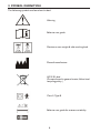
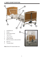
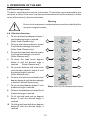
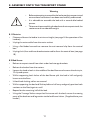
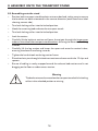
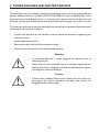
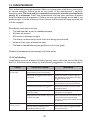
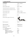
Community Care Bed Range
www.sidhil.com
User Instructions
CONTENTS
1. I NTRODUCTION
4
1.1 Features
4
1.2 Warnings & cautions
4
2. USE
5
2.1 Typical use
5
2.2 Risk assessment
5
2.3 Bed load
5
2.4 General warning
5
3. SYMBOL DEFINITION 6
4. PARTS IDENTIFICATION 7
5. BED ASSEMBLY AND PREPARING FOR USE 8
5.1 Removal from the transport stand 8
5.2 Assembling the bed 9
5.3 Fitting the electrical system 10
5.4 Stowing the transport stands 11
5.5 Checking the bed 11
6. OPERATION OF THE BED 12
6.1 General safety 12
6.2 Preparing for use 12
6.3 Brake system 13
6.4 Side rails 13
6.5 Mattress thickness 13
6.6 Electrical operation 14
6.6.1 Handset functions 14
6.6.2 Lockout function (SOLITE/UK/4 and SOLITE/UK/BB only) 15
6.7 Knee break / leg section 15
7. EXTENDING THE BED (all variants) 16
7.1 To extend the bed frame
16
7.2 To extend the platform 16
8. ASSEMBLY ONTO THE TRANSPORT STAND 17
8.1 Electrics 17
8.2 Bed frame 17
8.3 Assembling onto the stand 18
9. POWER FAILURES AND BATTERY BACKUP 19
10. LIFTING POLE (accessory)
20
11. DECONTAMINATION 21
12. MAINTENANCE 23
12.1 Fault finding 23
12.2 General maintenance 24
13. SPECIFICATION
25
13.1 Bed data
25
13.2 Electrical data 26
14. WARRANTY
27
3
1. INTRODUCTION
Thank you for purchasing this product. The user manual should be read carefully
before operating the bed. Please ensure that you understand all instructions, if you
have any questions concerning the operation or maintenance of the bed please contact
your provider/supplier who will provide you with expert professional advice.
1.1 Features
• Electrically operated backrest, height and knee break angle (only 4 section offers
full functionality).
• Infinitely variable electrically operated head and foot down tilt (Trendelenburg & reverse Trendelenburg).
• Auto-regressing backrest (not available on VH model).
• Integral leg extension.
• Auto contour – simultaneous adjustment of the backrest and knee break (not available on VH or 2 section models).
• Patient handset with individual function lockout (only 4 section beds).
• Bed breaks down into four separate sections.
• Transport stand to aid storage and bed transportation.
1.2 Warnings and cautions
Warnings in this user manual highlight potential hazards that if disregarded could lead
to injury or death.
Cautions in this user manual highlight potential hazards that if disregarded could lead
to equipment damage or failure.
4
2. USE
2.1 Typical use
Your bed is intended for use within the home environment. It has been designed to
provide users with optimum independence and freedom of movement through the use
of a touch button handset. The bed offers greatly reduced manual handling requirements
for the carer by providing a bed, depending on the model selected, with a fully profiling
platform and electrical height adjustment capability.
2.2 Risk assessment
Before a patient uses the bed a risk assessment must be performed on a patient by patient
basis. The risk assessment should include, but is not limited to:
• Entrapment
• Falling out of the bed
• Small children (and adults)
• Patients with learning difficulties
• Unauthorised people
Warning
Bed functions must be locked out if there is any doubt about the
ability of the patient to operate the bed safely. (Lockout functionality
only on 4 section beds.)
2.3 Bed load
The safe working load of the bed is: 222kg (35 stone)
The maximum user weight of the bed is: 190kg (30 stone)
2.4 General warning
Warning
• Misused electrical equipment can be hazardous.
• Accessories that have not been approved or designed for use
with the bed should not be used.
• Electrically operated beds should not be used in the presence of
flammable gasses.
5
3. SYMBOL DEFINITION
The following symbols are found on this bed:
Warning
Refer to user guide
Maximum user weight & safe working load
Place of manufacture
W.E.E.E Label
(Do not discard in general waste, follow local
recycling policy.)
Class II, Type B
Refer to user guide for matress suitability
6
4. PARTS IDENTIFICATION
1
8
7
2
5
4
3
1.
Head/foot end
2.
Castor
3.
Knee break actuator
4.
Leg section
5.
Locking collar
6.
Hi/low actuator
7.
Backrest actuator and control box
8.
Backrest
9. Transport Stand
9
Note: Solite UK 4 section bed shown
7
6
5. BED ASSEMBLY AND PREPARING FOR USE
Warning
• Before attempting to assemble the bed ensure these
instructions have been read and fully understood.
• It is advisable to assemble the bed with a second able bodied
person.
• Take care when disassembling the bed from the transport
stand, the sections are of considerable weight.
5.1 Removal from the transport stand
No tools are necessary for the assembly of the bed. The assembly procedure is as follows:
•
Clear the area intended for the bed of any obstructions and ensure the surface is level.
•
Apply the brakes to the castors.
•
Remove the clevis pin, r-clip and plastic spacer that goes through each transport stand and
holds the backrest in place (these parts will be required when assembling the bed sections
together) and then lift this section off the stand and carefully place flat on the floor.
•
Loosen the hand wheels on the leg section (attaching it to the transport stand) and then lift
this section off the stand and carefully place flat on the floor.
•
Turn the locking collars on one of the bed ends so that they are both in the unlocked
position, this is easily identified by a visible warning triangle.
•
Carefully lift the ends of the transport stand away from the bed end and place carefully
against a wall or on the floor. Note: when the transport stands are lifted away neither
bed end will be supported.
•
Turn the locking collars on the remaining bed end so that they are in the unlocked position.
•
Carefully lift the ends of the transport stand away from this bed end.
The bed has now been separated into its constituent parts.
Collar locked
8
Collar unlocked
5. BED ASSEMBLY AND PREPARING FOR USE
5.2 Assembling the bed
•
Whilst supporting one of the bed ends against
a wall, lift one of the mattress platform halves
and hook into the bed end. Turn the locking
collars into their locked position (warning
triangle not visible). Note: If this action is
being undertaken by a single person Sidhil
recommend that the castors are braked
before assembly commences.
•
Repeat for the remaining bed end and
mattress platform half.
•
Release the brakes on the castors.
•
Bring both halves of the bed together and
align each section so that the spigots in the
backrest section locate into the open tube
ends in the leg section. Pull the two sections
together and tighten the 2 hand wheels.
•
Place the clevis pins through the tube with
the head of the pin on the outside of the bed.
Place plastic spacer over the end of the pin
and insert the ‘R’ clips in from the top of the
bed through the hole in the pin.
Warning
•
The bed must never be used with the hand wheels loose or if missing.
•
The bed must never be used with the locking collars in the unlocked
position or if missing.
Caution
If the bed has been supplied with tie wraps/Velcro (or similar) securing
any of the sections in place ensure they are removed prior to operation.
9
5. BED ASSEMBLY AND PREPARING FOR USE
5.3 Fitting the electrical system
•
Plug the actuator and handset cables into the control box. The control box has a label
showing the correct port into which the corresponding cable is inserted. Note, the plugs
only fit into the ports in one orientation. Ensure the cables are plugged fully into the control
box.
Note: The two bed ends are identical however plugging them into the correct port is
important. Note the location of the correct end before plugging in.
•
Once all the cables are connected they are to
be secured in place by attaching the supplied
anti-removal clip.
•
Clip the mains cable into the clip on the head
end section of the bed (clip is secured by
twisting ends together).
•
Drive bed to maximum height then secure
actuator cables in the twist clips. Ensure each
bed end actuator cable has enough flex to
allow full movement of the actuator.
Mains cable clip
Backrest actuator
Knee break acuator
Foot end actuator
Head end actuator
Handset
Note: The image shows a SOLITE/UK/4 control box label.
Caution
• Ensure all cables are free from moving parts and are not under
excessive tension.
•
Ensure the two hi/low actuators are plugged into the correct ports,
if the tilt function is not functioning as expected the cables may have
been incorrectly located, double check against the diagram on the
controlbox.
10
5. BED ASSEMBLY AND PREPARING FOR USE
5.4 Stowing the transport stands
The bed comes complete with integral transport stand storage brackets.
• Raise the bed to its full height .
• Holding one transport stand turn it so the warning label is facing downwards.
• Slide the stand into the tubes positioned under the bullet backrest section, push
the spring clip down and push the stand past until the clip springs back locking the
transport stand in position.
• Repeat the procedure for the opposite side transport stand.
Spring clip
5.5 Checking the bed
The bed is now fully assembled. Before the bed is put into use ensure the bed is
correctly assembled:
• Are the locking collars on the corners of the bed correctly orientated in the locked
position (no visible warning triangles)?
• Are the 2 mattress platform and 4 extension hand-wheels tight?
• Has all packaging been removed, e.g. cable ties/Velcro, securing the platform
sections?
• Are the cables free of all moving parts of the bed and is there sufficient slack in the
cables to allow for movement?
• Is the bed clear of obstructions?
• Has a risk assessment been performed on the suitability of the bed for the user?
• Have the 2 clevis pins been passed through the bed’s central join and secured with
‘R’ clips?
11
6. OPERATION OF THE BED
6.1 General Safety
• When the bed is operated, ensure that obstacles such as over-bed tables and other
furniture are not causing an obstruction.
• Ensure the electrical cables are not in tension.
• Ensure that any mattresses used are of the correct size and type and have been
fitted correctly. A range of suitable pressure relieving and pressure reducing
mattresses are available from Sidhil Ltd.
• Before operating the bed ensure the patient is positioned appropriately.
• When a patient is left unattended ensure the bed is set at its minimum height.
Caution
Special care should be taken when fitting an air mattress to the bed as
incorrect fitting could damage the bed frame.
6.2 Preparing for use
Prior to operating the bed for the first time the following simple checks must be
performed:
• Ensure the bed and all accessories are at room temperature.
• Ensure the bed has been cleaned and disinfected (page 21).
• Ensure the mains cable is plugged into an appropriate mains socket.
• Ensure the brakes on the castors at the head end of the bed have been applied.
• Using the handset ensure the bed is level (see page 14 for handset operation).
Note: if the electrical functions do not operate ensure the handset has been ‘unlocked’
(see page 14 for handset operation) - not applicable to VH or 2 section beds.
12
6. OPERATION OF THE BED
6.3 Brake system
The bed has 4 braked castors.
• To apply the brakes: Press the brake pedal down.
• To release the brakes: Lift the brake pedal up.
When the bed is in use ensure the brakes on the castors at the head end of the bed
have been applied.
Warning
• If the bed is to be pushed up/down a slope it is advised that two
people move the bed, with one person at each end.
• If the bed is to be pushed with a heavy load it should be assessed
whether or not two people should move the bed, this is
dependent on the situation and load on the bed.
6.4 Side rails
The SOLITE UK bed range can be specified with four different types of side rail
(Cantilever 3 & 4 side rails, Solite safe side and Savile trombone style side rails), this is to
provide the optimum mattress/side rail combination for both foam and air mattresses
of varying thicknesses. When specifying a mattress and side rail combination a clinical
assessment of the patient’s needs must be carried out in line with the local policy.
6.5 Mattress thicknesses
If an overlay air mattress is used it may be necessary to use a thinner foam mattress for
the combined height to maintain the 270mm dimension.
Refer to MHRA Device Bulletin DB2006 (06) ‘Safe use of bed rails’.
Side rails pose a potential entrapment hazard, please refer to the side rail
safety notice, SR/PSN 01/01/1, supplied with this product.
Standard, 3 bar, cantilever side rail = 158mm maximum mattress thickness
High, 4 bar, cantilever side rail = 270mm maximum mattress thickness
Caution
Do not use the side rails to move the bed.
13
6. OPERATION OF THE BED
6.6 Electrical operation
The bed is supplied with an easy-to-use handset. The handset may be operated by the
occupant or carer. If the carer is to operate the bed ensure that the occupant is made
aware of the action(s) about to take place.
Warning
Ensure a risk assessment is undertaken to ensure the suitability of the
occupant using the handset.
6.6.1 Handset functions
1. To raise the backrest depress button 1
until the desired angle is reached. (Solite 2 and 4 Section only.)
1
2
2.
To lower the backrest depress button
2 until the desired angle is reached.
(Solite 2 and 4 Section only.)
3
4
3.
To raise the knee break depress button
3 until the desired angle is reached. (Solite 4 Section only.)
5
6
7
8
9
10
4. To lower the knee break depress
button 4 until the desired angle is
reached. (Solite 4 Section only.)
5. To raise the backrest and knee break
(auto contour) depress button 5 until
the desired angle is reached.
(Solite 4 Section only.)
6. To lower the backrest and knee break
depress button 6 until the desired angle
is reached. (Solite 4 Section only.)
7. To raise the bed depress button 7 until
the desired angle is reached.
Note: SOLITE/UK/4 handset label shown
8. To lower the bed depress button 8 until
the desired angle is reached.
9. To tilt the bed head end up depress
button 9 until the desired height is
reached.
10. To tilt the bed head end down depress
button10 until the desired height is
reached.
14
6. OPERATION OF THE BED
6.6.2 Lockout function (SOLITE/UK/4 and SOLITE/UK/4/BB only)
The handset is supplied with a lockout function which enables the carer to disable any
of the bed’s functions if they are deemed unsuitable for the occupant.
To lock/unlock a function, turn the relevant function lock using the key provided
(clockwise to lock, anti - clockwise to unlock). When a function has been locked a
yellow dot will be visible above that function.
Locked
6.7 Knee break/leg section
Note: The operation of the knee break/leg section is dependent on the position of the
support bow as detailed below.
The bed is fitted with an adjustable leg section. When the knee break function on the
handset is operated the height or angle of the leg section is adjusted, depending on
whether or not the leg support is located in the channel on the underside of the leg
section.
Knee break height/angle adjustment:
Leg section height adjustment:
Leg section
Support bow
To set the bed so that the knee break is raised:
• Press the knee break button on the handset and raise the leg section (height not
important).
• Lift the leg section a little so that the support bow releases from the channel and
rests on the supporting tube.
• Gently lower the leg section down.
• The knee break angle will now become more acute as the knee is driven up.
To set the bed so that the leg section is raised:
• Press the knee break button on the handset and raise the knee break (height not
important).
• Lift the leg section a little so that the support bow located under the leg section can
be lifted and located into the channel on the leg section.
• The leg section will now raise parallel to the bed frame as the knee break is driven
up.
15
7. EXTENDING THE BED (all variants)
7.1 To extend the bed frame
• Flatten and lower the bed to its minimum
height (see page 14 for operation of the
handset).
Bedframe hand wheels
• Apply the brakes to the head end of the bed.
• Unclip the foot end actuator cable from
the bed frame cable clip (to prevent over
extending the cable).
• Loosen the four hand wheels at the foot end
of the bed (2 per side).
• Unlock the foot end castors whilst holding the
foot end near the locking collars pull the bed
extension out until it reaches the end stops.
• Re-tighten all the hand wheels and secure the
actuator cable back into its clip.
7.2 To extend the platform
• Loosen by 3 - 4 turns the two hand wheels
located on the platform section.
Platform hand wheel
• Slide the platform extension out to the correct
length to suit the mattress and extension block
being used (if a Sidhil mattress and extension
are being used then it may be pulled out to the
end stops).
• Re-tighten the extension hand wheels (take
care not to over tighten as damage to the
extension tubes may occur).
7.3 Returning the bed to its original state is a reverse of the above.
Warning
The platform extension must be returned to its shortened length
before reducing the main bed frame extension or severe damage
could be caused to the platform extension.
16
8. ASSEMBLY ONTO THE TRANSPORT STAND
Warning
• Before attempting to assemble the bed onto the transport stand
ensure these instructions have been read and fully understood.
• It is advisable to assemble the bed with a second able bodied
person.
• Take care when assembling the bed onto the transport stand, the
sections are of considerable weight.
8.1 Electrics
• Flatten and lower the bed to its minimum height (see page 14 for operation of the
handset).
• Unplug the mains cable from the mains socket.
• Using a flat bladed screwdriver remove the anti-removal clip from the control
box.
• Unplug the hi/low and knee break actuator cables from the control box (see page
10).
8.2 Bed frame
• Release transport stands from their under bed storage brackets.
• Release the brakes from the castors.
• Loosen the hand wheels in the middle of the bed frame and remove the clevis pin,
‘R’ clip and spacer.
• Whilst supporting both halves of the bed frame split the bed in half and gently
lower onto the floor.
• Unlock both locking collars on one end.
• Whilst supporting the bed end lift the platform half away and gently position both
sections on the floor/against a wall.
• Repeat for the remaining half of the bed.
• Using the 2 orange Velcro straps that first came with the bed, secure the moving
parts of the backrest and leg section to the bed frame halves. (If applicable to your
model.)
17
8. ASSEMBLY ONTO THE TRANSPORT STAND
8.3 Assembling onto the stand
• Position both transport stand brackets onto one bed end, taking care to ensure
the brackets are both orientated in the correct direction (each stand has a label
showing correct side).
• Turn both locking collars into the locked position.
• Hook the remaining bed end onto the transport stands.
• Turn both locking collars into the locked position.
• Lock the castors.
• Carefully lift the backrest section and lower the spigots through the larger open
tubes on the side of the transport stand brackets, ensuring the electrics are facing
inwards.
• Carefully lift the leg section and lower the open end onto the vertical tubes,
ensuring the electrics are facing inwards.
• Tighten the hand wheels on the leg section frame.
• Place the clevis pins through the backrest section and secure with the ‘R’ clips and
spacers.
• Ensure all cabling is neatly wrapped around the relevant bed sections and is not
dragging on the floor or under excess tension.
Warning
The bed must never be moved on the transport stand with the locking
collars in the unlocked position or missing.
18
9. POWER FAILURES AND BATTERY BACKUP
The bed does not have battery backup functionality unless you have purchased the
battery backup variant of the bed (SOLITE/UK/4/BB) this can be identified by a box
fastened to the knee break motor. In the event of a power failure the bed will not
function, resulting in the backrest and/or knee break remaining up, if previously raised.
The backrest and knee break are operated via two individual actuators that are located
underneath the mattress platform.
• If either the backrest or knee break is raised, locate the actuator supporting the
relevant section.
• Hold/support the section.
• Remove the pins that hold the actuator in place.
• Gently lower the section(s) to the flattened position.
Warning
• It is recommend that 2 carers support the section prior to
removing the pin.
• When the pins are removed there is nothing supporting the
section, the carer(s) holding the frame must be ready to support
the weight on removal of the pin.
Caution
• If fitted with a Battery Backup this should only be used in an
emergency for normal operation the bed must always be
plugged into the mains supply.
19
10. LIFTING POLE (accessory)
The patient lifting pole is supplied complete with strap and handle.
Warning
The maximum supporting weight of the pole is 80kg (12.5 stone)
The lifting pole is inserted into one of the two sockets located in the corners of the
backrest section of the bed. Ensure that the pin located in the lifting pole fits into the
slot in the socket. Once inserted make sure that the lifting pole is stable and cannot
rotate.
Sidhil Ltd recommends frequent checking of an attached lifting pole. This should
include looking for any signs of damage, loose stitching, fraying or any other material
degradation. If evidence of any of the above is apparent, replace the strap and handle
or the entire lifting pole assembly immediately.
20
11. DECONTAMINATION
Infection control and routine cleaning must be carried out in accordance with your
local Infection control policy or regulatory body.
Your bed comes with an antibacterial additive incorporated into
the powder coated metalwork. Biocote® inhibits the growth of
bacteria on the surface of the bed frame. It is effective against a wide
range of both gram positive and negative bacteria as well as fungi.
Examples of bacteria that Biocote® is resistant to include:
• Bacillus Subtilis
• Staphylococcus Aureus (MRSA)
• Escerichia Coli 0157
• Streptococcus Faecalis
• Salmonella Enteritides
• Listeria Monocytogenes
Warning
Biocote is an aid to keeping your bed infection free but it does not
substitute the need for the bed to be cleaned at regular intervals.
®
21
11. DECONTAMINATION
Warning
Always disconnect the bed from the main power supply prior to
cleaning.
It is advisable to remove any accessories that are fastened to the bed.
These instructions apply to all accessories apart from soft products (e.g. mattresses).
• All surfaces to be wiped down with a disposable soft cloth moistened with a mild
detergent and diluted in warm water (40°C).
• The bed should be cleaned by starting with the cleanest parts of the bed and
systematically moving to the dirtiest parts. Extra care should be taken around
areas where excess dirt or dust may gather.
• The cloth should be changed during the cleaning process if it becomes soiled.
• Rinse down with clean water to remove detergent residue.
• Wipe surfaces down with 1,000 parts per million chlorine solution (0.1%).
• Dry off with a paper towel.
• Always ensure the cleaned parts are allowed to dry before putting the mattress
back in place.
Note: If any of the 3 stages stated above (detergent, rinse down & chlorine solution)
are omitted or combined it will reduce the effectiveness of the clean.
In cases of blood spills or other bodily fluids it is recommended that a chlorine solution
of 10,000 parts per million (1%) is used instead.
Note: The use of neat bleach or similar surface cleaners are not recommended as
damage may be caused to the cleaned surfaces.
Alternatively:
Sidhil recommend the use of Chlor-clean tablets. Follow the manufacturer’s
instructions for concentration guidelines and instructions for use.
Refer to the Sidhil infection control policy, copies are available from Sidhil Ltd. Contact
details can be found on the back of this booklet.
22
12. MAINTENANCE
Only authorised service personnel or Sidhil service engineers should carry out repairs
or service activities. Failure to do so may result in the manufacturer’s warranty
becoming void. The bed and its associated accessories must be serviced once
yearly, as a minimum. Sidhil also recommends that the carer performs frequent
visual and operational inspections. If there are any signs of damage or the bed is not
performing as it should withdraw it from service until the bed has been repaired and
is fit for use again.
Periodically check to ensure that:
• The bed operates as per its intended purpose.
• All parts are present.
• All fixtures and fittings are tight.
• The frame is mechanically sound, with no cracking around welds.
• No parts show signs of excessive wear.
• The bed is cleaned following the guidelines in this user guide.
Disposal of components must comply with local policy.
12.1 Fault finding
Listed below are a set of electrical faults that may occur within the service life of the
bed. If a fault does occur please try the following suggestions, as these may help in
Fault
Electrical function(s)
do not work
Electrical functions
working slowly
Possible Cause
Remedy
Functions locked out on handset
(Not on Solite VH or 2 section beds)
Unlock function(s)
Mains lead not plugged into the control
box or wall
Check to see if the ‘power on’ light on
the control box is lit and the mains lead is
plugged in at both ends
Fuse has blown in the mains plug
Check to see if the ‘power on’ light on
the control box is lit, if not replace fuse
Actuator/handset leads not plugged in
Check plug connections on the control
box and actuators
Damage to mains cable, actuator cable
or handset cables
Turn off at the mains and contact an
approved service engineer
Heavy load on the bed and the duty cycle
has been exceeded
If the control box has exceeded its duty
cycle permanent damage will have
occurred, a replacement control box will
be required
Heavy load on the bed
Remove load
Bed is operating on battery power
(Solite Battery Backup only)
Check mains cable is plugged in at both
ends and turned on
23
12. MAINTENANCE
12.2 General maintenance
Sidhil recommend that the following maintenance procedure is performed every 12
months.
Warning
Always disconnect the bed from the main power supply and battery
backup prior to performing any maintenance procedures.
• Check that all electrical functions operate correctly on the handset.
• Check that all electrical cables are in good condition.
• Check that the mains cable and plug are in good condition, if either is damaged it
must be replaced as a complete assembly, the plug must never be re-wired.
• Check that all nuts, bolts and fasteners are tight and that none are missing or
incomplete.
• Check that all locking collars and hand wheels are present.
• Check that both the knee break and leg rest functions work correctly.
• Check the castors lock/unlock correctly and that when locked the castors do not
swivel or roll.
• Check that the frame is mechanically sound with no cracking at welds etc.
• Check the extension capability.
• Check backrest sliders for wear/degredation.
For more detailed service information please contact Sidhil Ltd.
24
13. SPECIFICATION
13.1 Bed data
Overall length
2250mm - 2395mm
Overall width
970mm
Mattress platform height
300mm – 705mm
Under bed clearance (to underside of frame)
250mm
Under bed clearance (to underside of actuator)
105mm
Mattress platform length
2000mm - 2145mm
Mattress platform width
927mm (suits 880mm mattress)
Head down tilt
0 - 11°
Foot down tilt
0 - 11°
Mattress platform angles of 4 section bed
70°
13°
Backrest regression
100mm
Safe working load
222kg (35 stone)
Maximum user weight
191kg (30 stone)
Product weight:
(On transport stand): Individual Item weight
Backrest
Backrest (non profiling)
Leg Section (with knee break)
Leg Section (non profiling)
Bed End
25
75kg
19.5kg
12kg
19kg
11kg
17kg
24°
13. SPECIFICATION
13.2 Electrical data
Voltage in
240V, ~50/60Hz
Current in
Max. 1A
Duty rating
10%
Max 2/18min.
Safety standards
BS EN 60601-1: 2006
BS EN 60601-2-52:2010
EMC
BS EN 60601-1-2:2002
Electrical shock protection
Liquid ingress protection
IP54
The electrical system is only suitable for use when:
Ambient temperature
+5° to +40°C
Humidity
20% - 90% at 30°C
26
14. WARRANTY
Sidhil Ltd guarantees this product is free from defects in material and workmanship under
normal use for 5 years (1 year full for parts and labour, 4 further years for parts only) from
the date of purchase from Sidhil Ltd and its subsidiary companies or its authorised dealers.
All implied warranties, including but not limited to those implied warranties of fitness and
merchantability, are limited in the total duration of one year from date of purchase. Proof of
purchase must be presented with any claim. Except as provided herein, Sidhil Ltd, product
warranty does not cover damage caused by misuse or abuse, accident, the attachment of
any unauthorised accessory, alteration to the product, or any other conditions whatsoever
that are beyond the control of Sidhil Ltd. Sidhil Ltd and its subsidiary companies shall have
no liability or responsibility to customer or any other person or entity with respect to any
liability, loss or damage caused direct or indirectly by use or performance of the product or
arising out of any breach of this warranty, including but not limited to any damages resulting
from inconvenience, loss of time, property, revenue, or profit or any indirect, special,
incidental or consequential damages, even if Sidhil Ltd or their subsidiary companies or
authorised dealers has been advised of the possibility of such damages.
In the event of a product defect during the warranty period you should contact Sidhil
Ltd or their authorised dealer who will at its option unless otherwise provided by law; a)
correct the defect by product repair without charge for parts and labour b) replace the
product with one of the same or similar design or c) refund the purchase price. All replaced
parts and products on which refund is made become the property of Sidhil Ltd. New or
reconditioned parts and products may be used in the performance of warranty service.
Repaired or replaced parts and products are warranted for the remainder of the original
warranty period. You will be charged for repair or replacement of the product made after
the expiration of the warranty period.
This warranty does not cover; a) damage or failure by or attributes to acts of God, abuse,
accident, misuse, improper or abnormal usage, failure to follow instructions, improper
installation or maintenance, alterations, lightning or other incidence of excess voltage or
current, b) any repairs other than those provided by a Sidhil Ltd authorised technician, c)
consumables such as fuses, d) cosmetic damage, e) transportation, shipping or insurance
costs or f) costs of product removal, installation setup service adjustment or re-installation.
This limited 5 year warranty gives you specific legal rights and you may also have other
rights.
Sidhil Ltd cannot be held responsible for any injury or incident which relates to the use of
this bed in conjunction with accessories manufactured by companies other than Sidhil Ltd.
All products carry the CE mark in accordance with EC Directive on Medical Devices
(93/42/EEC).
Sidhil has a policy of continual product improvement and reserves the right to amend
specifications covered in this brochure.
No part of this brochure may be reproduced without the written approval of Sidhil Ltd.
27
CONTACT INFORMATION
Tel: 01422 233000 Fax: 01422 233010
Email: [email protected] www.sidhil.com
Sidhil Business Park, Holmfield, Halifax, HX2 9TN
A member of the Siddall & Hilton Ltd. Group of Companies
(93/42/EEC)
Certificate No. FM14550
INSTRUC/SOLITE/UK, 9/11/11 - rev1