1
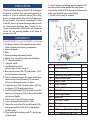
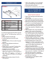
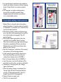
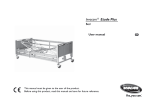
lifetime limited
warranty
Your Drive brand product is warranted to be free
of defects in materials and workmanship for the
lifetime of the original consumer purchaser.
This device was built to exacting standards and
carefully inspected prior to shipment. This Lifetime
Limited Warranty is an expression of our confidence in the materials and workmanship of our
products and our assurance to the consumer of
years of dependable service.
In the event of a defect covered by this
warranty, we will, at our option, repair or replace
the device.
This warranty does not cover device failure
due to owner misuse or negligence, or normal
wear and tear. The warranty does not extend to
non-durable components, such as rubber
accessories, casters, and grips, which are subject
to normal wear and need periodic replacement.
If you have a question about your Drive device or
this warranty, please contact an authorized Drive
dealer.
© 2005 Medical Depot, Inc. All rights reserved.
Drive is a trademark of Medical Depot, Inc.
Port Washington N.Y. 11050 USA Made in China
electric patient lift
item #13240
instructions
The Drive Deluxe Electric Patient Lift is designed
to transfer a patient from one resting position to
another. It is not a transport device. Use a sling
that is recommended by the individual’s physician.
During transfer, with patient suspended in a sling
to the lift, do not roll caster base over objects such
as raised carpet bindings, door frames, or any
uneven surfaces that would create an imbalance
of the lift. Use steering handles at all times to
maneuver the lift.
H. Insert the base spreading adjusting handle (#3)
into the socket located behind the mast sleeve.
I. Attach the cradle (#11) to the end of the boom and
make sure the bolts are screwed tightly.
J. The lift is now ready to operate.
Figure 1
installation
Follow Figure 1 (on right) & Figure 2 (on next page)
1 The Electric Patient Lift is packed in one carton
which contains the following components:
A. Mast with boom
B. Base.
C. Base spreading adjustment handle.
D. Battery box, control box and control handset.
E. “C” shaped push bars
F. 4/6 point cradle
2 Installation Procedure:
(please refer to chart on pg.3)
A. Remove the screws (#16, #17) and washer (#20)
from the base as indicated.
B. With the boom pointed in the same direction as
the base legs, insert the mast (#2) into mast sleeve and ensure the mast is in place.
C. Install the screw (#16, #17) and washer (#20) on to the mast (#2) through mast sleeve.
D. Install the push handles (#14,#15) into the mast (#2) and ensure the screws (#19) on the push handles are screwed tightly.
3 Please refer to the following pictures:
E. Unscrew the gold colored screw (#18)
F. Mount the control box (#4) on the bracket (#9)
and screw back the bolts (#18) on the bottom of the bracket.
G. Place and clip the battery pack (#7) on the top
of the bracket.
Part# Description
1
2
3
4
5
6
7
8
9
10
11
12
13
14
15
Base Assembly
Mast
Spreading Adjustment Handle
Linak Control Box
Power Cord
Linak Acuator
Battery Pack
Fitted Screws
Mounting Bracket
Hand Set
4/6 Point Cradle
Boom
Fixed Screw
“C” Shaped Push Bar - Right
“C” Shaped Push Bar - Left
Qty
1
1
1
1
1
1
1
2
1
1
1
1
2
1
1
1. Where mast and boom connect, hanging bar
hook, pump handle hinge, and caster axles.
2. Where pump and boom attach.
3. Lubricate above mentioned every 2 to 3 months.
installation cont.
Figure 2
how to operate the
electric patient lift:
Part# Description
16
17
18
19
20
Hexagon Screw - M12x35
Hexagon Screw - M12x30
Screw - M6x10
Fixed Screw
Washer
Qty
1
1
1
1
1
➝
It is extremely important that the lift be inspected before each use. The following items need to be
checked:
a. All nuts and bolts should be tight.
b. The lifter should move freely with caster
brakes off.
c. Check the brakes on the rear casters for proper operation.
d. Make sure base adjustment mechanism is
operating easily.
e. Double check to ensure the “U” bracket at the
end of the boom and the “S” hook on the
hanging bar are secured tightly.
f. Work the Linak Actuator to ensure that the battery has enough power. When the battery is
50% below full capacity, it will give a
“beep” warning and will need to be re-charged
immediately.
g. Before initial use, place a drop of oil on the
following areas:
weight capacity: 450 lbs.
1. Spread the base legs to the widest position
before lifting.
2. Keep the patient centered between the base
legs and have the patient face the attendant.
3. Be extremely cautious and use restraint straps
for spastic or severely handicapped patients.
4. How to use Standard or Commode Slings.
a. For smooth and easy lifting, have the lift,
chains, sling, commode or wheelchair in ready
position.
b. With the patient in the center of the bed, roll patient on side away from the attendant.
c. Roll the patient on side toward the attendant
and center the patient on sling. With the base
of lifter under bed, press the down button on
the control handset to lower the boom.
d. With base of lifter under bed press “ “ button
on the control handset to lower the boom (#20)
e. Hook the hanging strips of sling with the hanging bar. If a chain is used, make sure the “S” hooks are away from the patient. Lock rear
casters, lift the patient by pressing the up
button on the control handset.
f. Lift patient until his/her feet will swing easily
off the bed keeping patient facing the attendant.
g. Unlock rear casters and transfer patient to and
above commode or wheelchair. Lock brakes of
both lifter and commode (or wheelchair).
h. Press the down button on control handset to
gradually lower the patient.
i. During the descent, assist patient to attain
correct sitting posture.
j. For transferring to wheelchair, when patient is
seated, push down on boom to slacken hanging
strips of sling. Patient can remain seated in sling.
k. For commode use, adjust clothing before moving lift to straddle commode. Keep hanging strips taut and make sure patient
is in a comfortable position.
Figure 3
QUICK
RELEASE
Hand control
INSTALLATION
B
A
important safety instructions:
1. Patient lifter is a transfer device that allows
patient attendant to transfer patients from bed
to wheelchair or commode...etc. It should not be
used to transport patients.
2. When lifting patient, make sure the base legs
are in the most widely opened position and the rear caster brakes are engaged. This will
prevent tipping.
3. When battery power goes below 50%, the
controller has an audible “beep” warning.
When the low battery warning is heard, charge
the battery immediately. Please note that a
lifted patient cannot be lowered down when
battery is out of power.
4. Push the “emergency” red button if the control
unit system is not functioning properly.
5. In the event of a power failure, a person can be lowered by pulling up on the red quick release lever. (please refer to figure 3)
6. How to charge: (please refer to figure 4)
a. Insert the power cord into the bottom of the control box and the other end into a wall outlet.
b. The battery is charging when the “charge”
light is illuminated.
c. When the battery charge is completed, the
“charge” light will shut off automatically (on
average, it takes approximately 4 hours to
charge from 50% to 100% capacity).
d. Remove the power supply cord.
e. The lift is now operational.
Align the plug guide line (A),
with the receptacle guide line (B).
Once they are aligned,
connect them together.
Figure 4