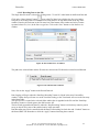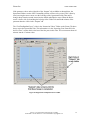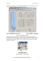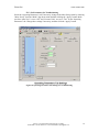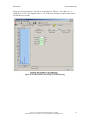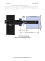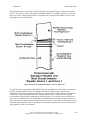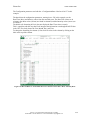
1
Instruction Manual
Extorr XT Series RGA
Models XT100(M), XT200(M), XT300(M)
using VacuumPlus Software Version 1.0.40 and above
Rev 150928 by Extorr, Inc. 2015
Extorr Inc.
www.extorr.com
Table of Contents
1. Safety Information ................................................................................................... 6
2. Overview ................................................................................................................... 7
2.1. General Description ................................................................................................................ 7
3. Dimensions and Specifications ................................................................................ 8
3.1. Dimensions ............................................................................................................................... 8
3.2. Specifications ........................................................................................................................... 9
4. Installation .............................................................................................................. 10
4.1. Unpack the XT Shipment ..................................................................................................... 10
4.2. Factors to Consider before Mounting the Probe ............................................................... 10
4.3. Mount the Probe ................................................................................................................... 11
4.4. Connect the Command and Control Unit (CCU) .............................................................. 12
4.5. Attach the RS232 Cable and Power the Unit ..................................................................... 12
4.6. Install the VacuumPlus Software ........................................................................................ 12
4.7. Resonating RF Coil ............................................................................................................... 12
4.8. Start Pump Down .................................................................................................................. 13
5. Operation ................................................................................................................ 14
5.1. General theory of Operation ................................................................................................ 14
5.2. Pirani Readout ...................................................................................................................... 14
5.3. Ion Gauge Readout ............................................................................................................... 15
5.4. Filament Activation Switch .................................................................................................. 15
5.5. Reading Mass Peak Heights ................................................................................................. 15
6. VacuumPlus Software ........................................................................................... 16
6.1. Starting-up ............................................................................................................................. 16
6.2. GUI ......................................................................................................................................... 17
6.3. Operational Settings ............................................................................................................. 17
6.4. Communications Tab ........................................................................................................... 18
6.5. Configuration Tab ................................................................................................................ 19
6.6. Sweep Parameters Tab ......................................................................................................... 19
Extorr Inc., 307 Columbia Road, New Kensington, PA 15068
TELEPHONE: 1-724-337-3000 FAX: 1-724-337-8322 EMAIL: [email protected]
2
Extorr Inc.
www.extorr.com
6.7. Operating Parameters Tab .................................................................................................. 21
6.7.1. Mode ............................................................................................................................................................. 21
6.7.2. Focus ............................................................................................................................................................. 21
6.7.3. Electron Energy and Emission current .......................................................................................................... 21
6.7.4. Electron Multiplier ........................................................................................................................................ 22
6.7.5. AutoZero ....................................................................................................................................................... 22
6.7.6. Pressure Units ............................................................................................................................................... 22
6.7.7. Filament Control ........................................................................................................................................... 22
6.8. Calibration Parameters Tab ................................................................................................ 23
6.8.1. Low Cal and High Cal ................................................................................................................................... 23
6.8.2. Unit Information............................................................................................................................................ 23
6.8.3. Pirani Calibration .......................................................................................................................................... 24
6.8.4. Total and Partial Integrating Caps ................................................................................................................. 24
6.8.5. Total and Partial Sensitivity .......................................................................................................................... 24
6.8.6. Diagnostics .................................................................................................................................................... 24
6.9. Mass Table Tab ..................................................................................................................... 24
6.9.1. Mass Table Setup for Leak Detection ........................................................................................................... 26
6.10. Outputs Tab......................................................................................................................... 28
6.11. Plot Tab ................................................................................................................................ 29
6.12. Print Tab .............................................................................................................................. 29
6.13. Log Tab ................................................................................................................................ 30
6.14. Record Data Tab ................................................................................................................. 31
6.14.1. Recording Data Off ..................................................................................................................................... 31
6.14.2. Recording Data to One File ......................................................................................................................... 32
6.14.3. Recording Data to Multiple Files ................................................................................................................ 33
6.14.3.1. Recording Data to Multiple Files Once Per Scan Option .................................................................... 34
6.14.3.2. Recording Data to Multiple Files On The Hour Option ...................................................................... 35
6.14.3.3. Recording Data to Multiple Files At Midnight Option ........................................................................ 35
6.14.3.4. Recording Data to Multiple Files After N Sweeps Option .................................................................. 36
6.15. Diagnostics Tab ................................................................................................................... 36
6.16. XML Use .............................................................................................................................. 37
6.17. Use with Multiple XT Systems ........................................................................................... 39
6.18. The Degas Mode .................................................................................................................. 39
6.19. Graph Window .................................................................................................................... 40
6.19.1. Graph Window Slider Controls ................................................................................................................... 40
6.19.2. Changing the Relative Size of the Graph Window and Folder Tabs ........................................................... 46
6.19.3. Graph Window Zoom and Undo Zoom ...................................................................................................... 48
6.19.4. Mass Sweep or Mass Table Customization Menu ...................................................................................... 51
7. Maintenance ........................................................................................................... 52
7.1 Servicing the RGA probe ...................................................................................................... 52
7.1.1. Ionizer /Dual Filament Replacement ............................................................................................................. 52
Extorr Inc., 307 Columbia Road, New Kensington, PA 15068
TELEPHONE: 1-724-337-3000 FAX: 1-724-337-8322 EMAIL: [email protected]
3
Extorr Inc.
www.extorr.com
8. Return Procedure................................................................................................... 56
Appendix A. First Mass Spectrum ........................................................................... 57
Appendix B. Gauge Sensitivity to Differing Gases ................................................. 60
B.1. Pirani Gauge ......................................................................................................................... 60
B.2. Ion Gauge Corrections ......................................................................................................... 60
B.3. Determination of Partial Pressures .................................................................................... 61
Appendix C. Manual Tuning of an RGA................................................................. 63
Appendix D. Options and Spare Parts ..................................................................... 66
Appendix E. Troubleshooting and Service .............................................................. 70
E.1. Troubleshooting.................................................................................................................... 70
E.1.1. Switch to a Known Good Configuration File ............................................................................................... 70
E.1.2. Configure VacuumPlus for Troubleshooting ................................................................................................ 70
E.1.3. Set Parameters for Troubleshooting.............................................................................................................. 74
E.1.4. Examine Output Tab Parameter Values ........................................................................................................ 76
E.1.5. Creating Screen Captures.............................................................................................................................. 78
E.2.1. Normal Operation ......................................................................................................................................... 80
E.2.2. Filaments Open (Burned Out) ....................................................................................................................... 81
E.2.3 Source 1 Shorted to Vacuum Chamber (Ground) .......................................................................................... 82
E.2.4. Source 2 Shorted to Vacuum Chamber (Ground) ......................................................................................... 83
E.2.5. Focus 1 Shorted to Vacuum Chamber (Ground) .......................................................................................... 84
E.2.6. Repeller Shorted to Vacuum Chamber (Ground) ......................................................................................... 85
E.2.7. Filaments Shorted to Vacuum Chamber (Ground) ....................................................................................... 86
E.2.8. Filaments Shorted to Source 1 ...................................................................................................................... 87
E.2.9. Repeller Shorted to Source 1 ........................................................................................................................ 88
E.2.10. Repeller, Source 1, and Focus 1 Shorted Together ..................................................................................... 89
E.2.11. Focus 1 Shorted to Source 1 ....................................................................................................................... 90
E.3. Outputs Tab Parameter Definitions ................................................................................... 91
E.3.1. Reference ...................................................................................................................................................... 91
E.3.2. Ground Ref ................................................................................................................................................... 91
E.3.3. Degas Current ............................................................................................................................................... 91
E.3.4. Electronics Temperature ............................................................................................................................... 91
E.3.5. Power Supply ................................................................................................................................................ 92
E.3.6. Filament Voltage .......................................................................................................................................... 92
E.3.7. Filament Resistance ...................................................................................................................................... 92
E.3.8. Sensor Temperature ...................................................................................................................................... 92
E.3.9. Source 1 Current ........................................................................................................................................... 93
E.3.10. Source 2 Current ......................................................................................................................................... 93
E.3.11. RF Amp ...................................................................................................................................................... 93
E.3.12. Pirani Temp ................................................................................................................................................ 94
E.3.13. Pirani Corr .................................................................................................................................................. 94
E.3.14. Pirani Press ................................................................................................................................................. 94
E.3.15. +FB ............................................................................................................................................................. 94
E.3.16. -FB .............................................................................................................................................................. 94
E.3.17. Focus 1 FB .................................................................................................................................................. 94
E.3.18. Repeller ....................................................................................................................................................... 94
Extorr Inc., 307 Columbia Road, New Kensington, PA 15068
TELEPHONE: 1-724-337-3000 FAX: 1-724-337-8322 EMAIL: [email protected]
4
Extorr Inc.
www.extorr.com
E.3.19. Filament Power: .......................................................................................................................................... 95
E.3.20. Filament DAC Coarse ................................................................................................................................. 95
E.3.21. Filament DAC Fine ..................................................................................................................................... 95
E.4. Vacuum Probe Mounting Considerations to Avoid Electrical Short Circuits ............... 96
E.4.1. Preferred Probe Mounting Arrangement ...................................................................................................... 97
E.4.2. Mounting the Probe Using a Vacuum Nipple ............................................................................................... 98
E.5. Finding Electrical Short Circuits Caused by Damage to the Probe .............................. 101
Appendix F. Electron Multiplier Installation........................................................ 106
F.1. Unpack the Shipment ......................................................................................................... 106
F.2. Preparation ......................................................................................................................... 106
F.3. Install Electron Multiplier ................................................................................................. 107
F.4. Install High Voltage Power Supply Module ..................................................................... 109
Appendix G. COM Port Troubleshooting ............................................................. 111
G.1. Connecting the USB to RS232 Converter ........................................................................ 111
G.2. Installing the USB to RS232 Converter Driver Software .............................................. 111
G.3. Identifying the COM Number of the USB to RS232 Converter .................................... 112
G.4. Changing the COM Number of the USB to RS232 Converter ...................................... 116
G.4.1. Device Manager Shows All Ports In Use ................................................................................................... 123
Appendix H. Analyzing Recorded Data In Microsoft Excel ................................ 130
H.1. Data Saved to a Single File in the Mass Sweep Mode..................................................... 130
H.2. Data Saved to Multiple Files Once Per Scan in the Mass Sweep Mode ........................ 142
H.3. Data Saved to a Single File in the Trend Mode ............................................................... 152
H.4. Data Saved to Multiple Files Once Per Scan in the Trend Mode .................................. 173
Appendix I. Filament Trip Diagnosis ..................................................................... 193
Appendix J. High Pressure Operation ................................................................... 195
Appendix K. Integrating Capacitor Causing Very Noisy Baseline ..................... 196
Appendix L. Pirani Gauge Will Not Allow Filament to Turn On ....................... 198
Warranty................................................................................................................... 202
Extorr Inc., 307 Columbia Road, New Kensington, PA 15068
TELEPHONE: 1-724-337-3000 FAX: 1-724-337-8322 EMAIL: [email protected]
5
Extorr Inc.
www.extorr.com
1. Safety Information
Limitation on use of Compression Mounts
WARNING!
Do not use a compression mount (quick-connect) for attaching the Analyzer
probe to the vacuum system in applications that may develop positive pressures.
Positive pressures may cause the probe to be blown out of a compression fitting
and damage equipment and injure personnel.
Extorr Inc., 307 Columbia Road, New Kensington, PA 15068
TELEPHONE: 1-724-337-3000 FAX: 1-724-337-8322 EMAIL: [email protected]
6
Extorr Inc.
www.extorr.com
2. Overview
2.1. General Description
The Extorr XT Series instruments are quadrupole residual gas analyzers which also include an enhanced
Pirani gauge as well as a hot cathode ion gauge. The Pirani gauge makes vacuum measurements based on
thermal conductivity of the gas environment. The ion gauge uses electron impact ionization of residual gases
to measure ion currents related to pressure. The quadrupole gas analyzer uses precision mechanics and
electronics to measure ion currents due to the partial pressures of the residual gases in the vacuum chamber.
The Pirani starts operation at atmospheric pressure, the ion gauge at a nominal 10-2 torr and the quadrupole
starts at a nominal 10-4 torr pressure. The ion gauge will measure total pressures to its x-ray limit of 2x10⁻⁹
torr and the quadrupole can measure partial pressures well below 10-11 torr.
There are three XT models. The XT100 operates from 1 to 100 amu. The XT200 operates from 1 to 200 amu.
The XT300 operates from 1 to 300 amu. With the inclusion of an electron multiplier detection option, an M
is attached to each of these model numbers i.e. XT100M, XT200M and XT300M.
All of the pressure gauging is done by the command and control unit (CCU) which is powered by the
included 24 volt 2.5 amp supply. The CCU is the interface between what is happening in the vacuum probe
and the VacuumPlus Software which runs on your Windows computer.
Extorr Inc., 307 Columbia Road, New Kensington, PA 15068
TELEPHONE: 1-724-337-3000 FAX: 1-724-337-8322 EMAIL: [email protected]
7
Extorr Inc.
www.extorr.com
3. Dimensions and Specifications
3.1. Dimensions
The dimensions of the probe and the CCU box are given below in both metric and American Standard units.
The mounting flange is a metal sealed DN 40 CF (2 ¾ Inch CF).
Figure 1. XT Dimensions
Extorr Inc., 307 Columbia Road, New Kensington, PA 15068
TELEPHONE: 1-724-337-3000 FAX: 1-724-337-8322 EMAIL: [email protected]
8
Extorr Inc.
www.extorr.com
3.2. Specifications
Mass range
XT100(M)
XT200(M)
XT300(M)
Mass filter type
Detector type
Resolution
Sensitivity (A/Torr)
Minimum detectable partial
pressure
Operating pressure
Max. operating temp.
Bakeout temperature
Total pressure meas.
1 to 100 amu
1 to 200 amu
1 to 300 amu
Quadrupole
Faraday cup (FC), Electron Multiplier (EM) Optional
Greater than 0.5 amu @ 10% peak height (per AVS std.
2.3). Adjustable to constant peak width throughout the
mass range.
5x10⁻⁴ into Faraday cup. Measured with N2 @ 28 amu
with 1 amu full peak width, 10% height, 70 eV electron
energy, 6 eV ion energy and 2 mA electron emission
current.
10-11 torr. Measured with N2 @ 28 amu with 1 amu full
peak width, 10% height, 70 eV electron energy, 6 eV ion
energy, and 1 mA electron emission current. Below 10-14
torr possible with electron multiplier option.
Atmosphere to UHV (Recommendations for ion gauge
is below 10-2, for the RGA below 10-3 torr, for the
multiplier below 10-6 torr)
40°C
300°C (Probe Only, CCU Removed)
Available in Pirani, BA and RGA modes
Ionizer
Design
Dual Filament
Electron energy
Ion energy
Focus voltage
Electron emission current
Open ion source , electron impact ionization.
Thoria coated Iridium with firmware protection. Built-in
1 to 30 W degas ramp-up. Field replaceable.
11 to 150 V, programmable
3 to 10 V, programmable
0 to 150 V, programmable
0.1 to 4 mA, programmable
General
Materials of Probe
Construction
Probe dimension
CCU Extension
Minimum tube I.D.
Probe mounting flange
CCU dimensions
Warm-up time
Computer interface
Software
Power requirement
Weight
304SS, Kovar, Tungsten, Alumina, Iridium, Copper,
Nickel construction
6.79" from flange face to top of ionizer
5.5" from flange face
1.375"
2.75" CF
3.3" x 4.8"x 7.5". Easily separated from the probe for
bake-out.
Mass stability ±0.1 amu after 30 minutes.
RS-232C, 115,200 Baud
Windows® XP, 7, 8, or 10
24 VDC @ 2.5 Amps. Standard 120/240 VAC adapter
supplied.
Probe and CCU total 5 lbs.
See Appendix D for options and spare parts. Latest prices and spare parts are on the Extorr web site at
www.extorr.com.
Extorr Inc., 307 Columbia Road, New Kensington, PA 15068
TELEPHONE: 1-724-337-3000 FAX: 1-724-337-8322 EMAIL: [email protected]
9
Extorr Inc.
www.extorr.com
4. Installation
4.1. Unpack the XT Shipment
Carefully unpack your XT Unit. The shipment includes these components:
1.
2.
3.
4.
5.
6.
7.
8.
9.
quadrupole probe and copper gasket
command and control unit (CCU)
flange mounting bolts
CCU mounting bolts
RS232 cable
USB to RS232 Converter
power supply and power cord
VacuumPlus Software on CD
plastic screw driver and Allen
wrench
10. any spare parts or accessories
included with this order
If your unit does not have all of these items,
call Extorr Inc at 724-337-3000. If anything
appears to have been damaged in shipment,
contact the shipper as well.
Figure 2. Items Included in XT Package
The probe is sent in a custom shipping box
with shock absorbing, vacuum formed plastic trays. To remove, carefully cut the tape sealing the box. Then
carefully lift off and set aside the upper plastic tray. Next, touching only the non-vacuum side of the flange,
carefully remove the probe from the lower plastic tray. Save this box in case the probe needs to be returned
to the factory for repair.
4.2. Factors to Consider before Mounting the Probe
Find a DN 40 CF (2 ¾ inch) flange on your vacuum system. Carefully measure for the 7 inch (178 mm)
clearance required for probe insertion. The port inside
dimensions must be greater than 1.375 inches. The port
flange must also be a true 90 degrees from the center line
of the port tubing. If you require a smaller insertion length
or need to convert to a different type of vacuum flange,
place the appropriate extension/conversion nipple on the
probe at this time. Typically, the CCU hangs in a vertical
position with the communications and power connections
below the flange position (the orientation as seen in figure
2). Although orientation of the CCU is not a strict
requirement for the quadrupole and ion gauge, the Pirani
gauge works best in this orientation. You may wish to
apply this hanging orientation by rotating the flange so
that the shielded pin, which is closest to the outside edge
of the flange, is at the bottom. This is shown in figure 3.
Figure 3. Outside View of Flange
Extorr Inc., 307 Columbia Road, New Kensington, PA 15068
TELEPHONE: 1-724-337-3000 FAX: 1-724-337-8322 EMAIL: [email protected]
10
Extorr Inc.
www.extorr.com
4.3. Mount the Probe
Now carefully attach the probe to your system making sure you do not bend or twist the probe as it is
inserted into the port. Use the new copper gasket shipped with the unit. Take care in tightening the flange so
that the gasket is evenly compressed. The probe is perpendicularly mounted on its flange with great precision
but an unevenly compressed gasket could cause improper alignment within a long inlet tube.
As a check on probe integrity after being mounted, use an Ohm meter to check for shorts and filament
breakage. Figure 4 shows the feed-through connections on the Extorr flange.
Figure 4. Flange Pin-Out
Use an Ohm meter to check the probe for shorts by measuring the resistance to ground of all pins. They
should all have very high resistance (Mega ohms) to ground except for the RTD (pin7) which should be on
the order of 1000 ohms to ground and the daisy chained Pirani Pins (13 & 14) which should be on the order
of 5 ohms to ground. The resistance between filament leads should be low, perhaps half an ohm. If this
checks out, your probe installation is most likely OK. If not, recheck the port inside diameter and port flange
trueness to 90 degrees. The probe requires a port and/or nipple with an inside diameter of at least 1.375
inches. If the filaments are open, this will require a new filament assembly.
Extorr Inc., 307 Columbia Road, New Kensington, PA 15068
TELEPHONE: 1-724-337-3000 FAX: 1-724-337-8322 EMAIL: [email protected]
11
Extorr Inc.
www.extorr.com
4.4. Connect the Command and Control Unit (CCU)
Now attach the CCU to the back of the probe being careful to match up the flange pins to the socket on the
CCU. The CCU should slip fairly easily onto the flange unless flange pins have been bent. Improper
alignment may cause pins to bend further so do not use excessive force. Insert the CCU mounting bolts
through the holes in the CCU. Carefully start the threads of the mounting bolts in the mounting ears of the
probe. You may need to stop the threaded inserts in the mounting ears from spinning by placing a finger on
the back of them while starting the CCU mounting bolts. Hand tighten the CCU mounting bolts and the CCU
will be firmly attached to the probe. These mounting bolts give electrical, mechanical and thermal stability to
the unit and must be installed and tightened.
4.5. Attach the RS232 Cable and Power the Unit
Attach the RS232 cable to the CCU and to any unused COM port of your windows operated computer. A
single computer can run multiple CCUs. We require the operating system to be Windows XP, 7, 8 or 10.
Some computers no longer support the nine pin COM port standard. In these cases, a USB port may be used
in conjunction with the supplied USB to RS232 Converter.
The DC power supply may now be attached to the CCU and plugged into a wall socket.
4.6. Install the VacuumPlus Software
Take the VacuumPlus software CD from its case and place it into the computer’s CD drive. If multiple
systems are being used, it is important to match individual units with CD ROMs. The CCU serial number is
written on the CD label. Each electronics unit has its own factory configuration file on its own CD. Read the
readme.txt file on the software disk for latest instructions concerning installation. Follow these readme
instructions carefully. Run the VacuumPlusInstall.exe to install VacuumPlus. Follow any further instructions
given by the installation program. Make note of any messages from the installation program. Most of these
messages are benign and may be ignored but they may give a clue if the software does not run on your
computer.
Find the factory configuration file on the CD and copy it to your computer. The file is named
“snXXXX_factory_cal.cfg” where XXXX is the serial number of the CCU. This factory configuration is
unique to the unit with which it was shipped and it should only be used with that unit. It is a good idea to
make a copy of this file with a different name and save it on the computer hard drive. After the file is
renamed, right click on the file name and select Properties from the menu. Uncheck the Read only box in the
Attributes section of the Properties window and then click on the “OK” button. Use the “Open” button on the
Configuration tab to load the factory settings in renamed file into VacuumPlus.
4.7. Resonating RF Coil
Each Extorr probe and each Extorr electronics unit (CCU) is unique. When a CCU is moved from one probe
to another, the CCU RF coil may be tuned for that particular probe. When an Extorr system is delivered, it is
tuned for maximum performance, in the factory test chambers, as a matched set. When placed in a new
vacuum system environment, the RF coil may be slightly off resonance. This is usually not a problem,
especially for the 100 amu models, but to return to maximum performance, the coil may be tuned for the new
environment. This may be done when the system is at atmosphere (the filament must be turned off manually)
or at a pressure far below where glow discharge is possible, such as 10-4 torr or below. Use the plastic
screwdriver supplied for tuning. Remove the two plastic plugs from the sides of the CCU. Start the software
and go to the Operating Parameters tab and select “Calibrate” from the drop down Mode menu. You will
Extorr Inc., 307 Columbia Road, New Kensington, PA 15068
TELEPHONE: 1-724-337-3000 FAX: 1-724-337-8322 EMAIL: [email protected]
12
Extorr Inc.
www.extorr.com
then be presented by a horizontal line on the graph. Using the plastic screw driver, slightly turn the tuning
slug in one direction and note if the graph goes up or down. If it goes up, turn in the other direction to make
the line go down. After the line has gone down do the same thing with the tuning slug on the other side of the
CCU. Go back and forth between slugs until the line is at its lowest position and all other turning just makes
the line go up. The system is now RF tuned. Replace the plugs in the box. Always resonate the RF coil when
placing a CCU on a new probe. Even if CCU and probe remain as a set, you may wish to repeat this anytime
the probe is moved or if the unit is not getting up to the full mass range.
4.8. Start Pump Down
After software installation, you may start the VacuumPlus.exe program and load the configuration file as
described above. The unit immediately starts making Pirani gauge measurements and knows not to supply
power to elements which may be harmed by power application. You may now start your pump down
procedure. If VacuumPlus is running, the output screen shows the Pirani reading near the top of the window,
just right of the ion gauge output. The Pirani reading is not displayed until the unit has finished one complete
sweep.
When the pressure falls below 3x10⁻² torr, the ion gauge will start to operate and finally, when the pressure
falls below 3x10⁻³ torr, the quadrupole will begin to operate. The factory default VacuumPlus output screen
is a mass sweep between masses 1 and maximum amu. Although pressure readings are made by the system
for instrument control, pressure outputs on the screen will not be displayed until the end of the first sweep
and then will update after every following sweep.
Extorr Inc., 307 Columbia Road, New Kensington, PA 15068
TELEPHONE: 1-724-337-3000 FAX: 1-724-337-8322 EMAIL: [email protected]
13
Extorr Inc.
www.extorr.com
5. Operation
5.1. General theory of Operation
Vacuum measurement requires that some device, be it mechanical, thermal, or electrical, interact with the
gases of the vacuum system to produce a voltage or a current which may be related to pressure. For the
Extorr XT systems, the highest pressure measuring device is the Pirani gauge. A thin, platinum wire with a
precisely regulated current passing through it is located on the flange end of the probe. A precise
measurement of the wire’s temperature yields a reproducible function of gas pressure. This gauge is
calibrated for nitrogen but is roughly the same for air. Other gases, such as pure argon, may cause misleading
readouts. These may be corrected using a Pirani conversion chart.
At about 10-2 torr, the hot cathode ion gauge starts into operation at a reduced emission level. Dual thoria
coated iridium filaments produce electrons which are directed into a well defined volume. Within this
volume, ions are produced and collected by a small diameter wire. The magnitude of this current is directly
proportional to the pressure of the gas in the volume. Again this device is factory calibrated for nitrogen but
the user may change the sensitivity factor for other vacuum gases as is given in Appendix B.
Finally after the ion gauge measures a pressure below 10-3 torr, the quadrupole analyzer may be turned on.
Now ions are extracted from a second volume. These ions are directed along the axis of a set of four parallel
rods, precisely separated and aligned, to produce a nearly perfect hyperbolic field. With just the right
combination of radio frequency (RF) potential and direct current (DC) potential, an ion, with just the right
mass to charge ratio, will be directed through the rods to a Faraday cup ion collector. All other mass to
charge ratios will be rejected long before the ion is collected. By carefully scanning the RF and DC
potentials, a mass spectrum, consisting of a number of ion current peaks, may be generated. If the electron
multiplier option was chosen, then the ion current may be converted to an amplified electron current. The
amplified current will allow mass spectra to be generated at a far greater speed. The multiplier may also
increase the ultimate detection sensitivity by a factor of over 1000.
All molecules have their own unique mass spectrum. Those familiar with residual gas analyzers will
immediately recognize the mass spectral signatures of those gases frequently encountered. These people will
immediately tell you that the cascading intensity of peaks from 18 to 17 to 16 is due to the presence of water.
A four to one ratio of peak heights at 28 and 32 indicates that you have an air leak (or the residual air has not
yet been pumped down). They would expect peak 44 in even a well sealed stainless chamber. A surprise
peak or set of peaks may take longer to identify but commonly available data bases, and the information
available on the Internet, make the solutions to many of these puzzles available to non-specialists. Often all
that is required is to type “mass XXX peak” into an internet search engine.
Of course, in residual gas analysis, you must expect that a number of different gases will produce peaks at
the same time. The residual gas spectra will be a combination of pure spectra. In fact, the user may see the
mass spectrum of a pure compound only when he backfills the chamber with that gas.
5.2. Pirani Readout
After installation, the VacuumPlus Software is started by double clicking on the Extorr VacuumPlus icon on
the user’s Windows desktop. The Pirani gauge is factory calibrated. In the future, when the probe is up to
atmosphere, an atmospheric calibration point may be reestablished by clicking the Pirani “1 Atm
Recalibrate” button found under the “Calibration Parameter” tab and then clicking the “Apply” button. The
“Zero Recalibrate” button may be clicked when the system is below 10-4 torr to reestablish the low
Extorr Inc., 307 Columbia Road, New Kensington, PA 15068
TELEPHONE: 1-724-337-3000 FAX: 1-724-337-8322 EMAIL: [email protected]
14
Extorr Inc.
www.extorr.com
calibration point. Again remember to click the “Apply” button. The Pirani readouts are the first
measurements made immediately upon starting to pump down but this value is displayed only after the first
sweep. Your factory configuration file includes the factory Pirani calibration parameters.
5.3. Ion Gauge Readout
The ion gauge readouts start when the pressure is below the Pirani measurement limits (about 10-2 torr). Once
on, the ion gauge reads continually protecting the system from over pressure. The ion gauge pressure is
reported to the host computer for the total pressure display that is updated at the end of each mass scan.
5.4. Filament Activation Switch
The filaments, which produce electrons for both the ion gauge and the quadrupole analyzer ion source, are
turned off and on manually or automatically under computer control. The filaments are controlled manually
using the Filament Activation Switch in the main VacuumPlus window or with the Filament controls on the
“Operating Parameters” tab. If the filaments are turned on by either control and the pressure is too high for
ion gauge operation, the light bulb icon next to the Filament Activation Switch is displayed as red. If the ion
gauge may be used but not the quadrupole, the light bulb icon will be orange. Finally the bulb will become
yellow when the quadrupole is operational. When the filaments are turned off, the light bulb icon will appear
gray.
If the configuration file is saved with the filament “on”, the automatic filament turn-on sequence is activated
the next time VacuumPlus is started. If the Pirani gauge reading is less than about 10-2 torr, the filaments turn
on at a reduced emission level to enable ion gauge operation. When the ion gauge measures a pressure below
about 10-3 torr, the quadrupole analyzer begins operation. The ion gauge continually monitors the vacuum
and protects the RGA system from over pressure.
To override the automatic turn-on sequence, check the box for “Filament Force OFF on Startup” on the
“Operating Parameters” tab. This will disable the automatic turn-on sequence when VacuumPlus is first
started and the filaments will remain off until turned on manually.
5.5. Reading Mass Peak Heights
Operating voltages are applied to the quadrupole mass analyzer at the proper ion gauge pressure. The factory
default partial pressure operation is a Mass Sweep from mass 1 to the unit’s highest mass. After the filaments
are turned on, the partial pressure readouts are available on the Mass Sweep graph in the main VacuumPlus
window.
Extorr Inc., 307 Columbia Road, New Kensington, PA 15068
TELEPHONE: 1-724-337-3000 FAX: 1-724-337-8322 EMAIL: [email protected]
15
Extorr Inc.
www.extorr.com
6. VacuumPlus Software
The basic VacuumPlus window consists of pressure readouts, a graph, and a group of operational folder tabs
which allow the user to setup the Extorr RGA, make measurements, and to customize both look and
operation of the system.
6.1. Starting-up
By default the software comes up displaying the Pirani and ion gauge measurements, the filament status, and
a graph of either an analog mass spectrum or a trend line of single ion measurements. A push of the graphics
button,
, on the upper left of the screen will split the screen so that the graph, as well as the
Figure 5. Toggle the Graph Icon (near the Stop Icon) to go from
Graph only to Tabs plus Graph
operational file folder tabs, become visible. When in the split mode the graphic button becomes,
.
The VacuumPlus window and these two sub-windows may be resized to the user’s preferences using the
usual pull the mouse on the edge technique. See section 6.19 Graph Window for additional information.
Extorr Inc., 307 Columbia Road, New Kensington, PA 15068
TELEPHONE: 1-724-337-3000 FAX: 1-724-337-8322 EMAIL: [email protected]
16
Extorr Inc.
www.extorr.com
6.2. GUI
The Graphical User Interface (GUI) is shown below. Note the Tool Bars, the pressure readouts, the graphics
mode switch, the graph scale slider and zero slider, and the operational folder tabs. The user should take
some time moving the mouse from icon to icon to activate pop up labels of their functions
Figure 6. The Graphical User Interface (GUI)
6.3. Operational Settings
Although the system comes up in a default mode, the user has complete control over the configuration of his
system. The factory default configuration file, found on the CD, is designated as “snXXXX_factory_cal.cfg”.
The XXXX is the four (or three) digit serial number of the CCU. This is a factory configuration which is
unique to the unit with which it was shipped and it should only be used with that unit. It is a good idea to
give this file another name with the same .cfg extension and save it on the computer hard drive. Even if the
factory file is corrupted, it may be recopied to your system from the VacuumPlus installation disk.
Load the factory configuration file into VacuumPlus by clicking on the “Open” button on the Configuration
tab and navigating to the folder that it was copied to. As seen above, the GUI uses a file tab organization to
allow the user to create, edit, and store configurations. The configuration files have an extension CFG and
are in the XML file format. These may then be called up as desired.
Extorr Inc., 307 Columbia Road, New Kensington, PA 15068
TELEPHONE: 1-724-337-3000 FAX: 1-724-337-8322 EMAIL: [email protected]
17
Extorr Inc.
www.extorr.com
The operational folders tabs give the user control of his system settings. These tabs are shown below.
Figure 7. Folder Tabs for Operation
As the user changes his system settings, a red check mark appears on the folder tab. These changes only take
place after the “Apply” button at the bottom of the folders is clicked. When clicked, the new settings are
applied and the red check is cleared.
We will now discuss the contents of each folder tab.
6.4. Communications Tab
The Communications tab contains the controls for the
serial communication link between the user’s computer
and the Extorr RGA Command and Control Unit (CCU).
The “Port” drop down list displays all com ports that are
present on the user’s computer. Select the Port that is
connected to the Extorr RGA CCU by the RS232 cable
(and the USB to RS232 Converter, if present).
The factory configuration file on the Extorr CD has the
“Port” set to COM1 and will have to be changed to the
correct port number for the user’s computer.
See Appendix G COM Port Troubleshooting for help
finding the COM Port number that is connected to the
CCU.
The baud rate is set by selecting one of the values in the
“Speed” drop down list. Choose the highest setting that
provides error free communications. Most systems will
work at 115200 Baud with the supplied RS232 Cable (and
USB to RS232 Converter, if present). Reduce the “Speed”
Figure 8. The Communications Tab
setting if communication errors occur.
The “Communications” drop down list in the “Communications Setup” group should be set to “Local COM
Port” for most installations
The “Restart/Retry communications channel” button at the top of the Communications tab is used to
reestablish communications between the Extorr RGA CCU and user’s computer.
The user may also enter a data port name in the “Service Port” text box when taking streaming XML data to
an application.
Click the “Apply” button and the changes made will take effect. Remember to save your Configuration File
with the new settings by clicking on the Configuration Tab and then on the “Save” button or use the “Save
As” button to give it a different file name. VacuumPlus will load the newly saved Configuration File
whenever the software is restarted.
A serial server and the appropriate software will allow the system to operate on a Local Area Network
(LAN) or a Wide Area Network (WAN).
Extorr Inc., 307 Columbia Road, New Kensington, PA 15068
TELEPHONE: 1-724-337-3000 FAX: 1-724-337-8322 EMAIL: [email protected]
18
Extorr Inc.
www.extorr.com
6.5. Configuration Tab
The Configuration tab allows the user to reestablish
the factory settings or to store his own operational
settings. The contents of all the operational folder tabs
are stored in an XML file format. “Save As” will call
up a dialog box which will allow the user to name this
configuration file as desired. The last saved settings
will remain in effect by becoming the default settings
for the next startup. If, at some later date, the settings
are changed again, this previous setting may be called
up using the configuration file name under which it
was saved.
Note that this tab also gives the option of adding a
description and a caption to this configuration. This
description and caption may then become a label for
printouts and data files. Also note that a Model
Number, Serial Number and date of creation also
follows this file.
Figure 9. The Configuration Tab
The CFG file may be read using any text editor or an
internet browser. Changes in the configuration file could be made directly into the text file but the user must
do this with caution.
6.6. Sweep Parameters Tab
The most fundamental quadrupole RGA output is the
analog mass sweep. The graph generated is directly
proportional to the ion current measured at each mass
to charge ratio. This graph will have mass on the
horizontal axis and pressure or ion current on the
vertical axis. On the Sweep Parameters tab, the High
Mass, Low Mass, Samples per amu and Scan Speed
may be set. Numbers may be typed into the
appropriate boxes or the up down arrows may be used
to change the values. The low mass must be less than
the high mass and the low mass may not be set below
1. The high mass may not be set above the mass range
of the system being used. An allowed value will
Figure 10. The Sweep Parameters Tab
display a green background. A value which is not
allowed results in a red background and a frowning face with an error message at the top of the Tab. The
sweep will start at about half an amu below the Low Mass and stop at roughly half an amu above the High
Mass.
The Samples/amu setting is the number of evenly spaced samples taken within a one amu mass range. This
value must be an integer between 6 and 20.
Extorr Inc., 307 Columbia Road, New Kensington, PA 15068
TELEPHONE: 1-724-337-3000 FAX: 1-724-337-8322 EMAIL: [email protected]
19
Extorr Inc.
www.extorr.com
The Scan Speed is the number of samples measured per second. The user must choose from the values in the
drop down menu.
The Samples/amu and Scan Speed settings together determine the time required for a scan. For example, a
scan speed of 2/sec and a samples/amu setting of 10 would produce a scan rate of 1 amu in 5 seconds or 0.2
amu / second.
Click “Apply” and the changes made will take effect. The red check will disappear. The user may wish to
save these settings in a new configuration file.
The “GO”, “1 Scan” and “STOP” buttons
in the main VacuumPlus window control Sweep
operation.
The “GO” or “Start Scan” button selects the continuous Mass Sweep mode. The sweep starts at about half an
amu below the Low Mass setting and stops about half an amu above the High Mass setting and will repeat
continuously.
The “1 Scan” button selects the Single Mass Sweep mode. A single sweep starts about half an amu below the
Low Mass setting and continues to about half an amu above the High Mass setting. The RGA then enters the
Stop mode. The RGA will remain in the Stop mode until another single sweep is started by clicking the “1
Scan” button again or the continuous sweep mode is selected by clicking on the “GO” button.
Clicking on the “STOP” button aborts the current scan. The RGA will remain in the Stop mode until another
single sweep is started by clicking the “1 Scan” button or the continuous sweep mode is selected by clicking
on the “GO” button.
The factory setting has the system scanning rapidly from mass one to the maximum mass for the unit (100,
200 or 300 amu). If the user is looking at the residual gases during pump down, he may wish to concentrate
on only the first 50 amu. Do this by setting the low mass to 1 and the high mass to 50.
Since there is always a speed and “signal to noise” tradeoff, the user may wish to reduce the noise by
decreasing the Scan speed value.
Extorr Inc., 307 Columbia Road, New Kensington, PA 15068
TELEPHONE: 1-724-337-3000 FAX: 1-724-337-8322 EMAIL: [email protected]
20
Extorr Inc.
www.extorr.com
6.7. Operating Parameters Tab
Under this tab the mode of operation may be changed as well
as the Focus Voltage, Electron Energy, the Filament
Emission, and the units in which the Total Pressure and
Partial Pressures are expressed.
The optional electron multiplier is also controlled under this
tab.
6.7.1. Mode
Currently the VacuumPlus Software supports three modes.
These are Mass Sweep, Trend, and Calibration. All may be
selected from the drop down menu in the Mode box, as
shown below.
Mass Sweep calls the analog scan, as was discussed in
section 6.6 above. Trend is the
Figure 11. The Operating Parameters Tab
graphical output of those mass
intensities (partial pressures) placed into and activated in the mass table.
When Mass Table or Trend is selected, a graph is generated which shows the
peak heights, due to the ions selected in the table as a function of time. Each
trace uses the color selected in the Mass Table. The scale and zero functions
Figure 12. Mode Drop
are the same as for the analog graph. This mode is further described in section
Down Menu
6.9, the Mass Table.
The Calibration mode is used to resonate the CCU RF coil as described in the Resonating RF Coil section,
4.7 above.
6.7.2. Focus
Focus controls the potential which draws the ions out of the ion source grid. It is factory set to give a
standard response to a calibration compound at the factory. This may be set to suit the user’s tastes especially
as the probe ages but is recommended not to deviate too far from the factory setting.
6.7.3. Electron Energy and Emission current
The “electron energy” is the potential placed between the filament and the ion source grid. It is factory set to
70 eV, which is the industry standard for residual gas library spectra. Emission current is the electron current
leaving the filament and directed through the source grid. It is set at the factory for high sensitivity when
operating with a 70 eV electron energy. The emission current may be set between 0.1 ma and 4 ma. The
electron energy may be user set between 11 and 150 volts. However, not all combinations of emission
current and electron energy may be set at once. At lower voltages, higher emission currents are not available
and the software prompts the user when such a combination will not work. It should be noted that the
“Electron Energy” is just the potential difference placed between filament and source grid. The true electron
kinetic energy must be corrected for the contact potential difference between the thoria coated filament and
the platinum coated source grid. This contact potential difference may place the electron kinetic energy as
low as 3.7 eV below the “Electron Energy”. There must also be a correction for the voltage drop across the
filament.
Extorr Inc., 307 Columbia Road, New Kensington, PA 15068
TELEPHONE: 1-724-337-3000 FAX: 1-724-337-8322 EMAIL: [email protected]
21
Extorr Inc.
www.extorr.com
6.7.4. Electron Multiplier
If the XT model number ends in an “M”, the unit was shipped with the electron multiplier option. The
Multiplier is turned on by checking the multiplier Enable box on the “Operating parameters” tab. The high
voltage is only supplied to the multiplier if the pressure is sufficiently low. The multiplier voltage may also
be set here. The gain of the multiplier depends on the voltage placed on the multiplier. The gain is
determined by measuring the height of a relatively small peak, first when the multiplier is turned off, and
then when the multiplier is turned on. The gain is given by dividing the peak height measured using the
multiplier by the peak height as measured using the Faraday cup. The Multiplier Voltage is set at the factory
for a gain of 1000 at m/z 18 and this is usually all the gain that is required for most RGA applications. As a
general rule, to increase the lifetime of the multiplier, use the lowest multiplier voltage which gives the gain
desired.
6.7.5. AutoZero
When selected, AutoZero makes a baseline measurement during a
time when the quadrupole does not allow ions to pass through its
length. This measurement is then subtracted from true ion
measurements thereby eliminating baseline offsets. Since
extremely low current measurements can suffer from baseline drift
due to thermal or other environmental factors, this function is used
Figure 13. AutoZero Drop Down Menu to reduce the effect as much as possible. The drop-down menu for
AutoZero is shown in Figure 13. The user may choose to turn
AutoZero off, or enable it before each sample measurement.
AutoZero is important only when attempting to measure very small peaks. The price paid is a doubling of
acquisition time.
6.7.6. Pressure Units
The system may display total pressures and partial
pressures using a number of different units. The
units chosen may be selected from the “Pressure
Units” drop down list. The Pirani Pressure does not
change with this setting and is always displayed in
Torr.
6.7.7. Filament Control
Figure 14. Pressure Units Drop Down Menu
The Filament On check box and “Off” button
manually control the filaments. To turn the
filaments on, check the On box and click the
“Apply” button. Click on the “Uncheck” button
and then “Apply” to turn the filaments Off. The
filaments may also be controlled using the
Figure 15. Filament Control
“Filament Activation Switch” in the main
VacuumPlus window.
The “Filament Force OFF on Startup” control overrides the VacuumPlus automatic filament turn-on
sequence. The automatic sequence is enabled if the configuration file is saved with the filament “on”. When
the “Filament Force OFF on Startup” box is checked, the filaments will remain off until turned on manually
using the Filament control here on the “Operating Parameters” tab or the Filament Activation Switch in the
main VacuumPlus window. Click the “Uncheck” button to remove the check mark.
Click “Apply” and the changes made will take effect. The red check at the top of the tab will disappear.
Extorr Inc., 307 Columbia Road, New Kensington, PA 15068
TELEPHONE: 1-724-337-3000 FAX: 1-724-337-8322 EMAIL: [email protected]
22
Extorr Inc.
www.extorr.com
6.8. Calibration Parameters Tab
The Extorr system comes with a factory tuning
which can always be reestablished by loading
the factory configuration file. None of the
tuning parameters should be changed greatly
from the factory settings. The system worked
best with the factory set parameters but these
may require slight changes over time.
There are, however, times when a special tune
may be helpful. An example of this may be
when a very weak signal requires less than unit
resolution or a fractional mass must be resolved
from a peak next to it.
The calibration parameters allow for the
changing of system resolution and sensitivity.
This is also the place where the Pirani gauge
may be calibrated.
6.8.1. Low Cal and High Cal
Figure 16. The Calibration Tab
Because of the linearity and stability of the Extorr system, the resolution and sensitivity requires calibration
at only two points within the mass range. These are the Low Cal and High Cal points along the mass axis.
We designate their location by placing values in the Low Cal Mass and the High Cal Mass. All mass
positions are linearly placed between these two points or extrapolated beyond these points. The Low Cal
Position allows for an offset so that a known low mass peak may be placed in the correct mass scale position.
Similarly, the High Cal Position can be used to place a known mass peak at its correct position. The mass
scale will then be calibrated. Again, to actually make the changes, the “Apply” button must be clicked.
Residual gas analyzers are usually run with “unit resolution”. This means that, throughout the system’s mass
range, the peaks are set so that the valley between two equal height adjacent peaks is about 10 % of the peak
heights. Setting a low cal resolution, at the low mass position and a high cal resolution at the high mass
position allows the user to adjust for this “unit resolution”. The user may explore the resolution function by
changing the values and observing the width and sensitivity of the resulting peaks. Remember to “Apply”
changes. The user may choose to save the resulting configuration, or not, but he can always return to any
other saved configuration by reopening it.
The intensity of the peaks may be changed by changing the ion energy. Greater sensitivity may be gained by
increasing the ion energy. Unfortunately, the quality of the peak shapes tend to suffer when the ion energy
becomes too high. Again, the ion energy is interpolated between and extrapolated beyond the two mass cal
points.
A description of this tuning procedure is given in Appendix C of this manual.
6.8.2. Unit Information
The information under Unit is the model and serial number of the user’s CCU. These are useful when using
multiple CCUs or when model or serial number specific information is requested.
Extorr Inc., 307 Columbia Road, New Kensington, PA 15068
TELEPHONE: 1-724-337-3000 FAX: 1-724-337-8322 EMAIL: [email protected]
23
Extorr Inc.
www.extorr.com
6.8.3. Pirani Calibration
The Pirani gauge, located in the base of the Extorr probe, is factory calibrated. After a period of use, the user
may perform a two point calibration. The first is done by clicking the “1ATM Recalibrate” when the unit is
at atmospheric pressure. The other is done by clicking the “Zero Recalibrate” when the probe is at a pressure
below 10-4 torr. Remember to click the “Apply” button after each of these recalibrations.
6.8.4. Total and Partial Integrating Caps
The total and partial integrating capacitor values for the ultra-sensitive electrometer are set at the factory for
optimum performance and should not be changed without consulting with the factory.
6.8.5. Total and Partial Sensitivity
The total and partial pressure sensitivities are factory set and should only be reset if trusted secondary
pressure standards are presented to the probe. In general the sum of the partial pressure peaks should roughly
equal the total pressure. When adjusting these calibration numbers remember that total pressure is only
displayed at the end of a scan. It is therefore important to setup for a scan which completes about once per
second.
6.8.6. Diagnostics
The Diagnostics box allows the user to place a password to unlock the information contained in the
Diagnostics Tab. See 6.14.
6.9. Mass Table Tab
The system may also be setup in a single or multiple ion monitoring mode for use in leak detection or
process monitoring. This is done by placing ion information into the Mass Table and selecting Trend from
the Mode drop down menu on the Operating parameters tab.
Figure 17. The Mass Table
Enter the mass to charge ratio of the ion to be monitored in the Mass column. A description may be entered,
such as “Hydrogen” for mass 2, by double clicking in the Description cell to select it and then entering the
desired text. A graph color for each mass may be selected from a drop down menu invoked by double
clicking on the graph color cell. Each mass table entry may be enabled or disabled by clicking on the
Enabled cell and either checking or clearing the check box for that entry. Entries that are disabled are not
measured during a Trend scan.
Extorr Inc., 307 Columbia Road, New Kensington, PA 15068
TELEPHONE: 1-724-337-3000 FAX: 1-724-337-8322 EMAIL: [email protected]
24
Extorr Inc.
www.extorr.com
The Pirani Pressure and Total Pressure readings may also be monitored in the Trend mode. Use the special
Mass column value of 0 (Zero) for the Total Pressure and 5 for the Pirani Pressure.
Dwell times may be set with the drop down menu from each cell in the dwell column. The actual time taken
for a measurement at one mass is five times this dwell time. Five measurements are taken across the peak
and the largest measurement is the one reported.
The Mass Table may contain a maximum of 16 entries but the total size of the table is limited by the number
of entries and the value entered into the Samples box. The product of these two values must be less than or
equal to 45000.
One Data Sample point in the Trend mode consists of a complete set of measurements of all enabled entries
in the Mass Table. The Data Sample points are displayed as pressure or ion current on the vertical axis of the
Mass Table graph in the main VacuumPlus window and may be saved and exported using the controls on the
Record Data tab.
The time required to make one Trend Data Sample measurement may be calculated by adding together the
actual Dwell Times (Dwell column setting * 5 measurements) for all Mass Table entries that are enabled. For
example, the Mass Table in Figure 17 above has the Dwell Time set to 100ms for each entry and all are
enabled. The actual Dwell Time for each entry is 100ms * 5 measurements which equals 500ms per entry.
There are 9 enabled entries in the table so the total time is 9 entries * 500ms actual dwell time per entry
which equals 4.5 seconds for each Trend mode Data Sample.
Use shorter Dwell Times and fewer Mass Table entries for fast changing processes or for leak checking.
One Trend Mode Scan is made up of a number of Trend Data Samples. The value entered in the Samples box
on the Mass Table tab determines the number of data samples in a complete Trend Scan.
This value must be an integer between 100 and 5000 but the product of the value in the Samples box and the
number of entries in the Mass Table must be less than or equal to 45000. So if the number of Samples is set
to 5000, the maximum number of entries in the Mass Table is 9. If there are 16 entries in the Mass Table (the
maximum number allowed), the Samples value will have to be reduced to about 2800.
The Samples box setting along with the actual Dwell Times determine the time required to complete a Trend
Scan. For example, the Mass Table in Figure 17 above has the Samples box value set to 300. So one Trend
Scan would consist of 300 Samples and each Trend Data Sample takes 4.5 seconds as calculated above so the
total time for one scan is 4.5 seconds * 300 Samples which equals 1350 seconds or 22.5 minutes.
The Trend Scan Time is displayed on the horizontal axis of the Mass Table graph in the main VacuumPlus
window and the maximum value is determined by the Dwell Time and Sample settings as described above.
Use a greater number of Samples and longer Dwell Times for slowly changing process or to monitor pressure
changes over long periods of time.
Again, the “Apply” button must be clicked before these settings will take effect. The table may be edited and
saved in a configuration file at any time as described in section 6.5.
The “GO”, “1 Scan” and “STOP” buttons
in the main VacuumPlus window start and stop a
Trend Scan.
The “GO” or “Start Scan” button selects the continuous Trend Scan mode. When one Trend Mode Scan is
complete another starts and this repeats until the “STOP” button is pressed.
The “1 Scan” button selects the Single Trend Scan mode. One complete Trend Scan will occur and then the
RGA will enter the Stop mode. The RGA will remain in the Stop mode until another Single Trend Scan is
Extorr Inc., 307 Columbia Road, New Kensington, PA 15068
TELEPHONE: 1-724-337-3000 FAX: 1-724-337-8322 EMAIL: [email protected]
25
Extorr Inc.
www.extorr.com
started by clicking the “1 Scan” button again or the continuous Trend Scan mode is selected by clicking on
the “GO” button.
Clicking on the “STOP” button aborts the current Trend Mode Scan. The RGA will remain in the Stop mode
until another Single Trend Scan is started by clicking the “1 Scan” button or the continuous Trend Scan
mode is selected by clicking on the “GO” button.
Actual operation requires selecting Trend from the Mode drop down menu on the Operating parameters tab.
This mode selection is explained in section 6.7.1.
6.9.1. Mass Table Setup for Leak Detection
The Trend mode may be setup for vacuum leak checking with an audio output for the intensity of the leak
detect gas. A leak may be found by listening to the audio tone instead of watching a mass peak on the screen.
A leak detect gas such as Helium at Mass 4 is entered into the Mass Table. Helium is usually the gas chosen
but any other leak detection gases may be used. The Mass Table below has the Helium and Air masses
enabled for leak checking.
Figure 18. Mass Table for Leak Detection
To enable the audio output, first check the Audio Output (Selected Channel) check box on the Mass Table
tab. Next, double click on the Audio cell for the leak detect gas and check the box there. Click on another
cell to update the table and then click on the “Apply” button for the changes made to take effect. The Audio
cell for the leak detect gas will change to Yes.
An audio output will be heard as soon as the Trend mode is entered. If no audio is heard, first check to see
that the system is in the Trend mode, the Audio Output (Selected Channel) box is checked on the Mass Table
tab and that Yes is shown in Audio cell for the leak detect gas (the check box in the Audio cell is checked).
Use the Scale and Zero sliders, located to the sides of the graph, along with the dwell time setting to get a
smooth baseline tone but use a short dwell time for fast response.
When the plot of the leak detect gas is near the bottom of the trend graph the sound has a low frequency. As
the signal intensity increases the sound frequency increases. A leak will be indicated by a rapid increase in
frequency as the leak detect gas is applied to the location of the leak. Since the sound is tied to the intensity
level on the screen, select the linear plot mode on the Plot tab by clearing the Enable Logarithmic Y Axis
check box if necessary.
Extorr Inc., 307 Columbia Road, New Kensington, PA 15068
TELEPHONE: 1-724-337-3000 FAX: 1-724-337-8322 EMAIL: [email protected]
26
Extorr Inc.
www.extorr.com
If a multiplier unit is being used and the pressure is below 10-6 torr, a leak is best detected with the multiplier
option turned on at a gain of about 103.
The Mass Table graph below shows Helium, Air, and Total Pressure plots during leak checking.
Figure 19. Mass Table Graph During Leak Checking
The dark blue plot line near the top shows a Total Pressure of about 5.5 x 10⁻⁷ torr with partial pressures of
Mass 28 ( N2 ) of about 4 x 10⁻⁷ torr and Mass 32 ( O2 ) of about 1 x 10⁻⁷ torr. The ratio of Mass 28 to Mass
32 is about 4:1 indicating that an air leak is present (in air N2 to O2 is about 80:20). The partial pressure of
Mass 4, Helium, starts out at zero on the graph and the audio output has a low frequency because its
concentration in air is only about 5ppm.
When the helium is sprayed near the leak, its partial pressure and the sound frequency will increase.
As the helium flows into the leak, it excludes the air and so the partial pressures of both Mass 28 and Mass
32 decrease. The Total Pressure also decreases when the helium enters the leak because the ion gauge has a
lower sensitivity to helium than it does to nitrogen (see Appendix B Gauge Sensitivity to Differing Gasses).
When the helium spray is moved away from the leak, air slowly replaces it and the partial pressure of helium
(and the sound frequency) decreases as the partial pressures of nitrogen and oxygen increase as shown in the
graph. The helium spray was then moved back over the leak a second time to pin point the location.
To turn off the audio output, click on the “Disable” button next to the Audio Output (Selected Channel)
check box on the Mass Table tab and then click on the “Apply” button.
Extorr Inc., 307 Columbia Road, New Kensington, PA 15068
TELEPHONE: 1-724-337-3000 FAX: 1-724-337-8322 EMAIL: [email protected]
27
Extorr Inc.
www.extorr.com
6.10. Outputs Tab
Figure 20. The Outputs Tab
The outputs tab gives information on system operation. The values are updated at the end of every scan. The
user will find this information very useful, especially if trouble shooting is required. The factory support
personnel will ask for the values on this page when trouble shooting. The top parameters reported here are
“Degas current”, “Electronics Temperature” within the electronics box (CCU), the voltage placed on the
electronics by the power supply, the voltage placed across the filaments, the resistance of the filaments, and
the temperature at the base of the probe. The degas current is also the total emission current from the
filaments when the system is not in the degas mode. The total current through the filaments is given by the
voltage across the filaments divided by the resistance.
Below these readings are further operational readings labeled with the acceptable ranges for these readings.
“Source 1 current” is electron current to the source grid. “Source 2 current” is electron current to the B/A
section of the ionizer. “RF Amp” is from the RF section of the electronics and is roughly proportional to the
high mass value in sweep. The “Pirani Corr” and “Pirani Temp” are proportional to the Pirani wire
temperature and, when added should be roughly equal to Pirani Press. “+FB” and “–FB” are proportional to
the DC voltages on the rods. Reference and Ground ref are voltage references which test the operation of the
analog to digital converter and should be within the ranges given. The “Focus 1” reading should be about
equal to the value entered into the focus box under the Operating parameters tab. The “Repeller” reading
should be about equal to the value entered into the Electron Energy box under the Operating parameters tab,
less 2 volts. If these readings are not as described, a short circuit may be present in the probe. “Filament
Power” indicates how much of the available filament power is currently used. “Filament DAC” Coarse and
Fine give information about the regulation of the filament.
Extorr Inc., 307 Columbia Road, New Kensington, PA 15068
TELEPHONE: 1-724-337-3000 FAX: 1-724-337-8322 EMAIL: [email protected]
28
Extorr Inc.
www.extorr.com
6.11. Plot Tab
The Plot tab allows the user to
change the graph display. A linear
intensity (pressure or ion current)
display is the default graph but a
logarithmic plot is available by
checking the Logarithmic Y axis
box. Click on the Disable button to
clear the check box and return to a
linear intensity graph.
The color of the graph window may
also be changed here. Drop down
menus give a choice of background
color, plot line color, and the scan
position line color. Click “Apply”
and the changes made will take
effect.
Figure 21. The Plot Tab
6.12. Print Tab
The Printing tab allows for the selection
of what will be printed when Print is
selected from the File menu or the “Print”
button
is clicked in the main
VacuumPlus window. The mass graph
colors may be inverted to produce a dark
on light print out instead of light on dark.
The configuration file name, the contents
of the Description box on the
Configuration tab, along with the Total
Pressure and Pirani Pressure readings
may also be included on the print out by
checking the corresponding box.
The format of the Date and Time on the
Figure 22. The Printing Tab
print out may also be changed here using
the drop down lists. Click “Apply” and the changes made will take effect.
Extorr Inc., 307 Columbia Road, New Kensington, PA 15068
TELEPHONE: 1-724-337-3000 FAX: 1-724-337-8322 EMAIL: [email protected]
29
Extorr Inc.
www.extorr.com
6.13. Log Tab
A log of CCU to computer communications is shown in this tab. Here you can follow the communications
between the VacuumPlus software and the Microprocessors in the CCU. This information may come in
handy for trouble shooting. It will clearly tell you when there is no communication in the case of an incorrect
port setting, power failure, or cable being unplugged.
Figure 23. The Log Tab
The user may also use a number of features which are displayed when the “Options” button is pressed. The
options pop-up box allows for a forced scan restart, forced loading of the operating parameters, as well as
setting a number of trace options.
Figure 24. Log Debug Options
Extorr Inc., 307 Columbia Road, New Kensington, PA 15068
TELEPHONE: 1-724-337-3000 FAX: 1-724-337-8322 EMAIL: [email protected]
30
Extorr Inc.
www.extorr.com
6.14. Record Data Tab
The Record Data tab contains the controls for File Data Logging. Data from the Mass Sweep or Trend mode
may be saved in a one file, in multiple files, or data logging may be turned Off on the Record Data tab.
The multiple file mode also has several options to determine when each individual file is created and saved.
The data is saved in a CSV file format. Data Logging begins when the “Start Recording” button
is clicked in the main VacuumPlus window. The button appears pushed in and changes to
the “Stop Recording” button.
Clicking the button again will end Data Logging. The button
appears released and changes back to the “Start Recording” button. File Data logging may also be controlled
using the Data File Recording On check box and “Uncheck” button on the Record Data tab. To start
recording, check the “On” box and click the “Apply” button. Click on the “Uncheck” button and then
“Apply” to stop recording.
The Configuration file parameters are saved at the beginning of every data logging file. These parameters are
the settings from all of the Operational Folder tabs and this is the same information contained in the RGA
Configuration file. Like a configuration file, the data logging CSV file may be opened on the Configuration
tab (using the “Open” button) and the Operational Folder tabs settings used to create the data logging file
may be reloaded into VacuumPlus.
See Appendix H, Analyzing Recorded Data in
Microsoft Excel for additional information.
6.14.1. Recording Data Off
File Data Logging is turned OFF when the “No file”
radio button is selected. Click on the “Apply” button
for this change to take effect. If the “Start/Stop
Recording” button is clicked in the main VacuumPlus
window when the “No file” option is selected, a
frowning face and the “No file name or directory”
error message is displayed at the top of the Record
Data tab. Click the “Start/Stop Recording” button
again to clear the error message.
Figure 25. The Record Data Tab
Extorr Inc., 307 Columbia Road, New Kensington, PA 15068
TELEPHONE: 1-724-337-3000 FAX: 1-724-337-8322 EMAIL: [email protected]
31
Extorr Inc.
www.extorr.com
6.14.2. Recording Data to One File
The Single data file mode is selected by clicking on the “To one file” radio button on the Record Data tab.
Click on the “More Options” button
next to the File Name box to display the Save As window.
Navigate to an existing folder or create a new one using the Save in drop down menu at the top of the
window. Enter the desired name in the File name box at the bottom of the window and select Comma
separated values file (*.csv) in the Save as type box. Click on the “Save” button to close the Save As
window.
Figure 26. Record Data Save As Window
The path to the selected folder and the file name are shown in the File Name box on the Record Data tab.
Figure 27. Record Data File Name Box
Next, click on the “Apply” button on the Record Data tab.
Data Logging will begin when the “Start/Stop Recording” button is clicked in the main VacuumPlus
window. A Mass Sweep will start over at the Low Mass setting, or the Trend mode will reset to the first entry
in the Mass Table.
The specified file is created in the selected folder and the data is appended to the file until the “Start/Stop
Recording” button is clicked again or the disk becomes full.
The last record appended to the data file when the “Stop Recording” button is clicked may contain a partial
sweep or data for only some of the enabled entries in the mass table.
Data Recording may also be controlled with the Data File Recording On check box and “Uncheck” button on
the Record Data Tab. Remember to click the “Apply” button when using these controls.
Extorr Inc., 307 Columbia Road, New Kensington, PA 15068
TELEPHONE: 1-724-337-3000 FAX: 1-724-337-8322 EMAIL: [email protected]
32
Extorr Inc.
www.extorr.com
6.14.3. Recording Data to Multiple Files
The Multiple data file mode is selected by clicking on the “To multiple files” radio button on the Record
Data Tab. Click on the “More Options” button
next to the File Name box to display the Browse for
Folder window. Navigate to an existing folder or create a new one using the “Make New Folder” button.
Figure 28. Browse for Folder Window
Click on the “OK” button when finished.
The path to the selected folder is shown in the Directory Name box on the Record Data tab.
Figure 29. Record Data Directory Name Box
Extorr Inc., 307 Columbia Road, New Kensington, PA 15068
TELEPHONE: 1-724-337-3000 FAX: 1-724-337-8322 EMAIL: [email protected]
33
Extorr Inc.
www.extorr.com
The radio buttons in the Creation Options box on the Record Data tab determine when each individual file is
created and saved.
Figure 30. Record Data Creation Options Group
6.14.3.1. Recording Data to Multiple Files Once Per Scan Option
The “Once per scan” option is the default setting. When the Once per scan option is selected, a new data file
is created and saved for each complete scan in the Mass sweep mode. In the Trend mode, a new file is
created and the data is saved after all enabled entries in the Mass Table have been measured for the number
of times specified in the Mass Table Samples box (a complete Trend Mode Scan, see section 6.9).
The Once per scan recording option may be used in the continuous Mass Sweep or continuous Trend Scan
modes using the “GO” button
in the main VacuumPlus window or also in the single Mass Sweep or
single Trend Scan modes using the “1 Scan” button
.
In the continuous Mass Sweep or continuous Trend Scan mode (using the “GO” button), Data Logging will
begin when the “Start/Stop Recording” button is clicked in the main VacuumPlus window. A Mass Sweep
will start over at the Low Mass setting, or the Trend mode will reset to the first enabled entry in the Mass
Table.
A data logging file named “MassSpecData-XXXXX-YYYY-MM-DD-HHMMSS.csv” is created in the
selected folder at the beginning of the scan. The “XXXXX” in the file name is the Serial Number of the CCU
followed by the “YYYY” year, the “MM” month, the “DD” day, and the “HHMMSS” time.
Data is appended to the file until the end of the scan in the Mass Sweep mode. In the Trend Mode, data is
appended to the file until all enabled entries in the Mass Table have been measured for the number of times
specified in the Mass Table Samples box (a complete Trend Mode Scan). The file is then closed and a new
data logging file is created at the beginning of the next scan.
Data files continue to be created for each scan until the “Start/Stop Recording” button is clicked again or the
disk becomes full.
The last record appended to the data file when the “Stop Recording” button is clicked may contain a partial
sweep or data for only some of the enabled entries in the mass table.
Data Recording may also be controlled with the Data File Recording On check box and “Uncheck” button on
the Record Data Tab. Remember to click the “Apply” button when using these controls.
To record data in the single Mass Sweep or single Trend Scan modes (using the “1 Scan” button), first click
on the “STOP” button
in the main VacuumPlus window to halt the scan. Next click on the “Start/Stop
Recording” button to enable data logging. Click the “1 Scan” button
and data logging will begin.
A data logging file named “MassSpecData-XXXXX-YYYY-MM-DD-HHMMSS.csv” is created in the
selected folder at the beginning of the scan. The “XXXXX” in the file name is the Serial Number of the CCU
followed by the “YYYY” year, the “MM” month, the “DD” day, and the “HHMMSS” time.
Extorr Inc., 307 Columbia Road, New Kensington, PA 15068
TELEPHONE: 1-724-337-3000 FAX: 1-724-337-8322 EMAIL: [email protected]
34
Extorr Inc.
www.extorr.com
Data is appended to the file until the end of the scan in the Mass Sweep mode. In the Trend Mode data is
appended to the file until all enabled entries in the Mass Table have been measured for the number of times
specified in the Mass Table Samples box (a complete Trend Mode Scan). The file is then closed and the
RGA will remain in the Stop mode.
Additional single scans may be started and their corresponding data logging files created by clicking on the
“1 Scan” button.
Data logging may be ended by clicking on the “Stop Recording” button or the continuous Sweep mode may
be selected by clicking on the “GO” button.
6.14.3.2. Recording Data to Multiple Files On The Hour Option
When the “On the hour” option is selected, a new data logging file is created and saved for every hour that
the RGA is scanning in the continuous Mass Sweep or continuous Trend Scan modes (using the “GO”
button).
Data Logging will begin when the “Start/Stop Recording” button is clicked in the main VacuumPlus
window. A Mass Sweep will start over at the Low Mass setting, or the Trend mode will reset to the first
enabled entry in the Mass Table.
A data logging file named “MassSpecData-XXXXX-YYYY-MM-DD-HHMMSS.csv” is created in the
selected folder at the beginning of the scan. The “XXXXX” in the file name is the Serial Number of the CCU
followed by the “YYYY” year, the “MM” month, the “DD” day, and the “HHMMSS” time.
Data is appended to the file until the end of the current hour is reached. The existing file is then closed and a
new data logging file is created to store the data for the next hour. The last record appended to the data file
may contain a partial sweep or data for only some of the enabled entries in the mass table.
Data files continue to be created for each hour of scanning until the “Stop Recording” button is clicked or the
disk becomes full.
Data Recording may also be controlled with the Data File Recording On check box and “Uncheck” button on
the Record Data Tab. Remember to click the “Apply” button when using these controls.
Large data logging files are generated using this recording option.
Recording Data for a Mass Sweep from 1 amu to 100 amu with 10 Samples / amu and a Scan speed of 144 /
second for 1 hour produces a Data logging file of about 23 MB.
6.14.3.3. Recording Data to Multiple Files At Midnight Option
When the “At midnight” option is selected, a new data logging file is created and saved for every day that the
RGA is scanning in the continuous Mass Sweep or continuous Trend Scan modes (using the “GO” button).
Data Logging will begin when the “Start/Stop Recording” button is clicked in the main VacuumPlus
window. A Mass Sweep will start over at the Low Mass setting, or the Trend mode will reset to the first
enabled entry in the Mass Table.
A data logging file named “MassSpecData-XXXXX-YYYY-MM-DD-HHMMSS.csv” is created in the
selected folder at the beginning of the scan. The “XXXXX” in the file name is the Serial Number of the CCU
followed by the “YYYY” year, the “MM” month, the “DD” day, and the “HHMMSS” time.
Data is appended to the file until the midnight hour on the current day is reached. The existing file is then
closed and a new data logging file is created to store the data for the next day. The last record appended to
the data file may contain a partial sweep or data for only some of the enabled entries in the mass table.
Data files continue to be created for each day of scanning until the “Start/Stop Recording” button is clicked
again or the disk becomes full.
Data Recording may also be controlled with the Data File Recording On check box and “Uncheck” button on
the Record Data Tab. Remember to click the “Apply” button when using these controls.
VERY LARGE data logging files are generated using this recording option.
Recording a Mass Sweep from 1 amu to 100 amu with 10 Samples / amu and a Scan speed of 144 / second
produces a Data logging file of about 560 MB per day.
Extorr Inc., 307 Columbia Road, New Kensington, PA 15068
TELEPHONE: 1-724-337-3000 FAX: 1-724-337-8322 EMAIL: [email protected]
35
Extorr Inc.
www.extorr.com
6.14.3.4. Recording Data to Multiple Files After N Sweeps Option
When the “After N sweeps” option is selected, a new data logging file is created and saved that contains the
data for the number of scans specified by the value in the N = box. This value must be an integer between 1
and 1023.
Numbers may be typed into the box or the up down arrows may be used to change the value.
Data Logging will begin when the “Start/Stop Recording” button is clicked in the main VacuumPlus
window. A Mass Sweep will start over at the Low Mass setting, or the Trend mode will reset to the first
enabled entry in the Mass Table.
A data logging file named “MassSpecData-XXXXX-YYYY-MM-DD-HHMMSS.csv” is created in the
selected folder at the beginning of the first scan. The “XXXXX” in the file name is the Serial Number of the
CCU followed by the “YYYY” year, the “MM” month, the “DD” day, and the “HHMMSS” time.
Data is appended to the file until the number of scans specified by the value in the N = box are completed.
The existing file is then closed and a new data logging file is created to store the data for the next group of
“N” scans.
Data files continue to be created for each group of “N” scans until the “Stop Recording” button is clicked or
the disk becomes full. The last record appended to the data file may contain a partial sweep or data for only
some of the enabled entries in the mass table.
Data Recording may also be controlled with the Data File Recording On check box and “Uncheck” button on
the Record Data Tab. Remember to click the “Apply” button when using these controls.
Large data logging files may be generated by this recording option.
6.15. Diagnostics Tab
Diagnostics is a locked function which may be used by the factory for trouble shooting as required. For the
curious, this may be unlocked by placing “extorr” into the password in the Calibration Parameters
Diagnostics field.
Extorr Inc., 307 Columbia Road, New Kensington, PA 15068
TELEPHONE: 1-724-337-3000 FAX: 1-724-337-8322 EMAIL: [email protected]
36
Extorr Inc.
www.extorr.com
6.16. XML Use
XML stands for eXtensible Markup Language. Like the famous HTML of internet fame, XML is a subset of
SGML. In particular, XML is the text markup language for interchange of structured data. XML has as its
goal to enable generic SGML to be served, received, and processed on the Web in the way that is now
possible with HTML. XML has been designed for ease of implementation and for interoperability with both
SGML and HTML. XML is a trademark of the World Wide Web Consortium. VacuumPlus produces XML
files on command as well as supporting streaming XML data to an XML port of the user’s choosing. XML
data files may be saved from the Save XML and Save XML As selections from the File drop down menu.
Configurations may be saved, edited in a text file (XML format), renamed and opened at a later time. A
representative XML file as read in a browser is given below.
<?xml version="1.0" encoding="us-ascii" ?>
- <ConfigurationData>
<CommunicationParameters Port="COM2" Baud="115200" PacketFrequency="5.0" PacketTimeout="1.0"
CommunicationsType="1" UserFrequency="5.0" UserTimeout="1.0" NamedPort="VacuumPlus" />
<ConfigurationParameters Filename="C:\Documents and Settings\Jack \Desktop\sn132_factory_cal.cfg"
TimeStamp="07d3000b000300130011002100260203" DateTime="11/19/2003 5:33:38 PM" Caption="" Serial="0"
Model="0" />
<ScanParameters ScanSpeed="20" LowMass="14" HighMass="19" SamplesPerAMU="8" />
<OperatingParameters Mode="Mass sweep" Focus1="-35" Focus2="-20" ElectronEnergy="68" FilamentEmission="3.0"
AutoZero="Off" ScanMode="Sweep" Filament="1" PressureUnits="Torr" />
<CalibrationParameters LowCalMass="1" LowCalResolution="672" LowCalPosition="0.21" LowCalIonEnergy="4.2"
HighCalMass="300" HighCalResolution="1895" HighCalPosition="0.50" HighCalIonEnergy="5.3" TotalAmpOffset="0"
PartialAmpOffset="0" TotalIntegratingCap="9.97" PartialIntegratingCap="3.05" RFSettleTime="50"
SWSettleTime="10" Pirani1ATM="2.25670" PiraniZero="0.31365" PiraniAutoRecalibrate="0" PartialSensitivity="8.00e004" TotalSensitivity="1.00e+000" debug="0" />
- <MassTableParameters Samples="100">
<Mass1 Enabled="1" Mass="2" Description="" Color="Black" Dwell="3.5 ms" HighWarning="0" HighAlarm="0"
LowWarning="0" LowAlarm="0" />
<Mass2 Enabled="1" Mass="18" Description="" Color="Navy" Dwell="50 ms" HighWarning="0" HighAlarm="0"
LowWarning="0" LowAlarm="0" />
<Mass3 Enabled="1" Mass="28" Description="" Color="Dk. Gray" Dwell="50 ms" HighWarning="0" HighAlarm="0"
LowWarning="0" LowAlarm="0" />
<Mass4 Enabled="1" Mass="32" Description="" Color="Red" Dwell="100 ms" HighWarning="0" HighAlarm="0"
LowWarning="0" LowAlarm="0" />
<Mass5 Enabled="1" Mass="149" Description="" Color="Fuschia" Dwell="200 ms" HighWarning="0" HighAlarm="0"
LowWarning="0" LowAlarm="0" />
<Mass6 Enabled="1" Mass="69" Description="" Color="Green" Dwell="100 ms" HighWarning="0" HighAlarm="0"
LowWarning="0" LowAlarm="0" />
<Mass7 Enabled="1" Mass="38" Description="" Color="Silver" Dwell="3.5 ms" HighWarning="0" HighAlarm="0"
LowWarning="0" LowAlarm="0" />
<Mass8 Enabled="1" Mass="40" Description="" Color="Pink" Dwell="42 ms" HighWarning="0" HighAlarm="0"
LowWarning="0" LowAlarm="0" />
<Mass9 Enabled="1" Mass="44" Description="" Color="White" Dwell="21 ms" HighWarning="0" HighAlarm="0"
LowWarning="0" LowAlarm="0" />
</MassTableParameters>
<PrintingParameters InvertColors="0" ShowConfigurationFile="1" ShowDescription="1" ShowTotalPressure="1"
ShowPiraniPressure="1" />
- <GraphParameters>
<Y-Axis FullScale="9.81748e-008" Span="1.05925" />
</GraphParameters>
- <WindowParameters>
<Frame flags="2" showCmd="3" ptMinPosition.x="0" ptMinPosition.y="726" ptMaxPosition.x="-4" ptMaxPosition.y="-23"
rcNormalPosition.left="0" rcNormalPosition.top="0" rcNormalPosition.right="667" rcNormalPosition.bottom="438" />
<Setup flags="0" showCmd="1" ptMinPosition.x="-1" ptMinPosition.y="-1" ptMaxPosition.x="-1" ptMaxPosition.y="-1"
rcNormalPosition.left="958" rcNormalPosition.top="50" rcNormalPosition.right="1349"
rcNormalPosition.bottom="723" />
</WindowParameters>
<PlotParameters BkColor="Lt Green" LineColor="Red" ScanColor="Md Blue" MouseWheel="0" />
</ConfigurationData>
Extorr Inc., 307 Columbia Road, New Kensington, PA 15068
TELEPHONE: 1-724-337-3000 FAX: 1-724-337-8322 EMAIL: [email protected]
37
Extorr Inc.
www.extorr.com
A representative data file for a sweep from 13.5 amu to 19.5 amu is given below.
<?xml version="1.0" encoding="us-ascii" ?>
- <Data LowMass="14" HighMass="19" SamplesPerAMU="8" Units="Torr" Sample="0">
<Sample Value="-4.80521e-012" />
<Sample Value="4.90272e-012" />
<Sample Value="3.49013e-011" />
<Sample Value="2.13785e-010" />
<Sample Value="2.38185e-010" />
<Sample Value="1.70573e-010" />
<Sample Value="1.16129e-011" />
<Sample Value="1.44788e-012" />
<Sample Value="1.04575e-012" />
<Sample Value="-3.8262e-013" />
<Sample Value="1.86295e-011" />
<Sample Value="2.13322e-010" />
<Sample Value="2.52524e-010" />
<Sample Value="1.75088e-010" />
<Sample Value="2.61942e-011" />
<Sample Value="1.25229e-012" />
<Sample Value="-2.86834e-012" />
<Sample Value="2.62114e-012" />
<Sample Value="1.64358e-010" />
<Sample Value="1.00085e-009" />
<Sample Value="1.17773e-009" />
<Sample Value="8.14476e-010" />
<Sample Value="1.09915e-010" />
<Sample Value="7.56115e-012" />
<Sample Value="1.92803e-012" />
<Sample Value="3.37541e-012" />
<Sample Value="5.62092e-010" />
<Sample Value="2.50811e-009" />
<Sample Value="2.8665e-009" />
<Sample Value="1.99793e-009" />
<Sample Value="1.79753e-010" />
<Sample Value="1.34216e-012" />
<Sample Value="1.11096e-011" />
<Sample Value="2.38959e-011" />
<Sample Value="1.86811e-009" />
<Sample Value="7.15505e-009" />
<Sample Value="8.63439e-009" />
<Sample Value="6.02352e-009" />
<Sample Value="4.11353e-010" />
<Sample Value="8.15777e-013" />
<Sample Value="2.86842e-012" />
<Sample Value="-1.2607e-013" />
<Sample Value="5.3608e-011" />
<Sample Value="2.04398e-010" />
<Sample Value="2.53127e-010" />
<Sample Value="1.79202e-010" />
<Sample Value="2.55128e-011" />
<Sample Value="5.37074e-012" />
</Data>
The Icon
indicates that a data pipe for streaming XML is not open. When the pipe is open and data is
flowing from the program, this icon changes to a dynamic icon
.
Extorr Inc., 307 Columbia Road, New Kensington, PA 15068
TELEPHONE: 1-724-337-3000 FAX: 1-724-337-8322 EMAIL: [email protected]
38
Extorr Inc.
www.extorr.com
6.17. Use with Multiple XT Systems
The VacuumPlus software allows for the multiplexing of all XT systems run by the host computer. Each unit
must be run from an independent com port but as many units, as com ports available, may be run by a single
host computer. All that is required is to open a second, third, etc. file using the “File” drop-down menu. For
each case designate the port and .cfg file for the unit on that port. The VacuumPlus window can then display
embedded windows for each system being run. The various display modes may be selected from those found
in “Window” on the menu bar.
Figure 31. Multiple Units Operated from a Single Computer
6.18. The Degas Mode
Degas increases the electron energy to nearly 400 volts, the electron emission to nearly 50 ma, and the ion
energy to 200 volts. The purpose of degas is to clean the unit. If the unit loses sensitivity due to
contamination, a degas of a few minutes duration, often will restore the sensitivity.
To start degas, click on the “Start Degas” button shown above and located to the right of the filament switch
at the top center of the graphics interface. After a descriptive message is displayed and agreed to, a Time-out
bar,
, will be displayed. The user may choose to stop the degas process at any time by
clicking on the button again. If not clicked, the bar will continue across the button until it is automatically
turned off after ten minutes.
Extorr Inc., 307 Columbia Road, New Kensington, PA 15068
TELEPHONE: 1-724-337-3000 FAX: 1-724-337-8322 EMAIL: [email protected]
39
Extorr Inc.
www.extorr.com
6.19. Graph Window
6.19.1. Graph Window Slider Controls
The Graph Window in VacuumPlus shows the Mass Sweep, Mass Table or RF Calibration graph. In the
Mass Sweep mode there are three slider controls that set the size and position of the data shown on the graph.
They are the Scale Slider, The Zero Slider, and the Graph Width Slider.
Figure 32. Mass Sweep Graph Slider Controls
The Scale Slider on the left side of the graph window controls the maximum value of the Y axis shown on
the graph. Move the slider toward the top of the window to display smaller signals or toward the bottom of
the window to show larger signals.
Figure 33. Mass Sweep Graph Scale Slider
Extorr Inc., 307 Columbia Road, New Kensington, PA 15068
TELEPHONE: 1-724-337-3000 FAX: 1-724-337-8322 EMAIL: [email protected]
40
Extorr Inc.
www.extorr.com
The Zero Slider on the right side of the graph window controls the position of the zero line of the Y axis on
the graph. Move the slider toward the top of the window to shift the zero line down to the bottom of the
graph or move the slider toward the bottom of the window to shift the zero line up to the top of the graph.
Figure 34. Mass Sweep Graph Zero Slider
The Graph Width Slider controls the portion of a complete sweep that is displayed in the graph window.
Moving the slider all the way to the left side of the window will display the entire mass sweep. This is the
default position of the Width Slider.
Figure 35. Mass Sweep Graph Width Slider at Left Side
Extorr Inc., 307 Columbia Road, New Kensington, PA 15068
TELEPHONE: 1-724-337-3000 FAX: 1-724-337-8322 EMAIL: [email protected]
41
Extorr Inc.
www.extorr.com
Moving the Width Slider toward the right side of the window produces a display that shows only a part of the
mass sweep and the Graph Position Scroll Bar appears above the Width Slider.
Figure 36. Mass Sweep Graph Width Slider and Position Scroll Bar
These two controls allow the user to display a narrow mass range in the graph window at any point along the
entire mass sweep.
Figure 37. Mass Sweep Graph with Position Scroll Bar Moved
Extorr Inc., 307 Columbia Road, New Kensington, PA 15068
TELEPHONE: 1-724-337-3000 FAX: 1-724-337-8322 EMAIL: [email protected]
42
Extorr Inc.
www.extorr.com
The range of the Graph Width Slider extends from displaying the entire Mass Sweep, when the control is all
the way at the left, to a 1 amu wide sweep with the slider all the way to the right side of the graph.
In the Trend mode, the Scale Slider, the Zero Slider, and the Graph Width Slider also set the size and
position of the data shown on the graph (as in the Mass Sweep mode).
Figure 38. Trend Scan Graph Slider Controls
The Scale Slider on the left side of the graph window controls the maximum value of the Y axis shown on
the graph. Move the slider toward the top of the window to display smaller signals or toward the bottom of
the window to show larger signals.
Figure 39. Trend Scan Graph Scale Slider
Extorr Inc., 307 Columbia Road, New Kensington, PA 15068
TELEPHONE: 1-724-337-3000 FAX: 1-724-337-8322 EMAIL: [email protected]
43
Extorr Inc.
www.extorr.com
The Zero Slider on the right side of the graph window controls the position of the zero line of the Y axis on
the graph. Move the slider toward the top of the window to shift the zero line down to the bottom of the
graph or move the slider toward the bottom of the window to shift the zero line up to the top of the graph.
Figure 40. Trend Scan Graph Zero Slider
The Graph Width Slider controls the portion of a complete a Trend Scan that is displayed in the graph
window.
Moving the slider all the way to the left side of the window will display the entire Trend Scan. This is the
default position of the Width Slider.
Figure 41. Trend Scan Graph Width Slider at Left Side
Extorr Inc., 307 Columbia Road, New Kensington, PA 15068
TELEPHONE: 1-724-337-3000 FAX: 1-724-337-8322 EMAIL: [email protected]
44
Extorr Inc.
www.extorr.com
Moving the Width Slider toward the right side of the window produces a display that shows only a part of the
Scan and the Graph Position Scroll Bar appears above the Width Slider.
Figure 42. Trend Scan Graph Width Slider and Position Scroll Bar
These two controls allow the user to display a narrow time range in the graph window at any point along the
entire Trend Scan.
Figure 43. Trend Scan Graph with Position Scroll Bar Moved
Extorr Inc., 307 Columbia Road, New Kensington, PA 15068
TELEPHONE: 1-724-337-3000 FAX: 1-724-337-8322 EMAIL: [email protected]
45
Extorr Inc.
www.extorr.com
The range of the Width Slider extends from displaying the entire Trend Scan, when the control is all the way
at the left, to a window that is about 2% of the entire scan with the slider all the way to the right side of the
graph.
6.19.2. Changing the Relative Size of the Graph Window and Folder Tabs
When VacuumPlus is first started, the main window displays the Mass Sweep or Mass Table Graph. Clicking
on the graphics button,
, in the upper left of the window will split the screen so that the graph and
the Operational Folder tabs are visible. When in the split mode the graphic button becomes,
. The
relative size of the Graph window and Operational Folder tabs may be changed by dragging the left edge of
the tabs. Slowly move the mouse cursor over the left edge of the Folder tabs.
Figure 44. Mouse Cursor at Folder Tab Left Edge
Extorr Inc., 307 Columbia Road, New Kensington, PA 15068
TELEPHONE: 1-724-337-3000 FAX: 1-724-337-8322 EMAIL: [email protected]
46
Extorr Inc.
www.extorr.com
The mouse cursor will change from an arrow to the resize cursor.
Figure 45. Mouse Cursor Changes to Resize Cursor
Left click and drag the edge of the Operational Folder tabs to the left until the entire tab is visible in the
window.
Figure 46. Drag Resize Cursor to Expand Folder Tabs
Extorr Inc., 307 Columbia Road, New Kensington, PA 15068
TELEPHONE: 1-724-337-3000 FAX: 1-724-337-8322 EMAIL: [email protected]
47
Extorr Inc.
www.extorr.com
Remember to save your Configuration File by clicking on the Configuration Tab and then on the “Save”
button or use the “Save As” button to give it a different file name. The resized Graph and Operational Folder
tabs will be saved and reloaded whenever VacuumPlus is restarted.
6.19.3. Graph Window Zoom and Undo Zoom
Part of the Graph may be enlarged by left clicking and dragging a section box around the area of interest.
Figure 47. Selecting a Part of the Graph to Zoom In
When the Left Mouse button is released, the Graph Window zooms in to the selected area.
Figure 48. Graph Zoomed In to Selected Area
Extorr Inc., 307 Columbia Road, New Kensington, PA 15068
TELEPHONE: 1-724-337-3000 FAX: 1-724-337-8322 EMAIL: [email protected]
48
Extorr Inc.
www.extorr.com
To return to the normal Graph Window, right click in the graph area to display the Customization Menu and
select Undo Zoom.
Figure 49. Right Click in Graph Area for Customization Menu
The Graph returns to the original display.
Figure 50. Graph Display After Undo Zoom
Extorr Inc., 307 Columbia Road, New Kensington, PA 15068
TELEPHONE: 1-724-337-3000 FAX: 1-724-337-8322 EMAIL: [email protected]
49
Extorr Inc.
www.extorr.com
It is possible to accidently Zoom in on a small area or blank portion of the graph such as below.
Figure 51. Graph Zoomed to Small or Blank Area
The Graph may be returned to the normal display by right clicking in the graph area and selecting Undo
Zoom from the Customization Menu.
Figure 52. Right Click in Graph Area for Customization Menu
Extorr Inc., 307 Columbia Road, New Kensington, PA 15068
TELEPHONE: 1-724-337-3000 FAX: 1-724-337-8322 EMAIL: [email protected]
50
Extorr Inc.
www.extorr.com
The Graph Window returns to the normal display.
Figure 53. Graph after Undo Zoom
The Customization Menu also allows the user to modify the properties of the Graph Window such as the grid
lines, the graph fonts, and the graph colors. Some of these properties may also be changed on the Plot tab,
see section 6.11 above.
6.19.4. Mass Sweep or Mass Table Customization Menu
Left double clicking in the graph area displays the Mass Sweep of Mass Table Customization Menu,
Figure 54. Mass Sweep or Mass Table Customization Menu
This Menu contains many of the same controls as in the other Customization menu displayed by right
clicking in the graph area. The properties of grid lines, the graph fonts, and the graph colors may be changed
here. Some of these properties may also be changed on the Plot tab, see section 6.11 above.
Many of the graphics changes revert to default settings when the moving from one mode to another but it is
still well worth exploring the options found in the customization menus.
Extorr Inc., 307 Columbia Road, New Kensington, PA 15068
TELEPHONE: 1-724-337-3000 FAX: 1-724-337-8322 EMAIL: [email protected]
51
Extorr Inc.
www.extorr.com
7. Maintenance
7.1 Servicing the RGA probe
7.1.1. Ionizer /Dual Filament Replacement
A filament will eventually fail after years of operation even in a clean UHV system due to the thoria coating
on it eventually decomposing and evaporating. The Extorr RGA uses two thoria coated iridium filaments that
operate in parallel. When one of them burns out, the other will continue to operate the instrument normally,
giving a warning so that the user will be able to replace the filament assembly when it is convenient. Unlike
what may occur with other residual gas analyzers, the Extorr’s filaments will not fail due to exposure to high
pressures because they are protected by both ion and Pirani gauge outputs. A complete filament failure can
be verified by looking at the readings on the OUTPUTS tab. If there is an open filament, the filament voltage
will read > 5 volts and the filament resistance will be > 3 Ohms. The filament light bulb icon will not stay
yellow in the main VacuumPlus window. If only one of the filaments is burned out, the instrument will
operate normally but the filament resistance will read about 1 Ohm.
The ionizer normally will last for years without attention in a UHV environment. There is nothing to wear
out, but the metal surfaces can become contaminated. The results of contamination could cause low
sensitivity for partial pressure readings. It generally takes a very severe contamination to cause the total
pressure readings to be low because the B/A type gauge uses higher voltages and works with more energetic
ions that are less susceptible to stray fields. If you have a total pressure reading of 10-7 torr for example, the
sum of your partial pressure readings should be roughly the same. A number of factors such as the relative
sensitivities of different compounds and the cracking of molecules into ion fragments makes it unlikely that
they will add up exactly, but as the ionizer contamination increases, you may see a an order of magnitude or
more difference between the total pressure and the sum of partial pressures. Cleaning the ionizer is difficult if
not impossible in most cases, so replacement is the remedy. It is also likely that some contamination will
make it to the rods of the quadrupole. So, when replacing the ionizer due to low sensitivity, it is a good idea
to clean the quadrupole rods as well.
Always handle the probe with clean gloves, or you will see the results of your contamination on the next
scan. A fingerprint will outgas and cause peaks at virtually every amu until it is evaporated or turned into low
vapor pressure compounds in your vacuum system. Of course other sources of contamination such as
diffusion or mechanical pump oil could cause similar problems. Even after the volatiles are gone, the residue
may cause the probe to operate improperly by leaving behind either insulating compounds or secondary
electron emitting surfaces. This can cause a charge from electrons to build up and disturb the electric fields in
the ionizer or the mass filter, leading to low sensitivity.
At the factory, all parts are mechanically cleaned, then vacuum baked, and then plasma cleaned. If you are
doing UHV work and demand the best cleanliness, you can send the analyzer to the factory for
refurbishment, but many customers have had good success with cleaning in the field. The rods are best
cleaned with an abrasive method, such as 1200 grit abrasive paper polishing, followed by an Alconox
ultrasonic bath and several rinses with distilled water. The Extorr probe was designed to allow easy cleaning
and ionizer/filament replacement. The only tool required is an Allen wrench to loosen the set screws that
hold the ionizer to the probe. This tool is supplied with all new ionizers.
The following steps will usually restore the XT system to proper operation:
Extorr Inc., 307 Columbia Road, New Kensington, PA 15068
TELEPHONE: 1-724-337-3000 FAX: 1-724-337-8322 EMAIL: [email protected]
52
Extorr Inc.
Step 1
Step 2
www.extorr.com
Placing the analyzer onto the CCU
without the thumbscrews makes a
good stand for the repair. Loosen
the top set screws on the 2 barrel
connectors that connect the
filament wires. Remove and
discard the old filament assembly.
If you are only replacing the
filament, skip to step 7.
Loosen the bottom set screws on
each barrel connector and slide
them down the wires towards the
feedthrough.
Remove the ionizer by pulling
upward, a gentle twisting action
may be necessary.
Step 3
Using a hook made from some
.062 diameter wire, pull the mass
filter.
Extorr Inc., 307 Columbia Road, New Kensington, PA 15068
TELEPHONE: 1-724-337-3000 FAX: 1-724-337-8322 EMAIL: [email protected]
53
Extorr Inc.
www.extorr.com
Step 4
Pull the mass filter out of the
frame.
Step 5
Clean the surfaces of the rods with
1200 grit alumina abrasive paper
until they are bright. Using a
waterproof paper with water works
well. Be careful not to bend the
electrical contacts. Then clean in
Alconox detergent using an
ultrasonic cleaner at 40 kHz. Rinse
well with distilled water in the
ultrasonic bath several times, then
dry at 75 degrees C.
Step 6
Next insert the mass filter into the
probe, being careful to line up the
2 wires with the two holes in the
end of the mass filter that make the
electrical contact.
Step 7
Using a small pair of needle nose
pliers or a strong pair of tweezers,
remove the 4 tubular spring
connectors from the old ionizer
and push them onto the respective
pins on the new ionizer. Push the
Slide the 4 tubular spring
connectors completely up onto new ionizer down onto the probe,
carefully engaging the center pin
the ionizer wires.
and BA shield spring until the
focus plate is flush with the top of
the quadrupole.
Extorr Inc., 307 Columbia Road, New Kensington, PA 15068
TELEPHONE: 1-724-337-3000 FAX: 1-724-337-8322 EMAIL: [email protected]
54
Extorr Inc.
www.extorr.com
Slide the four 4 tubular spring
connectors down to engage the
respective feedthrough wires.
Insert the new filament assembly
and while holding down on the
filament, slide the barrel
connectors into place and tighten
both set screws on each barrel
connector.
Step 8
Be careful that the wires do not
short to each other or the frame.
You can bend the wires from the
feedthrough easily if necessary, but
do not bend the wires from the
ionizer or you may crack the
ceramics.
Step 9
Finally, break off the top of the
filament assembly and discard.
Figure 55. Servicing the Probe
More detailed Photographs are available on the Extorr web site at www.extorr.com.
Extorr Inc., 307 Columbia Road, New Kensington, PA 15068
TELEPHONE: 1-724-337-3000 FAX: 1-724-337-8322 EMAIL: [email protected]
55
Extorr Inc.
www.extorr.com
8. Return Procedure
If, for any reason, you need to return your XT system to Extorr Inc. for service, first call 1-724-337-3000 to
obtain a Returned Material Authorization (RMA) number. Then pack the instrument securely, using the
original packaging if it is available.
Be sure that the RMA number is clearly marked on the outside of the shipping box.
Many Probes returned to Extorr for repair are damaged in shipping because of poor packaging by the
customer.
If the Vacuum Feed Thru Pins are broken in shipping, the feed thru must be replaced at a cost of $600.
To avoid damage use the original Probe Shipping Box (or clear plastic shipping tube) if possible. The factory
shipping box (or clear plastic shipping tube) supports and protects the probe to help prevent damage.
Please contact the factory for instructions on properly packaging your probe.
Extorr Inc., 307 Columbia Road, New Kensington, PA 15068
TELEPHONE: 1-724-337-3000 FAX: 1-724-337-8322 EMAIL: [email protected]
56
Extorr Inc.
www.extorr.com
Appendix A. First Mass Spectrum
As the vacuum system is first pumped down, the Pirani gauge output will decrease (hopefully rapidly) to
pressures in the 10-2 torr range. In the factory configuration file the filaments are in the activated position and
the light bulb icon will glow red when only the Pirani is activated. As the pressure drops below 3 x 10⁻² torr,
the ion gauge starts to operate with a reduced electron emission. In this situation the bulb icon shines orange.
In this pressure region, the ion gauge yields the more accurate pressure measurement. As the pressure falls
below 3x10⁻⁴ torr, the electron emission for the ion gauge and the quadrupole analyzer ion source are
increased to the value set in the configuration file (see the filament emission box under the operating
parameters tab). At this point, the bulb icon becomes yellow and the quadrupole starts operation.
The factory setting for the quadrupole is a sweep from mass 1 to the highest rated mass of the system. This
usually makes for a rather cramped spectrum making the assignment of peaks to masses difficult. The
spectrum may be stretched out either by changing the mass range or by using the width slider at the bottom
of the graph.
If you are pumping down from atmosphere, the dominant peaks will be the water peaks at masses 18, 17 and
16. The mass spectrum usually consists of a molecular ion, parent peak or M peak. Then there will also be
one or more fragments of the molecule. A mass spectrum which includes H2O is shown in Figure 56. The
largest peak is the molecular ion, H2O+, with a mass
of 18. The next most abundant ion is the fragment
OH+ at mass 17. The next most abundant fragment is
O+ at mass 16. Note that the fragments are formed
by the removal of an atom or group of atoms from
the molecular ion. The molecular weight of the
molecular ion and the particular fragment of the
molecule both are used in the identification of the
molecule
A closer examination of a pure water spectrum
would also show peaks at mass 1, mass 19 and mass
20 but these peaks are on the order of 1000 times
less than the peak at mass 18.
The peaks at masses 19 and 20 arise because some
of the H2O molecules contain 0-17 and 0-18
isotopes. Ordinary oxygen contains 99.756% of the
Figure 56. Water Vapor in Mass Spectrum
mass 16 isotope, 0.039% of the mass 17 isotope, and
0.205% of the mass 18 isotope. The peak at mass 18 is called the molecular, or M, peak of water vapor while
those at peaks 19 and 20 are called the M + 1 and M + 2 peak respectively.
The other two peaks which are expected to be in these first mass spectra are the peaks due to the other main
constituents of air, nitrogen, oxygen, and argon. The molecular peaks of these gases are at 28, 32 and 40. The
ratios of these peaks are 4 to 1 to 1/20. If these same ratios persist for a length of time, you most likely have
an air leak.
As the pumping continues, these peaks will become smaller until there is virtually no mass 32 peak. The
nature of the pumps used and the material of vacuum system construction will determine the mass spectrum
at the lowest pressures. There are many sources of mass spectra in libraries on the World Wide Web. NIST
maintains a database on the web. Some common residual gases first encountered on pump down are given
below. The numbers are rough percentage intensities with respect to the largest peak for each source.
Extorr Inc., 307 Columbia Road, New Kensington, PA 15068
TELEPHONE: 1-724-337-3000 FAX: 1-724-337-8322 EMAIL: [email protected]
57
Extorr Inc.
Source
Mass↓
www.extorr.com
Air
Nitrogen
Oxygen
Argon
Water
vapor
1
Hydrocarbon
fragment
Carbon
dioxide
Carbon
monoxide
x
2
2
100
12
x
13
x
14
Hydrogen
5
2
5
5
2
5
100
5
15
16
1
5
7
17
25
18
100
20
13
24
x
26
28
x
100
29
100
x
1
x
30
32
x
25
100
36
x
37
x
38
x
39
40
x
1
100
x
41
x
42
x
43
x
44
x
100
Figure 57. Table of Common Mass Peaks
Note that hydrocarbons tend to produce peaks virtually everywhere but they tend to group in bunches which
are separated by the CH2 fragment, a mass of 14. If you look deep enough into every unbaked system you
will most likely find hydrocarbon peaks. An example of a hydrocarbon group is shown in Figure 58.
Extorr Inc., 307 Columbia Road, New Kensington, PA 15068
TELEPHONE: 1-724-337-3000 FAX: 1-724-337-8322 EMAIL: [email protected]
58
Extorr Inc.
www.extorr.com
Beyond these first “pump down” peaks, the residual gases which are most likely to be
found are those probably best known to the user of the vacuum system. The user
knows the processes carried out in his chamber and the chemical species involved.
There are other tricks to help in identification of residual gas peaks. For instance, the
intensities of the various isotopic peaks can be used to help identify molecules. For
instance, a molecule containing a single Cl atom is going to have a molecular peak
(due to 35Cl) and an M + 2 peak (due to 37Cl). The intensity of the M + 2 peak is about
33% of that of the M peak. A molecule containing a single Br atom will have M and M
+ 2 peaks of about equal intensity.
Armed with a few cracking patterns of common residual gasses, a periodic table and a
knowledge of how your chamber is used, the user should have little trouble identifying
the gases in his system. If he is stumped, it is amazing what a simple search such as
“what is mass spectral peak xxx?” or “peak at m/z XXX” on the internet will yield.
Figure 58. Low
Level Hydrocarbons
Extorr Inc., 307 Columbia Road, New Kensington, PA 15068
TELEPHONE: 1-724-337-3000 FAX: 1-724-337-8322 EMAIL: [email protected]
59
Extorr Inc.
www.extorr.com
Appendix B. Gauge Sensitivity to Differing Gases
B.1. Pirani Gauge
Thermal conductivity of
a gas is directly related
to both the mass of the
gas molecules and the
pressure. The Pirani
readout is calibrated for
air. Pressures in other
gases may vary
considerably from the
results due to air.
The characteristic
voltage vs. pressure
response curve for the
Pirani is shown to the
right. The voltage read
at atmospheric pressure
and that read when
pressures are below 10-2
torr will establish the
voltage pressure
relationship between
these two points.
Figure 59. Pirani & Ion Gauge Operation
B.2. Ion Gauge
Corrections
The ion gauge is also calibrated for nitrogen. In the ion gauge pressure realm, the ion current
depends on the probability that an electron ionizes a molecule to make an ion. This probability
(actually a cross section for ionization) is strongly dependent on the molecular structure. The
pressure is defined by the ratio of ion current, i, to electron current, e, times a sensitivity number,
k. That is P= i/ (k*e). k must have units of inverse pressure. This k can vary widely depending on
the molecular make-up of the gas. The table below gives this k value for most common vacuum
gases.
The table gives this result in inverse torr, inverse mbar and inverse pascals. A relative sensitivity
is also given with respect to nitrogen. This is the number used to convert a nitrogen gauge reading
to a reading for the gas in question. This is done by dividing by the relative sensitivity number, kr.
Extorr Inc., 307 Columbia Road, New Kensington, PA 15068
TELEPHONE: 1-724-337-3000 FAX: 1-724-337-8322 EMAIL: [email protected]
60
Extorr Inc.
www.extorr.com
Gas
k,Sens
(mbar-1)
k,Sens
(torr-1)
k,Sens
(Pa-1)
kr, Relative
Sensitivity
Air
19.0
25.3
0.19
1.00
H2O
19.0
25.3
0.19
1.00
O2
21.0
27.9
0.21
1.11
D2
6.6
8.8
0.07
0.35
H2
6.2
8.2
0.06
0.33
He
2.4
3.2
0.02
0.13
Ar
21.0
27.9
0.21
1.11
N2
19.0
25.3
0.19
1.00
NO
22.0
29.3
0.22
1.16
CO
19.0
25.3
0.19
1.00
CO2
27.0
35.9
0.27
1.42
Ne
5.4
7.2
0.05
0.28
CH4
27.0
35.9
0.27
1.42
Kr
37.0
49.2
0.37
1.95
Xe
54.0
71.8
0.54
2.84
SF6
48.0
63.8
0.48
2.53
Figure 60. Ion Gauge Relative Sensitivities
Here we divide the nitrogen reading by the relative sensitivities above to get the pressure of that
pure gas. A gas mixture will give some intermediate result.
B.3. Determination of Partial Pressures
Of all the vacuum measurements, the partial pressure measurements are the most difficult because
they depend on so many different things. As in the ion gauge, the residual gas molecules are
electron impact ionized. Unlike the ion gauge which just measures total ion current, the
quadrupole separates all the ions produced into their mass to charge ratios and measures the
current from each of the ions produced. These ions may be molecular fragments or from a
mixture of molecules. So not only is the ionization cross section important, so is the “cracking
pattern” of each molecule. We can then add to this the mass to charge discrimination inherent to
any mass spectrometer system. When used, the response of an electron multiplier to differing ions
must also be taken into account.
Extorr Inc., 307 Columbia Road, New Kensington, PA 15068
TELEPHONE: 1-724-337-3000 FAX: 1-724-337-8322 EMAIL: [email protected]
61
Extorr Inc.
www.extorr.com
The system may be calibrated to take most of these factors into account. For most purposes, an
extremely accurate partial pressure measurement is not required. If we know the cracking pattern,
of the molecule, at a given ion energy, and we have a single peak which is free of interferences,
then a measure of the partial pressure of the molecule may be derived by comparing its peak
height divided by the fraction of the total current produced by the molecule. The ion gauge
sensitivity factor, although measured at a different electron energy, may be used to get a rough
idea of the partial pressure. As an example, let’s say that we have a peak at mass 20 due to Ar++ .
We look at the cracking pattern of Argon and find that 17 % of ionized argon becomes Ar++. So
we measure the current i(Ar++) divide by 0.17. The partial pressure is then given by i(Ar++)/(ie
*k(Ar)) where ie is the electron current to the ionizer. Putting numbers into this example, suppose
the 20 amu signal was 10-11 amps, the ionizer electron current was 10-3 amps so P(Ar)= 10-13
amps/(10-3 amps*0.17*27.9 torr-1) = 2.1 x 10⁻⁹ torr. Again it should be emphasized that we have
made a number of gross assumptions here which add to the uncertainty in this value. Another
factor is the relative quadrupole transmission for differing masses. If the simplest tuning
provisions are made, a quadrupole has a transmission which falls off in direct proportion to the
inverse of the mass. In an RGA such transmission factors are usually normalized to the
transmission at mass 28. Mass 20 would therefore have a current 28/20 times more than mass 28
if the same number of ions is produced per unit time in the ionizer. So the 2.1X10⁻⁹ torr should be
multiplied by 20/28 to get 1.5x10⁻⁹ torr. If exact partial pressures are required, it is still best to
calibrate by applying pure gases to your vacuum system.
A few cracking patterns for some common molecules are given in the Figure below.
Ar
CO2
He
H2
Kr
N2
O2
H2O
Mass
Fract.
Mass
Fract.
Mass
Fract.
Mass
Fract.
Mass
Fract.
Mass
Fract.
Mass
Fract.
Mass
Fract.
40
0.83
44
0.70
4
1.0
2
1.0
84
0.45
28
0.93
32
0.95
18
0.75
20
0.17
28
0.11
86
0.13
14
0.06
16
0.05
17
0.19
16
0.06
82
0.1
29
0.01
1
0.05
12
0.01
83
0.1
16
0.02
Figure 61. Cracking Patterns for Some Common Molecules
Extorr Inc., 307 Columbia Road, New Kensington, PA 15068
TELEPHONE: 1-724-337-3000 FAX: 1-724-337-8322 EMAIL: [email protected]
62
Extorr Inc.
www.extorr.com
Appendix C. Manual Tuning of an RGA
The Extorr XT Residual Gas Analyzer (RGA) comes with its default tune. This was set at the
factory for a nominal unit mass resolution at the proper mass positions throughout the mass range.
This default tune may always be assumed to be either fairly exact or a good starting point for a
user calibration.
The user can over-ride this tune by changing the default tuning parameters. He may wish to do
this to give special measurement capabilities to certain spectral regions. He may, for instance,
want to look at a particular weak spectral region with enhanced sensitivity or look at a portion of
the spectrum with higher resolution to look at “half mass” peaks, or peaks which suffer mass
defects.
The tuning parameters which may be controlled and their functions are:
1.
2.
3.
4.
5.
Electron energy, which controls sensitivity.
Filament emission, controls the amount of electrons available for ionization.
Ion energy, which controls sensitivity and peak shape.
Focus which can affect sensitivity and peak shape.
High Cal Mass and Low Cal Mass which control the set points on the mass scale from
which extrapolation and interpolation for Ion Energy, Mass Position, and Resolution
values are taken.
6. High Cal Position and Low Cal Position which control where peaks are placed on the
mass scale and where the High Resolution and Low Resolution settings are applied.
7. High Resolution and Low Resolutions which control spectrum wide resolution, peak
shape, and sensitivity.
Quadrupole rods act as a mass filter. For a given mass to charge ratio, a large number of
combinations of RF and DC voltage will allow that ion through the length of the rods. In fact all
combinations of RF and DC
below a unique, nearly
triangular, graph will allow
that ion through. This is
called the quadrupole
stability diagram. Note that
this graph is reflected in the
Extorr logo. A second ion,
say with half the mass to
charge ratio as the first, will
have a completely similar
stability diagram as shown in
Figure 62. We can now see
how this arrangement can be
used to produce a mass
spectrometer. Clearly, if we
have combinations of RF and
Figure 62. Stability Diagrams
DC voltages in the region A,
neither of the ions will make it through the rods. In the D region both ions make it through the
rods. In the B region only the high mass ion makes it through the rods and in C only the low mass
ion makes it through the rods.
Extorr Inc., 307 Columbia Road, New Kensington, PA 15068
TELEPHONE: 1-724-337-3000 FAX: 1-724-337-8322 EMAIL: [email protected]
63
Extorr Inc.
www.extorr.com
A second example of this concept is of the stability diagrams of the first 5 masses. Note the 5
similar stability diagrams for the first 5 ion masses. If we sweep the RF and DC voltages along
line A, we get the mass spectrum shown as a. Note that the peaks are flat topped and thin. I have
chosen an ion abundance at each mass such that mass 1 is larger, mass 2, 3 and 5 are about half
this size and mass 4 is the largest peak. When we sweep along B we get the spectrum shown as b.
The peaks are now
uniformly wider. So we
can control the peak
widths with our sweep
line. If we want to
change peak widths, we
could sweep as in C
and get the mass
spectrum c. Note that
the mass 1 peak is no
longer as tall as mass 2.
This is the situation
when a peak is said to
be over-resolved.
You may note that
theses peaks do not
look like real world
peaks. They are indeed
idealized. In the real
world the corners are
smoothed.
Armed with these ideas
of how mass sweeps
work, we can look at
how the parameter settings can change individual peak heights, shapes and widths. Always
remember you can go back to the factory settings by reloading the factory configuration file
which came with your RGA.
Figure 63. Stability Diagrams and Mass Spectra
Electron energy, which may be controlled under the Operating Parameters tab, is the energy, in
electron volts, that the electrons have as they move through the ionization volume. The
probability that the electron produces an ion from a molecule moving within this volume depends
on the electron’s energy and the nature of the molecule. Ionization depends on the electron energy
ionization threshold below which no ionization is produced. After this threshold, ionization
probabilities increase to a maximum and then decrease as electron energies are advanced beyond
this maximum. This electron impact ionization “cross section” curve is unique to each molecule
but, for production of singly charged ions, the maximum is near 70 eV. This is the normal setting
for RGA electron energy. If, for some reason, it is desirable to reduce the intensity of doubly
charged ions, a reduction of electron energy will usually help.
Filament emission, which may be controlled under the Operating Parameters tab, controls the
amount of electrons available for ionization. Peak height can be adjusted using this parameter.
When operating at pressures above 10-5 torr, filament and ionizer lifetime will be increased if the
Extorr Inc., 307 Columbia Road, New Kensington, PA 15068
TELEPHONE: 1-724-337-3000 FAX: 1-724-337-8322 EMAIL: [email protected]
64
Extorr Inc.
www.extorr.com
filament emission is decreased by a factor of 10. Note that partial pressure readings will read low
unless the Partial Sensitivity factor is changed under the Calibration parameters tab.
The mass scale set points are under the Calibration Parameters tab. These set points are usually
set to mass 1 and the highest nominal mass for the XT unit. That is, for an XT100 the set points
are 1 and 100, for an XT200 the points are 1 and 200, and so on. They may, however, be set
anywhere in the mass range of the RGA. These set points control, by extrapolation and
interpolation, the values of Ion Energy, Mass Position, and Resolution at each individual point
along the mass axis.
Ion energy is controlled under the Calibration Parameters tab. It is controlled by extrapolation and
interpolation from the High Cal Ion Energy and Low Cal Ion Energy set points. It is the
parameter which controls the speed of the ion through the quadrupole. As the speed is increased
so is the probability of the ion making it from the ionization volume to the ion detector. Ion
energy is therefore a way of controlling peak height. The lower the ion energy, the lower are the
number of ions detected. The higher the energy, the greater are the number of ions detected.
Unfortunately, as the ions increase their speed, they are less likely to be properly selected by the
RF field of the quadrupole and peak splitting occurs. In the Extorr RGA, an “Electron Energy”
between 3 to 6 volts usually gives the best sensitivity without peak shape distortion. Also note
that higher masses have less speed than do lower masses at the same energy.
The focus voltage, which may be controlled under the Operating Parameters tab, controls how the
ions are extracted from the ionization region. Any particular tune setting may be optimized by a
change in this voltage. As ionizers age by contamination, sensitivity may be increased by an
increase in magnitude of this negative voltage.
Mass calibration is controlled under the Calibration Parameters tab. It is controlled by
extrapolation and interpolation from the High Cal Mass and Low Cal Mass set points. These are
the parameters which control the exact position of the mass peak on the mass scale. As resolution
is increased (peak width decreased), the mass peak will change width more on the low mass side
than the high mass side. The peak maximum will therefore have been shifted. The High Cal Mass
and Low Cal Mass set points may be adjusted to place the peak top back at the proper mass
position.
Mass peak resolution is also controlled under the Calibration Parameters tab. It is controlled by
extrapolation and interpolation from the High Cal Resolution and Low Cal Resolution set points.
These are the parameters which control the width of the mass peak. As resolution is increased the
peak widths are decreased. Decreasing the resolution allows more ions through the quadrupole
and increasing the resolution allows less. Therefore, peak heights may also be controlled by the
resolution settings.
Quadrupole tuning is somewhat an acquired art. The more the user “plays” with different tunes,
the more adept he will become at achieving customized purposes. We again emphasize that for
99% of RGA operations, the factory tune is more than adequate. Remember you can go back to
this tune by reopening the factory configuration file under the Configuration tab.
Extorr Inc., 307 Columbia Road, New Kensington, PA 15068
TELEPHONE: 1-724-337-3000 FAX: 1-724-337-8322 EMAIL: [email protected]
65
Extorr Inc.
www.extorr.com
Appendix D. Options and Spare Parts
Part Number Picture
Description
Unit
Price
Filament, Ion Gauge, and Ionizer
Assembly
XTFIGI-1
$200.00
OBSOLETE, use XTIONIZER+
XTDUALFIL
XTIONIZER
Ionizer assembly for use with
dual filaments (XTDUALFIL)
XTDUALFIL
Dual thoria coated iridium
filament, must use with
XTIONIZER
$200.00
$90.00
2 3/4 Inch CF Nipple, 5.0 Inches
between Flange Faces
N500
Used to install analyzer in a
vacuum system where there is
insufficient internal clearance
$100.00
XTPR100
XT100 Probe
$1600.00
XTPR100M
XT100M Probe
$2600.00
XTPR200
XT200 Probe
$2100.00
XTPR200M
XT200M Probe
$2900.00
XTPR300
XT300 Probe
$2600.00
XTPR300M
XT300M Probe
$3400.00
XTPR100RF
XT100(M) Probe Refurbish
$500.00
XTPR200RF
XT200(M) Probe Refurbish
$550.00
XTPR300RF
XT300(M) Probe Refurbish
$600.00
Extorr Inc., 307 Columbia Road, New Kensington, PA 15068
TELEPHONE: 1-724-337-3000 FAX: 1-724-337-8322 EMAIL: [email protected]
66
Extorr Inc.
www.extorr.com
XTCCU100
Command and Control Unit for
XT100
$2000.00
XTCCU100M
Command and Control Unit for
XT100M
$2500.00
XTCCU200
Command and Control Unit for
XT200
$2500.00
XTCCU200M
Command and Control Unit for
XT200M
$3000.00
XTCCU300
Command and Control Unit for
XT300
$3000.00
XTCCU300M
Command and Control Unit for
XT300M
$3500.00
XTCCURF
Command and Control Unit for
XTx00(M) Refurbish
$400.00
XTPSB000
Power Supply Board for all XT
models
$600.00
XTPSB000EX
Power Supply Board for all XT
models Exchange Price
$300.00
RF Board for XT100
XTRFB100
XTRFB100EX
$600.00
RF Board for XT100 Exchange
Price
$300.00
RF Board for XT200
XTRFB200
XTRFB200EX
XTRFB300
$850.00
RF Board for XT200 Exchange
Price
$300.00
RF Board for XT300
$1100.00
Extorr Inc., 307 Columbia Road, New Kensington, PA 15068
TELEPHONE: 1-724-337-3000 FAX: 1-724-337-8322 EMAIL: [email protected]
67
Extorr Inc.
XTRFB300EX
www.extorr.com
RF Board for XT200 Exchange
Price
$300.00
Electrometer Board for XT100
XTELB100
XTELB100EX
$600.00
Electrometer Board for XT100
Exchange Price
$300.00
Electrometer Board for XT200
XTELB200
XTELB200EX
$850.00
Electrometer Board for XT200
Exchange Price
$300.00
Electrometer Board for XT300
XTELB300
XTELB300EX
$1100.00
Electrometer Board for XT200
Exchange Price
$300.00
XTSHB001
Power Supply shield board
$25.00
XTSHB002
RF Shield Board
$25.00
Extorr Inc., 307 Columbia Road, New Kensington, PA 15068
TELEPHONE: 1-724-337-3000 FAX: 1-724-337-8322 EMAIL: [email protected]
68
Extorr Inc.
www.extorr.com
XTPS24VDC
24 Volt 50 Watt power supply,
Input 100-240 VAC 50-60 Hz
XTPC
Power Cord for PS24VDC, North
America, User must Install plug
end for other Countries
XTTS000
Thumb Screws to hold CCU to
Analyzer Probe
XTFT000
Vacuum Feedthrough, with
Pirani Gauge
$100.00
$5.00
$10.00
$600.00
$500.00
XTMF100
Mass Filter for XT100
$1000.00
XTMF200
Mass Filter for XT200
XTMF300
Mass Filter for XT300
$1500.00
$300.00
XTMF300EX
Mass Filter for XTx00 Exchange
XTFRAME
Frame for XTx00 Analyzers
XTFAR
Faraday Detector Assembly
$200.00
$200.00
* prices effective as of 08-01-2015. International prices are 10% higher with a $50 minimum
increase per invoice.
Extorr Inc., 307 Columbia Road, New Kensington, PA 15068
TELEPHONE: 1-724-337-3000 FAX: 1-724-337-8322 EMAIL: [email protected]
69
Extorr Inc.
www.extorr.com
Appendix E. Troubleshooting and Service
E.1. Troubleshooting
Before continuing with this section, please review the Extorr “RGA Quick Start Guide” and the
“FirstTimeRgaStartUp.avi” video on the Extorr CD that came with your RGA system. Both
contain step by step instructions for installing and operating your RGA system for the first time.
The video also demonstrates many key concepts including how to display and resize the
VacuumPlus Operational Folder Tabs and how to copy the Factory Configuration File from the
CD to your computer.
E.1.1. Switch to a Known Good Configuration File
Load your last known good Configuration file or the Original Factory Configuration File that
came on the Extorr CD with your RGA System. The Configuration File is stored in volatile
memory in the CCU and must be downloaded every time that power (to the CCU) is first applied.
See the “FirstTimeRgaStartUp.avi” Instruction Video (also on the Extorr CD) for information on
copying the Original Factory Configuration File from the CD to your computer.
NOTE: If you load the Original Factory Configuration File you may have to change the
Serial Port setting on the Communications Tab.
Wait for the Configuration File Download to finish and the RGA to start scanning. If necessary,
switch to the “Mass Sweep” Mode. To change modes first select the “Operating Parameters” tab
and then choose “Mass Sweep” from the “Mode” drop down menu, then click on the “Apply”
button.
E.1.2. Configure VacuumPlus for Troubleshooting
Prepare for troubleshooting by setting the Extorr VacuumPlus Software to display the Mass
Sweep Graph and the Outputs Tab.
When the VacuumPlus Software is started, only the Mass Scan or Mass Table Graphs are
displayed, the Operational Folder Tabs are hidden. Click the “Graphics” button to switch to the
split screen display that shows both the Mass Graph and the Operational Folder Tabs.
Figure 64. Mass Scan Only Graphics Display
Extorr Inc., 307 Columbia Road, New Kensington, PA 15068
TELEPHONE: 1-724-337-3000 FAX: 1-724-337-8322 EMAIL: [email protected]
70
Extorr Inc.
www.extorr.com
After clicking on the “Graphics” button, the Operational Folder Tabs are displayed.
Figure 65. Split Mode Graphics Display
If necessary, switch to the “Mass Sweep” Mode. To change modes first select the “Operating
Parameters” tab and then choose “Mass Sweep” from the “Mode” drop down menu, then click on
the “Apply” button.
Click on the “Outputs” tab to bring it to the front of the folders. If power was just applied to the
CCU, the “Outputs” tab parameter data will be blank until the configuration file is downloaded
and the first Mass Sweep is completed. If your unit has been running in the Mass Sweep Mode
for some time, data will be displayed for each parameter on the “Outputs” tab.
Extorr Inc., 307 Columbia Road, New Kensington, PA 15068
TELEPHONE: 1-724-337-3000 FAX: 1-724-337-8322 EMAIL: [email protected]
71
Extorr Inc.
www.extorr.com
If the parameter values on the right side of the “Outputs” tab are hidden as shown below, the
Operational Folders section of the VacuumPlus window will have to be resized. This is done by
slowly moving the mouse cursor over the Left Edge of the Operational Folder Tabs until it
changes shape from the normal Arrow into the double ended Resize cursor. When the Resize
cursor is shown, left click and drag the left edge of the Folder Tabs until both columns of the
parameter data are visible in the “Outputs” tab.
The “FirstTimeRgaStartUp.avi” video in the “Instruction Videos” Folder on the Extorr CD shows
how to resize the Operational Tabs. This information is in the “Operating Your Extorr RGA for
the First Time” section which is the last of the four parts in this video. This section starts about 10
minutes into the 15 minute video.
Figure 66. Right Side of Outputs Tab Not Visible
Extorr Inc., 307 Columbia Road, New Kensington, PA 15068
TELEPHONE: 1-724-337-3000 FAX: 1-724-337-8322 EMAIL: [email protected]
72
Extorr Inc.
www.extorr.com
With the entire “Outputs” tab visible, note that some parameter values change slightly at the end
of every scan when the display is updated with the latest data.
Figure 67. Entire Outputs Tab Visible
The Mass Sweep Graph may be too small to observe the mass spectrum when the entire
“Outputs” Tab is visible as in Figure 67. To hide the Operational Folder Tabs and make the Mass
Sweep Graph fill the entire VacuumPlus window, click on the “Graphics / Split Mode” button.
Switch back to the Split Screen mode to view the “Outputs” Tab by clicking on the “Graphics /
Split Mode” button again.
Figure 68. Split Mode - Graphics Button
Extorr Inc., 307 Columbia Road, New Kensington, PA 15068
TELEPHONE: 1-724-337-3000 FAX: 1-724-337-8322 EMAIL: [email protected]
73
Extorr Inc.
www.extorr.com
E.1.3. Set Parameters for Troubleshooting
Select the “Operating Parameters” tab. If necessary, change to the Mass Sweep mode by choosing
“Mass Sweep” from the “Mode” drop down menu and then clicking the “Apply” button. Make
sure that “Auto Zero” is set to “Off” and “Pressure Units” are set to “Torr” on the “Operating
Parameters” tab. Change these settings if necessary, and then click the “Apply” button.
Figure 69. Operating Parameters Tab Settings for Troubleshooting
Extorr Inc., 307 Columbia Road, New Kensington, PA 15068
TELEPHONE: 1-724-337-3000 FAX: 1-724-337-8322 EMAIL: [email protected]
74
Extorr Inc.
www.extorr.com
Select the “Sweep Parameters” Tab and set “Scan Speed” to “288/sec”, “Low Mass” to “1”,
“High Mass” to “50”, and “Samples/amu” to “10”. With these settings, a complete Mass Sweep
will take about 2 seconds.
Figure 70. Sweep Parameters Tab Settings for Troubleshooting
Extorr Inc., 307 Columbia Road, New Kensington, PA 15068
TELEPHONE: 1-724-337-3000 FAX: 1-724-337-8322 EMAIL: [email protected]
75
Extorr Inc.
www.extorr.com
E.1.4. Examine Output Tab Parameter Values
Click on the “Outputs” tab to bring it to the front of the folders. The parameter values are
refreshed at the end of every mass scan which takes about 2 seconds.
Figure 71. Outputs Tab Parameter Values
Compare the “Outputs” tab parameter values and the Mass Sweep Graph from your system to the
Screen Captures shown in section E.2.
If the “Outputs” Tab parameter values from your system agree with the “Normal Operation”
Screen Captures but the sum of the partial pressures is low compared to the total pressure, your
ionizer may be contaminated. A contaminated ionizer may cause a difference of an order of
magnitude or more between the total pressure and the sum of the partial pressures. If the
contamination is not severe, the sensitivity may be restored by degassing the ionizer. To start
degas, click on the “Start Degas” button that is located to the right of the filament switch at the
top center of the graphics interface. See section 6.17 of the User’s Manual. Let the unit complete
the full ten minute automatic Degas cycle. If the partial pressure sensitivity remains low after
Degassing, the Ionizer will probably need to be replaced. Follow the instructions in section E.1.5
and create Screen Captures of the Mass Scan Graph and the Outputs Tab and then contact the
factory for additional help.
Extorr Inc., 307 Columbia Road, New Kensington, PA 15068
TELEPHONE: 1-724-337-3000 FAX: 1-724-337-8322 EMAIL: [email protected]
76
Extorr Inc.
www.extorr.com
If the “Outputs” Tab parameter values from your system indicate that a short circuit is present,
use an Ohm meter to check the probe. Un-plug the DC Power supply, carefully remove the CCU
Box and measure the resistance of each flange pin to ground (the Vacuum Chamber). All pins
should have very high resistance to ground (>20MΩ with CCU disconnected) except for the RTD
(pin7) which should be on the order of 1000 ohms to ground and the daisy chained Pirani Pins (13
& 14) which should be on the order of 5 ohms to ground. The resistance between filament leads
should be low, perhaps half an ohm. See the Flange Pin-Out Drawing below. Also check for
shorts between the flange pins. If the Ohm meter shows a short circuit, the probe will have to be
removed from the vacuum chamber. See sections E.4 and E.5 for help finding the short circuit.
Figure 72. Flange Pin-Out
Extorr Inc., 307 Columbia Road, New Kensington, PA 15068
TELEPHONE: 1-724-337-3000 FAX: 1-724-337-8322 EMAIL: [email protected]
77
Extorr Inc.
www.extorr.com
E.1.5. Creating Screen Captures
Screen Captures of the VacuumPlus window may be made using only the “Print Screen” key on
your keyboard and the “Paint” program that is included with the Windows operating system.
These pictures may be saved as files and then e-mailed to the Tech Support Group at Extorr
([email protected]) should you need help troubleshooting your RGA system.
A Screen Capture of the “Outputs” tab and another of the “Mass Sweep” graph should be created
first by following the steps below. Additional captures will be requested if needed.
Follow steps E.1.2 and E.1.3 above to set up your system. Maximize the VacuumPlus window so
that it fills the entire screen.
Figure 73. Outputs Tab Visible for Screen Capture
In the Split Screen mode with all the “Outputs” tab parameters visible, press the “Print Screen”
key on your keyboard. The VacuumPlus window will be saved to the “Clipboard”.
Start the “Paint” program. In the “Paint” program window, select “Paste” from the “Edit” menu.
The screen capture of the VacuumPlus window will be pasted into the “Paint” program. From the
“File” menu select the “Save As” command. Type “Outputs1” into the “File Name” box and
select “JPEG File Interchange Format (*.jpg, *.jpeg)” from the “Save As Type” drop down list.
By default, “Paint” will save the file in the “My Pictures” Folder. To save the file in a different
location, select a folder from the drop down list under the “Save In” box. Click the “Save” button
to save the screen capture.
Extorr Inc., 307 Columbia Road, New Kensington, PA 15068
TELEPHONE: 1-724-337-3000 FAX: 1-724-337-8322 EMAIL: [email protected]
78
Extorr Inc.
www.extorr.com
In the Paint program, select “New” from the “File” menu.
Minimize the Paint program window and return to the VacuumPlus window. If necessary,
maximize the VacuumPlus window so that it fills the entire screen.
Click on the “Split Mode” button in VacuumPlus to switch to the Mass Sweep Graph mode. In
the Graph mode, the Mass Sweep will fill the entire VacuumPlus window.
Figure 74. Mass Scan Only Display for Screen Capture
Adjust the “Scale” and “Zero” sliders in the VacuumPlus Mass Sweep window so that any Ion
Peaks that are present are clearly visible.
Press the “Print Screen” key on your keyboard to save the VacuumPlus window to the
“Clipboard”.
Back in the “Paint” program window, select “Paste” from the “Edit” menu. The screen capture of
the VacuumPlus window will be pasted into the “Paint” program. From the “File” menu select the
“Save As” command. Type “Sweep1” into the “File Name” box and select “JPEG File
Interchange Format (*.jpg, *.jpeg)” from the “Save As Type” drop down list. By default, “Paint”
will save the file in the “My Pictures” Folder. To save the file in a different location, select a
folder from the drop down list under the “Save In” box. Click the “Save” button to save the
screen capture.
Extorr Inc., 307 Columbia Road, New Kensington, PA 15068
TELEPHONE: 1-724-337-3000 FAX: 1-724-337-8322 EMAIL: [email protected]
79
Extorr Inc.
www.extorr.com
E.2. Screen Captures showing Common Problems
This section contains Screen Captures of the “Outputs” Tab and “Mass Sweep” Graph during
normal operation and with common problems present.
E.2.1. Normal Operation
Figure 75. Outputs Tab and Mass Scan Graph – Normal Operation
Extorr Inc., 307 Columbia Road, New Kensington, PA 15068
TELEPHONE: 1-724-337-3000 FAX: 1-724-337-8322 EMAIL: [email protected]
80
Extorr Inc.
www.extorr.com
E.2.2. Filaments Open (Burned Out)
Figure 76. Outputs Tab and Mass Scan Graph – Filaments Open
Extorr Inc., 307 Columbia Road, New Kensington, PA 15068
TELEPHONE: 1-724-337-3000 FAX: 1-724-337-8322 EMAIL: [email protected]
81
Extorr Inc.
www.extorr.com
E.2.3 Source 1 Shorted to Vacuum Chamber (Ground)
Figure 77 Outputs Tab and Mass Scan Graph – Source 1 Shorted to Ground
Extorr Inc., 307 Columbia Road, New Kensington, PA 15068
TELEPHONE: 1-724-337-3000 FAX: 1-724-337-8322 EMAIL: [email protected]
82
Extorr Inc.
www.extorr.com
E.2.4. Source 2 Shorted to Vacuum Chamber (Ground)
Figure 78. Outputs Tab and Mass Scan Graph – Source 2 Shorted to Ground
Extorr Inc., 307 Columbia Road, New Kensington, PA 15068
TELEPHONE: 1-724-337-3000 FAX: 1-724-337-8322 EMAIL: [email protected]
83
Extorr Inc.
www.extorr.com
E.2.5. Focus 1 Shorted to Vacuum Chamber (Ground)
Figure 79. Outputs Tab and Mass Scan Graph – Focus 1 Shorted to Ground
Extorr Inc., 307 Columbia Road, New Kensington, PA 15068
TELEPHONE: 1-724-337-3000 FAX: 1-724-337-8322 EMAIL: [email protected]
84
Extorr Inc.
www.extorr.com
E.2.6. Repeller Shorted to Vacuum Chamber (Ground)
Figure 80. Outputs Tab and Mass Scan Graph – Repeller Shorted to Ground
Extorr Inc., 307 Columbia Road, New Kensington, PA 15068
TELEPHONE: 1-724-337-3000 FAX: 1-724-337-8322 EMAIL: [email protected]
85
Extorr Inc.
www.extorr.com
E.2.7. Filaments Shorted to Vacuum Chamber (Ground)
Figure 81. Outputs Tab and Mass Scan Graph – Filaments Shorted to Ground
Extorr Inc., 307 Columbia Road, New Kensington, PA 15068
TELEPHONE: 1-724-337-3000 FAX: 1-724-337-8322 EMAIL: [email protected]
86
Extorr Inc.
www.extorr.com
E.2.8. Filaments Shorted to Source 1
Figure 82. Outputs Tab and Mass Scan Graph – Filaments Shorted to Source 1
Extorr Inc., 307 Columbia Road, New Kensington, PA 15068
TELEPHONE: 1-724-337-3000 FAX: 1-724-337-8322 EMAIL: [email protected]
87
Extorr Inc.
www.extorr.com
E.2.9. Repeller Shorted to Source 1
Figure 83. Outputs Tab and Mass Scan Graph – Repeller Shorted to Source 1
Extorr Inc., 307 Columbia Road, New Kensington, PA 15068
TELEPHONE: 1-724-337-3000 FAX: 1-724-337-8322 EMAIL: [email protected]
88
Extorr Inc.
www.extorr.com
E.2.10. Repeller, Source 1, and Focus 1 Shorted Together
Figure 84. Outputs Tab and Mass Scan Graph – Repeller, Source 1, and Focus 1 Shorted
Extorr Inc., 307 Columbia Road, New Kensington, PA 15068
TELEPHONE: 1-724-337-3000 FAX: 1-724-337-8322 EMAIL: [email protected]
89
Extorr Inc.
www.extorr.com
E.2.11. Focus 1 Shorted to Source 1
Figure 85. Outputs Tab and Mass Scan Graph – Focus 1 Shorted to Source 1
Extorr Inc., 307 Columbia Road, New Kensington, PA 15068
TELEPHONE: 1-724-337-3000 FAX: 1-724-337-8322 EMAIL: [email protected]
90
Extorr Inc.
www.extorr.com
E.3. Outputs Tab Parameter Definitions
The “Outputs” tab displays 21 different parameters from various sections of the CCU box. These
readings are provided to aid in the troubleshooting of your RGA system.
Section E.2 contains actual Screen Captures of the “Outputs” Tab readings and “Mass Sweep”
Graph. Captures during normal operation and with common problems are included.
NOTE: The “Reference” and “Ground Ref” parameters must be checked before any of the other
readings are considered. These two parameters test the accuracy of the system Analog to Digital
converter and must be correct or ALL the other readings on the “Outputs” tab will be wrong.
E.3.1. Reference
The Reference reading shows the result of the CCU’s internal Analog to Digital Converter
measuring a precision reference voltage. If this reading and the “Ground Ref” reading are correct,
the A to D Converter is working properly.
The Reference value must be in the range of 2.45 V to 2.55 V.
E.3.2. Ground Ref:
The Ground Ref reading displays the result of the CCU’s internal Analog to Digital Converter
measuring the system Ground. If this reading and the “Reference” reading are correct, the A to D
Converter is working properly.
The Ground Ref value must be in the range of -0.02 V to +0.02 V.
If the “Reference” and “Ground Ref” values are correct, the other parameters should be as
described below.
E.3.3. Degas Current:
The Degas Current displays the total electron current emitted from the filament, measured in
milliamps.
When NOT in the Degas mode and with the “Filament Activation Switch” set to “ON”, this
reading will be about 0.5 mA greater than the “Filament Emission” control setting on the
“Operating Parameters” tab.
The Degas Current will read about 0 mA when the “Filament Activation Switch” is set to “OFF”.
E.3.4. Electronics Temperature:
The Electronics Temperature displays the temperature inside the Extorr CCU electronics box in
Degrees Celsius. When power is first applied to the CCU, the Electronics Temperature will be
about equal to the ambient room temperature and will increase to about 40 ºC after operating for
about an hour.
Extorr Inc., 307 Columbia Road, New Kensington, PA 15068
TELEPHONE: 1-724-337-3000 FAX: 1-724-337-8322 EMAIL: [email protected]
91
Extorr Inc.
www.extorr.com
E.3.5. Power Supply:
The Power Supply parameter displays the input voltage to the CCU box from the AC to DC
Power Supply. This reading should be about 24 VDC.
E.3.6. Filament Voltage:
The Filament Voltage reading measures the potential applied across the Ionizer Filaments. The
CCU electronics vary this voltage to produce the desired emission current.
When NOT in the Degas mode and with the “Filament Activation Switch” set to “ON”, this
reading should be about 1.5 V to 2 V for the standard Extorr thoria coated dual filament operating
at a Filament Emission current of 2.0 mA.
The Filament Voltage will read about 0.5 V when the “Filament Activation Switch” is set to
“OFF”.
If the Filaments have burned out and the “Filament Activation Switch” is set to “ON”, the
Filament Voltage reading will be greater than 5 V and the “Filament Light Bulb Icon” will show
a Red Dot with an “X” across it.
E.3.7. Filament Resistance:
The Filament Resistance display is the calculated resistance of the Ionizer Filaments measured in
Ohms.
The standard Extorr thoria coated dual filament in normal operation will give a Filament
Resistance reading of about 0.5 Ohms.
If one of the filaments burns out, this reading will increase to about 1 Ohm.
A reading of 3 Ohms or more indicates that both filaments have burned out and will need to be
replaced.
E.3.8. Sensor Temperature:
The Sensor Temperature displays the temperature at the electrical feed through pins of the
Quadrupole Probe. When power is first applied, the Sensor Temperature will be about equal to
the ambient room temperature and will increase to about 40 ºC after operating for about an hour.
Extorr Inc., 307 Columbia Road, New Kensington, PA 15068
TELEPHONE: 1-724-337-3000 FAX: 1-724-337-8322 EMAIL: [email protected]
92
Extorr Inc.
www.extorr.com
E.3.9. Source 1 Current:
The Source 1 Current is a measurement of the electron current, in milliamps, that arrives at the
Ion Source Grid.
When NOT in the Degas mode and with the “Filament Activation Switch” set to “ON”, this
reading should be about 50% of the “Filament Emission” setting. The sum of this current and the
“Source 2 Current” should be roughly equal to the “Filament Emission” control setting on the
“Operating Parameters” tab.
The factory default setting for the “Filament Emission” control is 2.0 mA.
If Source 1 is shorted to the Vacuum Chamber (Ground) and the “Filament Activation Switch” is
set to “ON”, the Source 1 Current will be 0 mA and the “Filament Light Bulb Icon” will show a
Red Dot with an “X” across it after several complete Mass Sweeps.
E.3.10. Source 2 Current:
The Source 2 Current displays the electron current, in milliamps, that arrives at the B/A Gauge
section of the Ionizer.
When NOT in the Degas mode and with the “Filament Activation Switch” set to “ON”, this
reading should be about 50% of the “Filament Emission” setting. The sum of this current and the
“Source 1 Current” should be roughly equal to the “Filament Emission” control setting on the
“Operating Parameters” tab.
The factory default setting for the “Filament Emission” control is 2.0 mA.
If Source 2 is shorted to the Vacuum Chamber (Ground) and the “Filament Activation Switch” is
set to “ON”, the Source 2 Current will be 0 mA and the “Filament Light Bulb Icon” will show a
Red Dot with an “X” across it after several complete Mass Sweeps.
E.3.11. RF Amp:
The RF Amp displays a voltage reading in the Quadrupole RF section of the electronics that is
roughly proportional to the “High Mass” control setting on the “Sweep Parameters” tab.
An XT100 or XT100M system in the Mass Sweep Mode with Low Mass set to 1 and High Mass
set to 100 produces a RF Amp reading of about 7.5V. The reading is updated at the end of every
scan. If the RF Amp reading is greater than about 9V, try tuning the CCU as described in Section
4.7 “Resonating the RF Coil” of the Extorr RGA User Manual.
An XT200 or XT200M system in the Mass Sweep Mode with Low Mass set to 1 and High Mass
set to 200 produces a RF Amp reading of about 13.5V. The reading is updated at the end of every
scan. If the RF Amp reading is greater than about 13V, try tuning the CCU as described in
Section 4.7 “Resonating the RF Coil” of the Extorr RGA User Manual.
An XT300 or XT300M system in the Mass Sweep Mode with Low Mass set to 1 and High Mass
set to 300 produces a RF Amp reading of about 20V. The reading is updated at the end of every
scan. If the RF Amp reading is greater than about 22.5V, try tuning the CCU as described in
Section 4.7 “Resonating the RF Coil” of the Extorr RGA User Manual.
Extorr Inc., 307 Columbia Road, New Kensington, PA 15068
TELEPHONE: 1-724-337-3000 FAX: 1-724-337-8322 EMAIL: [email protected]
93
Extorr Inc.
www.extorr.com
E.3.12. Pirani Temp:
The Pirani Temp is proportional to the Sensor temperature near the Pirani wire.
During normal operation the Pirani Temp reading will be in the range of -0.1 V to -1.0 V.
E.3.13. Pirani Corr:
The Pirani Corr is proportional to the Pirani wire temperature.
During normal operation the Pirani Corr reading will be in the range of -0.1 V to -1.0 V.
E.3.14. Pirani Press:
The Pirani Press is proportional to Pressure.
During normal operation the Pirani Press reading will be in the range of -0.3 V to -2.5 V.
E.3.15. +FB:
During normal operation the +FB reading will be in the range of 2.25 V to 2.5 V when the
Quadrupole + DC Power Supply is operating correctly.
E.3.16. -FB:
During normal operation the -FB reading will be in the range of 2.25 V to 2.5 V when the
Quadrupole - DC Power Supply is operating correctly.
E.3.17. Focus 1 FB:
The Focus 1 FB reading shows the feedback voltage of the Focus 1 circuit.
This reading should be roughly equal to the value of the “Focus 1” control on the “Operating
Parameters” tab.
The factory setting for the “Focus 1” control is typically -20 V.
If Focus 1 is touching the vacuum chamber (shorted to Ground), this reading will be about -150
V. See section 4.3 of the Extorr RGA User’s Manual for the Probe Pin Out and instructions for
testing for shorts.
E.3.18. Repeller:
The Repeller value is the feedback voltage of the Repeller circuit.
This reading is typically about -68 V, which is roughly 2 volts less than the value of the “Electron
Energy” control on the “Operating Parameters” tab.
If the Repeller is touching the vacuum chamber (shorted to Ground), this reading will be about 150 V. See section 4.3 of the Extorr RGA User’s Manual for the Probe Pin Out and instructions
for testing for shorts.
Extorr Inc., 307 Columbia Road, New Kensington, PA 15068
TELEPHONE: 1-724-337-3000 FAX: 1-724-337-8322 EMAIL: [email protected]
94
Extorr Inc.
www.extorr.com
E.3.19. Filament Power:
The Filament Power display indicates how much of the available power is currently being used
by the filament.
When NOT in the Degas mode and with the “Filament Activation Switch” set to “ON”, this
reading should be about 60%.
The Filament Power will read about 5% when the “Filament Activation Switch” is set to “OFF”.
E.3.20. Filament DAC Coarse:
The Filament DAC Coarse value gives information about the regulation of the filament. It will
stay constant from sweep to sweep after the filament has warmed up.
E.3.21. Filament DAC Fine:
The Filament DAC Fine value gives information about the regulation of the filament. It
vary no more than ± 5 Counts after the filament has warmed up.
Extorr Inc., 307 Columbia Road, New Kensington, PA 15068
TELEPHONE: 1-724-337-3000 FAX: 1-724-337-8322 EMAIL: [email protected]
should
95
Extorr Inc.
www.extorr.com
E.4. Vacuum Probe Mounting Considerations to Avoid Electrical Short Circuits
For the RGA to work properly, the exposed electrical connections on the vacuum side of the
Quadrupole Probe Assembly must not come in contact with the Vacuum Chamber walls. If any of the
wires touch the chamber at any point along their length a short circuit will be created. A short circuit
will also occur if the metal plates of the Ionizer come in contact with the chamber. A vacuum port with
a minimum inside diameter of 1.375 inches (about 35 mm) and clearance inside the chamber to a depth
of at least 7 inches (about 178 mm) is required for the Extorr Quadrupole Probe.
Most short circuits occur when the Probe is mounted in a long, close fitting vacuum nipple or tube.
Although the Probe will fit through an opening with an inside diameter of just 1.375 inches (about 35
mm), a long vacuum nipple or port of this size must be made with the end flanges precisely
perpendicular to the tube center line. An error of only a degree or so will cause the Ionizer end of the
Probe to be as much as 1/8 inch (about 3 mm) off of the center line and may cause a short circuit. An
unevenly compressed copper gasket could also cause improper alignment within a close fitting tube.
For these reasons, always use the largest inside diameter tube possible.
To help prevent short circuits, the Extorr Quadrupole Probe has two built-in spacer rings near the
Ionizer. The “Ionizer Spacer Rings” are larger in diameter than the rest of the Probe Assembly and are
electrically connected to ground. These rings will usually come in contact with the vacuum chamber
walls before the other parts of the ionizer or the connecting wires to the electrical feed-through pins.
See the figure below.
Figure 86. Ionizer Spacer Ring Location
Extorr Inc., 307 Columbia Road, New Kensington, PA 15068
TELEPHONE: 1-724-337-3000 FAX: 1-724-337-8322 EMAIL: [email protected]
96
Extorr Inc.
www.extorr.com
E.4.1. Preferred Probe Mounting Arrangement
The preferred Probe mounting arrangement is a 2-3/4 inch CF (DN 40 CF) Flange on a Port that is up
to 2-1/2 inches (about 64 mm) long and opens into a larger chamber. When mounted in this way, the
Probe Ionizer and the electrical connections are far enough away from the Vacuum Chamber that short
circuits are very unlikely. See the figure below.
Figure 87. Preferred Probe Mounting Arrangement
Extorr Inc., 307 Columbia Road, New Kensington, PA 15068
TELEPHONE: 1-724-337-3000 FAX: 1-724-337-8322 EMAIL: [email protected]
97
Extorr Inc.
www.extorr.com
E.4.2. Mounting the Probe Using a Vacuum Nipple
If the Probe must be mounted in a long, close fitting vacuum nipple, choose the length so that the
Ionizer Spacer Rings are not in the connection between the nipple and the vacuum chamber.
A nipple that is 5 inches (about 127 mm) or less in length will put the Ionizer Spacer Rings inside the
Vacuum Chamber. If there is a slight misalignment, the spacer rings will touch the vacuum chamber
wall and keep the connecting wires and the Ionizer far enough away to prevent a short circuit.
Figure 88. Probe Mounted with a Short Vacuum Nipple
Extorr Inc., 307 Columbia Road, New Kensington, PA 15068
TELEPHONE: 1-724-337-3000 FAX: 1-724-337-8322 EMAIL: [email protected]
98
Extorr Inc.
www.extorr.com
If the nipple is 7 inches (about 178 mm) or more in length, the Ionizer Spacer Rings will be completely
inside the nipple. If the end flanges are not accurately aligned to the tube or if the copper gasket is not
evenly compressed, the spacer rings will touch the nipple wall and keep the other parts of the probe
from shorting.
Figure 89. Probe Mounted with a Long Vacuum Nipple
Extorr Inc., 307 Columbia Road, New Kensington, PA 15068
TELEPHONE: 1-724-337-3000 FAX: 1-724-337-8322 EMAIL: [email protected]
99
Extorr Inc.
www.extorr.com
Avoid using a nipple that is between 5 inches (about 127 mm) and 7 inches (about 178 mm) in length.
A nipple of this length will put the Ionizer Spacer Rings in the connection between the nipple and the
chamber in the area of the copper gasket. Because the inside diameter of the copper gasket is usually
larger than the I.D. of the nipple, the spacer rings may not touch before the connecting wires or the
ionizer, and a short circuit may occur.
Figure 90. Probe Mounted with Spacer Rings inside Connection between Flanges
Extorr Inc., 307 Columbia Road, New Kensington, PA 15068
TELEPHONE: 1-724-337-3000 FAX: 1-724-337-8322 EMAIL: [email protected]
100
Extorr Inc.
www.extorr.com
E.5. Finding Electrical Short Circuits Caused by Damage to the Probe
Short circuits may occur if the probe is damaged during installation. The ionizer elements or the
connecting wires may bend if they touch the sides of the chamber, the opposite wall of the chamber, or
another obstruction inside the vacuum system.
If you think you may have damaged the probe, first check for short circuits as described in Section 4.3
of the User’s Manual. If a short is found, remove the probe from your chamber and inspect the Ionizer
and the connecting wires. See the drawings that follow.
Figure 91. Ionizer without Damage
Use an Ohm meter to check for an open circuit (>20MΩ with CCU disconnected) between the
Repeller-Source2 Assembly and Source 1 plate, and between Source 1 and Focus 1. Also check for
shorts between the Filaments and the Repeller-Source2 Assembly or the Filaments and the Source 1
plate. See Section 4.3 and Appendix E of the User’s Manual
If a short circuit was measured with the probe installed in the vacuum chamber but it is not found after
it is removed, the probe is probably touching the inside of the chamber. See Section E4 above.
Extorr Inc., 307 Columbia Road, New Kensington, PA 15068
TELEPHONE: 1-724-337-3000 FAX: 1-724-337-8322 EMAIL: [email protected]
101
Extorr Inc.
www.extorr.com
If the probe has damage to the Repeller-Source 2 Assembly, there may be a short circuit between this
assembly and the Source 1 plate. A bent Repeller-Source 2 Assembly may also short to the chamber
wall in a close fitting tube. See the drawing below.
Figure 92. Short Circuit between Repeller and Source 1
Gently bend the Repeller-Source2 Assembly away from the Source 1 plate to remove the short circuit.
If possible, bend the Repeller-Source 2 Assembly back so that its outside edge is parallel to the
Quadrupole Frame. See the drawing for the un-damaged probe above.
Use an Ohm meter to check for an open circuit (>20MΩ with CCU disconnected) between the
Repeller-Source2 Assembly and Source 1 plate. Also check for shorts between the Filaments and the
Repeller-Source2 Assembly or the Filaments and the Source 1 plate. See Section 4.3 and Appendix E
of the User’s Manual.
Extorr Inc., 307 Columbia Road, New Kensington, PA 15068
TELEPHONE: 1-724-337-3000 FAX: 1-724-337-8322 EMAIL: [email protected]
102
Extorr Inc.
www.extorr.com
If the Repeller-Source 2 Assembly is bent far enough, it may bend the Source 1 plate until it touches
Focus 1. This creates a short circuit between the Repeller-Source 2 Assembly, the Source 1 plate and
the Focus 1 plate. A bent Repeller-Source 2 Assembly may also short to the chamber wall in a close
fitting tube. See the drawing below.
Figure 93. Short Circuit between Repeller, Source 1, and Focus 1
To repair the short, first gently bend the Repeller-Source2 Assembly away from the Source 1 plate. If
possible, bend the Repeller-Source 2 Assembly back so that its outside edge is parallel to the
Quadrupole Frame. Next carefully bend the Source 1 plate to remove the short circuit between Source
1 and Focus 1. Bend the Repeller-Source2 Assembly and the Source 1 plates until there are gaps
between them as shown in the un-damaged probe drawing above. Use an Ohm meter to check for an
open circuit (>20MΩ with CCU disconnected) between the Repeller-Source2 Assembly and Source 1
plate, then check for an open circuit between Source 1 and Focus 1. Also check for shorts between the
Filaments and the Repeller-Source2 Assembly or the Filaments and the Source 1 plate. See Section 4.3
and Appendix E of the User’s Manual.
Extorr Inc., 307 Columbia Road, New Kensington, PA 15068
TELEPHONE: 1-724-337-3000 FAX: 1-724-337-8322 EMAIL: [email protected]
103
Extorr Inc.
www.extorr.com
If the Source 1 plate is bent, there may be a short circuit between the Source 1 plate and Focus 1. See
the drawing below.
Figure 94. Short Circuit between Source 1 and Focus 1
If a short is found, gently bend the Source 1 plate away from the Focus 1 plate. Use an Ohm meter to
check for an open circuit (>20MΩ with CCU disconnected) between Source 1 and Focus 1. Also check
for shorts between the Filaments and the Repeller-Source2 Assembly or the Filaments and the Source
1 plate. See Section 4.3 and Appendix E of the User’s Manual.
Extorr Inc., 307 Columbia Road, New Kensington, PA 15068
TELEPHONE: 1-724-337-3000 FAX: 1-724-337-8322 EMAIL: [email protected]
104
Extorr Inc.
www.extorr.com
If any of the Connecting Wires between the Ionizer and Vacuum Feed-Through are bent, they may
touch the Quadrupole Frame (or the Vacuum Chamber wall) and create a short circuit. Sometimes a
bent wire will cause the Barrel Connectors on the Filament Wires or the Tubular Spring Connectors on
the other wires to touch the Frame (or the Chamber) and create a short circuit. See the drawing below.
Figure 95. Probe Connecting Wire Short Circuits
Examine the wires along their entire length and if necessary, carefully bend the wires away from the
Quadrupole Frame to remove the short circuit. Do not bend the wires too far or they might short to the
vacuum chamber wall. Also check for adjacent wires shorted to each other. If necessary, bend the
wires away from each other to remove the short circuit.
Use an Ohm meter to check for an open circuit (>20MΩ with CCU disconnected) between Quadrupole
Frame and all six wires. Also check for shorts between adjacent wires. See Section 4.3 Appendix E of
the User’s Manual.
Extorr Inc., 307 Columbia Road, New Kensington, PA 15068
TELEPHONE: 1-724-337-3000 FAX: 1-724-337-8322 EMAIL: [email protected]
105
Extorr Inc.
www.extorr.com
Appendix F. Electron Multiplier Installation
The Extorr Multiplier Upgrade Kit consists of an Electron Multiplier and a High Voltage Power
Supply module. The Electron Multiplier mounts on the high vacuum side of Quadrupole Probe
Flange and the High Voltage Power Supply is installed inside the Command and Control Unit.
F.1. Unpack the Shipment
Carefully unpack your Multiplier Upgrade Kit. The shipment includes these components
1.
2.
3.
4.
5.
Electron Multiplier in Sealed Plastic Bag
High Voltage Power Supply Module
4-40 Nut for Power Supply Module
Glove
Copper Gasket
If your shipment does not have all of these items, call Extorr Inc at 724-337-3000. If anything
appears to have been damaged in shipment, contact the shipper as well.
The Electron Multiplier is sealed in a plastic bag containing dry nitrogen. Leave the multiplier in
its shipping bag until you are ready to install it.
F.2. Preparation
Prepare to remove the Quadrupole Probe from your vacuum system by turning OFF the Ionizer
Filaments. Allow the ionizer to cool for at least 30 minutes before venting your vacuum system.
Unplug the DC Power Supply Connector and then the RS-232 Cable from the CCU Box. Loosen
the CCU mounting bolts and then remove the CCU from the Vacuum Flange, being careful not to
bend the flange pins. After the Ionizer has cooled, vent your vacuum system and remove the
quadrupole probe from the vacuum chamber.
ATTENTION!
Always handle the vacuum side of the probe and the electron multiplier with clean gloves, or you
will see the results of your contamination on the next scan. A fingerprint will outgas and cause
peaks at virtually every amu until it is evaporated or turned into low vapor pressure compounds in
your vacuum system. Of course other sources of contamination such as diffusion or mechanical
pump oil could cause similar problems. Even after the volatiles are gone, the residue may cause
the probe to operate improperly by leaving behind either insulating compounds or secondary
electron emitting surfaces. This can cause charge from electrons to build up and disturb the
electric fields in the ionizer, or the mass filter, leading to low sensitivity
Extorr Inc., 307 Columbia Road, New Kensington, PA 15068
TELEPHONE: 1-724-337-3000 FAX: 1-724-337-8322 EMAIL: [email protected]
106
Extorr Inc.
www.extorr.com
F.3. Install Electron Multiplier
The Electron Multiplier will be installed on the high vacuum side of the Quadrupole Probe
assembly. It fits in the open space at the base of the quadrupole near the Faraday Detector – See
the figure below.
Figure 96. Electron Multiplier Location
Wearing a clean glove, remove the Electron Multiplier from the sealed plastic bag and identify
the Top and Bottom Mounting Tabs and the Contact Spring Sockets – See the figure below.
Figure 97. Electron Multiplier Mounting Tabs
Extorr Inc., 307 Columbia Road, New Kensington, PA 15068
TELEPHONE: 1-724-337-3000 FAX: 1-724-337-8322 EMAIL: [email protected]
107
Extorr Inc.
www.extorr.com
Hold the multiplier at an angle with the Bottom Mounting Tab facing in toward the Faraday Cup
as shown in Figure 98. Align the two Spring Contacts on the flange with the Sockets on the
multiplier and carefully insert the Bottom Mounting Tab into the lower slot on the flange – See
Figure 98. Compress the Contact Springs but make sure they stay in the sockets on the multiplier.
Figure 98. Insert Multiplier Bottom Tab
Push the top of the multiplier in toward the Faraday Cup and insert the Top Mounting Tab into
the upper slot in the Faraday Cup Assembly. The Top Mounting Tab should snap into the upper
slot. Check the position of the Top Tab to make sure it is inside the upper slot – See Figure 99.
Check that the two Contact Springs are still in the sockets on the Multiplier.
Figure 99. Insert Multiplier Top Tab
Refer to sections 4.2 and 4.3 of the Extorr RGA Users Manual to re-install the Quadrupole Probe
into your vacuum system.
Extorr Inc., 307 Columbia Road, New Kensington, PA 15068
TELEPHONE: 1-724-337-3000 FAX: 1-724-337-8322 EMAIL: [email protected]
108
Extorr Inc.
www.extorr.com
F.4. Install High Voltage Power Supply Module
The High Voltage Power Supply Module mounts on the Power Supply PCB (Printed Circuit
Board) inside the CCU Box. To install the module, first remove the two mounting bolts that
attach the CCU to the Vacuum Flange. Next remove the six black Phillips head screws that hold
the CCU Box cover to the back plate. These screws are located around the edge of the back plate
on the side with the connector to the probe. Remove the box cover to expose the electronics
printed circuit board assembly. The Power Supply PCB is the top board in the electronics
assembly, farthest from the back plate – See Figure 100 for electronic assembly part locations.
Figure 100. High Voltage Power Supply Location
Remove the two silver Phillips head screws holding the electronics assembly to the back plate
and set the back plate aside. Carefully unplug the Power Supply Board from the assembly by
lifting the edge of the board near the DC Power Connector (the edge opposite the copper box)
until all the pins from the board below are out of the connector sockets on the Power Supply
Board. Next slide the Power Supply Board out from under the edge of the copper box.
The High Voltage Power Supply Module mounts in the area between the two 1/2 inch diameter
silver spacers on the Power Supply Board. Insert the 4-40 Stud on the High Voltage Module
through the hole in the Power Supply Board and line up the 4 Male Pins on the Module with the
Female Sockets on the Board. Press the High Voltage Module onto the Power Supply Board.
Install and tighten the 4-40 Nut to secure the Module to the PCB. Check the 4-40 nut again to
insure it is securely tightened.
Reconnect the Power Supply PCB to the Electronics assembly. Angle the board and slide the 1/2
inch diameter spacers under the edge of the copper box while carefully aligning the connector
pins from the board below with the sockets on the Power Supply PCB. Once the connector pins
have been aligned, press the Power Supply PCB onto the electronics assembly. Check that all the
pins on both of the connectors are mated correctly.
Extorr Inc., 307 Columbia Road, New Kensington, PA 15068
TELEPHONE: 1-724-337-3000 FAX: 1-724-337-8322 EMAIL: [email protected]
109
Extorr Inc.
www.extorr.com
Connect the female socket on the High Voltage Output Wire from the Module to the male
terminal pin at TE1 on the bottom PCB in the electronics assembly (the RF Board). The male pin
at TE1 is a bent wire soldered to the bottom PCB and is located near one of the 1/2 inch diameter
spacers. It is about 3/4 inch in toward the center from the edge of the bottom PCB. Gently push
the High Voltage Wire socket onto the pin until it stops.
Use the CCU to Vacuum Flange mounting bolts to align the PCBs in the electronics assembly.
Insert the two bolts from the Power Supply Board side of the assembly into the holes in the edge
of the copper box (above the Power Supply Board). It may be necessary to slightly move the
individual PCBs to get the bolts completely through the spacers on all boards of the electronics
assembly.
Attach the CCU Box back plate to the electronics assembly. Push the two Phillips head (6-32 X 2
inch long) screws through the holes in the back plate and the PCBs and tighten. Again it may be
necessary to slightly move the individual PCBs to get the screws completely through the spacers
on all boards of the electronics assembly. Remove the CCU to Vacuum Flange mounting bolts
from the electronics and back plate assembly.
Recheck the alignment of the PCB connector pins before installing the CCU Box cover. Attach
the CCU Box cover to the back plate with the six black Phillips head screws. Insert the CCU to
Vacuum Flange mounting bolts into the holes in the CCU box.
Refer to sections 4.4 through 4.8 of the Extorr RGA Users Manual to re-install the CCU box on
the Quadrupole Probe and pump down your vacuum system. Section 6.7.4 of the user manual
describes the operation of the multiplier controls on the Operating Parameters Tab of the
VacuumPlus Software.
Extorr Inc., 307 Columbia Road, New Kensington, PA 15068
TELEPHONE: 1-724-337-3000 FAX: 1-724-337-8322 EMAIL: [email protected]
110
Extorr Inc.
www.extorr.com
Appendix G. COM Port Troubleshooting
G.1. Connecting the USB to RS232 Converter
Connect the USB to RS232 Converter to an unused USB port on your computer. Note which
connector is used so that the converter may be plugged back into the same connector if it is
removed. Windows may change the COM Port number for the converter if it is removed and then
connected to a different physical USB port.
G.2. Installing the USB to RS232 Converter Driver Software
When the USB to RS232 Converter is first connected to your computer, Windows will detect the
new hardware and search for a device driver on the internet. The Installing device driver software
message is shown on the tool bar.
Figure 101. Installing Device Driver Software Message
If you click on the message, the Driver Software Installation window is displayed.
Figure 102. Driver Software Installation Window
It may take several minutes for the correct driver to be found and downloaded. Once windows
completes installing the device driver for the USB to RS232 Converter, the Driver Software
Installation window will show that the USB Serial Port has been installed and is ready to use.
Figure 103. Driver Software Installation Finished
Extorr Inc., 307 Columbia Road, New Kensington, PA 15068
TELEPHONE: 1-724-337-3000 FAX: 1-724-337-8322 EMAIL: [email protected]
111
Extorr Inc.
www.extorr.com
On the toolbar, the Device driver software installed successfully message is shown.
Figure 104. Device Driver Software Installed Successfully Message
Windows automatically assigned COM11 to the USB to RS232 converter installed in this
example. A different COM number may be assigned to the converter on your computer. The
COM number must be between COM1 and COM9 to work with the VacuumPlus Software so the
COM number will have to be changed using the Windows Device Manager.
Always use the latest USB to RS232 adapter driver. For the FTDI adapters which Extorr currently
uses, the driver is version 2.8.24.0 and the driver date should be no older than 04/10/2012.
Some older USB adapters made by Prolific have various problems with changing baud
rates and do not work properly without the newest drivers and some do not work at all on
Windows 7 and above.
G.3. Identifying the COM Number of the USB to RS232 Converter
Windows automatically assigns the COM number to the USB to RS232 Converter when the
driver software is installed.
Often there are several COM Ports installed in the computer and identifying which COM Port is
the USB to RS232 Converter may be difficult. The Device Manager may be used for this purpose.
Click the Windows “Start” button to display the menu and then click on the “Control Panel”
button.
Figure 105. Control Panel Button on Windows Start Menu
Extorr Inc., 307 Columbia Road, New Kensington, PA 15068
TELEPHONE: 1-724-337-3000 FAX: 1-724-337-8322 EMAIL: [email protected]
112
Extorr Inc.
www.extorr.com
The Control Panel window will open.
Figure 106. The Control Panel Window
Click on Hardware and Sound to show this group of settings. Now click on Device Manager
under Devices and Printers in the Hardware and Sound window.
Figure 107. The Control Panel Hardware and Sound Window
Extorr Inc., 307 Columbia Road, New Kensington, PA 15068
TELEPHONE: 1-724-337-3000 FAX: 1-724-337-8322 EMAIL: [email protected]
113
Extorr Inc.
www.extorr.com
The Device Manager window is displayed.
Figure 108. The Device Manager Window
Click on the arrow next to Ports (COM & LPT) to expand the Ports list.
Figure 109. The Device Manager Ports List Expanded
All of the COM ports installed in your computer are shown in the list.
Extorr Inc., 307 Columbia Road, New Kensington, PA 15068
TELEPHONE: 1-724-337-3000 FAX: 1-724-337-8322 EMAIL: [email protected]
114
Extorr Inc.
www.extorr.com
To determine which COM port is the USB to RS232 Converter, unplug the converter from the
USB port while watching the Ports list in the Device Manager window. The Device Manager
window will refresh when the converter is unplugged. The device removed, USB Serial Port
(COM11) in this example, will disappear from the list while all the other ports remain. USB
Serial Port (COM11) is the USB to RS232 Converter on this computer. The USB to RS232
Converter may have a different COM number on your computer.
Figure 110. The Device Manager After the USB to RS232 Converter is Unplugged
Extorr Inc., 307 Columbia Road, New Kensington, PA 15068
TELEPHONE: 1-724-337-3000 FAX: 1-724-337-8322 EMAIL: [email protected]
115
Extorr Inc.
www.extorr.com
Plug the USB to RS232 Converter back into the same USB port as before and the device will
reappear in the list, it is USB Serial Port (COM11) in this example.
Figure 111. The Device Manager After the USB to RS232 Converter is Plugged In Again
The port will appear and disappear from the Ports list in the Device Manager window as the
actual converter is plugged in and then removed from the USB connector.
Plug the USB to RS232 Converter back into the same USB port as before and note the COM
number. The COM number found above will have to be selected from the drop down Ports list on
the Communications tab in VacuumPlus to establish communications between your computer and
the RGA CCU. If the COM number is COM10 or above, it will have to be changed to work with
VacuumPlus. Follow the instructions below to change the COM number.
G.4. Changing the COM Number of the USB to RS232 Converter
The COM number of the USB to RS232 Converter must be between COM1 and COM9 to work
with the VacuumPlus Software. If the converter is COM10 or higher on your computer and one
of the lower numbered ports is available, the properties of the USB to RS232 Converter can be
changed in Device Manager to give it a lower COM number.
If all of the ports between COM1 and COM9 on your computer are used by other devices, check
to see if the settings of any of the other devices may be changed to work with a COM number
higher than COM9. If so, set that device to COM10 or higher and then use the previous COM
number for the USB to RS232 Converter. If none can be changed then a device will have to be
removed from the computer or another computer with an unused port between COM1 and COM9
will have to be used for the RGA.
To change the COM number, navigate to the Device Manager window and expand the Ports list
as described above.
Extorr Inc., 307 Columbia Road, New Kensington, PA 15068
TELEPHONE: 1-724-337-3000 FAX: 1-724-337-8322 EMAIL: [email protected]
116
Extorr Inc.
www.extorr.com
Select the COM Port that is the USB to RS232 Converter on your computer (USB Serial Port
(COM11) in this example) and then right click on it to display a drop down menu. To identify the
COM number of the USB to RS232 Converter on your computer see section G3 above.
Figure 112. The Device Manager with USB to RS232 Converter Drop Down Menu
Left click on Properties in the drop down menu to open the port properties window
Figure 113. USB to RS232 Converter Port Properties Window
Extorr Inc., 307 Columbia Road, New Kensington, PA 15068
TELEPHONE: 1-724-337-3000 FAX: 1-724-337-8322 EMAIL: [email protected]
117
Extorr Inc.
www.extorr.com
Click on the Port Settings Tab and then click on the “Advanced” button.
Figure 114. USB to RS232 Port Properties Port Settings Tab
Extorr Inc., 307 Columbia Road, New Kensington, PA 15068
TELEPHONE: 1-724-337-3000 FAX: 1-724-337-8322 EMAIL: [email protected]
118
Extorr Inc.
www.extorr.com
The Advanced Settings window will open.
Figure 115. USB to RS232 Port Properties Advanced Settings Window
The current settings are displayed.
Click on the COM Port Number box to show the drop down list of available COM numbers.
Figure 116. USB to RS232 Port Properties Advanced Settings Drop Down COM Port Number List
Extorr Inc., 307 Columbia Road, New Kensington, PA 15068
TELEPHONE: 1-724-337-3000 FAX: 1-724-337-8322 EMAIL: [email protected]
119
Extorr Inc.
www.extorr.com
Scroll up in the list of COM numbers to show COM1 thru COM9.
Figure 117. USB to RS232 Advanced Settings COM Port Number List Showing COM1 thru COM9
On this computer, COM1, COM2, and COM5 thru COM9 are currently in use but COM3 and
COM4 are available. Choose one of the unused COM numbers between COM1 and COM9 for
the USB to RS232 Converter, in this example COM4 is selected. Click on COM4 in the list and
then on the “OK” button to accept the change and close the Advanced Settings window.
In the COM Port Properties window click on the General Tab.
Figure 118. USB to RS232 Port Properties General Tab Updated
The COM number has been updated to COM4. Click on the “OK” button to close the properties
window.
Extorr Inc., 307 Columbia Road, New Kensington, PA 15068
TELEPHONE: 1-724-337-3000 FAX: 1-724-337-8322 EMAIL: [email protected]
120
Extorr Inc.
www.extorr.com
In the Device Manager window, the COM number of the USB to RS232 Converter has also been
updated, it is USB Serial Port (COM4) in this example.
Figure 119. USB to RS232 Device Manager Window Updated
Note the COM number of the USB to RS232 Converter, this COM number will need to be
selected from the Port drop down menu of the Serial Port group on the Communications tab in the
VacuumPlus software.
Click on the “Close” button
close each window.
in the Device Manager and also in the Control Panel to
As mentioned above, the COM number of the USB to RS232 Converter must also be set in
VacuumPlus to establish communications between your computer and the RGA CCU.
If VacuumPlus is currently running, close and then restart it to refresh the list of available COM
Ports on your computer.
Once VacuumPlus is restarted, click on the “Graphics” button
window to display the operational file folder tabs.
in the main VacuumPlus
Extorr Inc., 307 Columbia Road, New Kensington, PA 15068
TELEPHONE: 1-724-337-3000 FAX: 1-724-337-8322 EMAIL: [email protected]
121
Extorr Inc.
www.extorr.com
Next click on the Communications tab and select the COM number of the USB to RS232
Converter that was shown in the Device Manager Port list. Click on the “Apply” button on the
Communications tab for the changes made to take effect.
Figure 120. VacuumPlus Communications Tab Port List
The Port list on the Communication tab of VacuumPlus contains only the COM ports installed on
your computer. This list will contain the same COM port numbers as shown in the Ports list of the
Device Manager. Remember to save your Configuration File with the new COM Port setting by
clicking on the Configuration Tab and then on the “Save” button or use the “Save As” button to
give it a different file name. VacuumPlus will load the newly saved Configuration File whenever
the software is restarted.
Figure 121. The Device Manager Ports List
Refer to Section 6 of this manual for additional information on using the VacuumPlus software.
Extorr Inc., 307 Columbia Road, New Kensington, PA 15068
TELEPHONE: 1-724-337-3000 FAX: 1-724-337-8322 EMAIL: [email protected]
122
Extorr Inc.
www.extorr.com
G.4.1. Device Manager Shows All Ports In Use
In some cases, when Windows assigns a COM number to the USB to RS232 Converter greater
than COM9, the Device Manager Port Properties Advanced Settings window will show that
COM1 through COM9 are all in use.
Figure 122. Device Manager Advanced Setting Window Shows COM1 thru COM9 In Use
However, the Device Manager window shows only a few of the ports are actually installed.
Figure 123. The Device Manager Ports List
Extorr Inc., 307 Columbia Road, New Kensington, PA 15068
TELEPHONE: 1-724-337-3000 FAX: 1-724-337-8322 EMAIL: [email protected]
123
Extorr Inc.
www.extorr.com
The COM ports that are shown in the Advanced Settings window but not in the Device Manager
window may be for devices previously installed in your computer and then later removed or for
devices that are only connected from time to time.
The user should identify the function of each of the ports before making any changes. Replacing
one of the in use ports with the USB to RS232 Converter may cause another device connected to
your computer to stop working.
Proceed with caution!
For example, in the figures above, COM9 is shown to be in use in the Advanced Settings window
but it is not in Port list in the Device Manger. If no known device uses COM9 on this computer,
the COM number of the USB to RS232 Converter may be set to COM9.
To change the COM number, navigate to the Device Manager window and expand the Ports list
as described above.
Right click on USB Serial Port (Serial Port (COM10) in this example) to display a drop down
menu.
Figure 124. The Device Manager with USB to RS232 Converter Drop Down Menu
Extorr Inc., 307 Columbia Road, New Kensington, PA 15068
TELEPHONE: 1-724-337-3000 FAX: 1-724-337-8322 EMAIL: [email protected]
124
Extorr Inc.
www.extorr.com
Left click on Properties in the drop down menu to open the port properties window
Figure 125. USB to RS232 Converter Port Properties Window
Click on the Port Settings Tab and then click on the “Advanced” button.
Figure 126. USB to RS232 Port Properties Port Settings Tab
Extorr Inc., 307 Columbia Road, New Kensington, PA 15068
TELEPHONE: 1-724-337-3000 FAX: 1-724-337-8322 EMAIL: [email protected]
125
Extorr Inc.
www.extorr.com
The Advanced Settings window will open.
Figure 127. USB to RS232 Port Properties Advanced Settings Window
The current settings are displayed.
Click on the COM Port Number box to show the drop down list of available COM numbers.
Figure 128. Port Properties Advanced Settings Drop Down COM Port Number List
Extorr Inc., 307 Columbia Road, New Kensington, PA 15068
TELEPHONE: 1-724-337-3000 FAX: 1-724-337-8322 EMAIL: [email protected]
126
Extorr Inc.
www.extorr.com
Scroll up in the list of COM numbers to show COM1 thru COM9.
Figure 129. Device Manager Advanced Setting Window Shows COM1 thru COM9 In Use
On this computer, COM1 thru COM9 are shown to be currently in use but no known device is
connected to COM9. Click on COM9 in the list and then on the “OK” button.
A warning is displayed.
Figure 130. Communication Port Properties Warning Message
Click on Yes to accept the change and close the warning and the Advanced Settings window.
Extorr Inc., 307 Columbia Road, New Kensington, PA 15068
TELEPHONE: 1-724-337-3000 FAX: 1-724-337-8322 EMAIL: [email protected]
127
Extorr Inc.
www.extorr.com
In the COM Port Properties window click on the General Tab.
Figure 131. USB to RS232 Port Properties General Tab Updated
The COM number has been updated to COM9. Click on the “OK” button to close the properties
window.
In the Device Manager window, the COM number of the USB to RS232 Converter has also been
updated, it is USB Serial Port (COM9) in this example.
Figure 132. USB to RS232 Device Manager Window Updated
Extorr Inc., 307 Columbia Road, New Kensington, PA 15068
TELEPHONE: 1-724-337-3000 FAX: 1-724-337-8322 EMAIL: [email protected]
128
Extorr Inc.
www.extorr.com
Note the COM number of the USB to RS232 Converter in the Device Manager, this COM
number will need to be selected from the Port drop down menu of the Serial Port group on the
Communications tab in the VacuumPlus software.
Click on the “Close” button
in the Device Manager and also in the Control Panel to
close each window.
As mentioned above, the COM number of the USB to RS232 Converter must also be set in
VacuumPlus to establish communications between your computer and the RGA CCU.
If VacuumPlus is currently running, close and then restart it to refresh the list of available COM
Ports on your computer.
Once VacuumPlus is restarted, click on the “Graphics” button
in the main VacuumPlus
window to display the operational file folder tabs.
Next click on the Communications tab and select the COM number of the USB to RS232
Converter that was shown in the Device Manager Port list. Click on the “Apply” button on the
Communications tab for the changes made to take effect. Remember to save your Configuration
File with the new COM Port setting by clicking on the Configuration Tab and then on the “Save”
button or use the “Save As” button to give it a different file name. VacuumPlus will load the
newly saved Configuration File whenever the software is restarted.
Figure 133. VacuumPlus Communications Tab Port List
The Port list on the Communication tab of VacuumPlus contains only the COM ports installed on
your computer. This list will contain the same COM port numbers as shown in the Ports list of the
Device Manager.
Figure 134. The Device Manager Ports List
Refer to Section 6 of this manual for additional information on using the VacuumPlus software.
Extorr Inc., 307 Columbia Road, New Kensington, PA 15068
TELEPHONE: 1-724-337-3000 FAX: 1-724-337-8322 EMAIL: [email protected]
129
Extorr Inc.
www.extorr.com
Appendix H. Analyzing Recorded Data In Microsoft Excel
The Data Logging files generated in the Record Data mode are saved in a CSV format and may
be opened in a spread sheet program such as Microsoft Excel.
The Data contained in the file depends on the recording method used and the Operational settings
of the RGA. The file may contain single or multiple scans from either the Mass Sweep or Trend
modes.
The Configuration file parameters are included at the beginning of every data logging file. These
parameters are the settings of all of the Operational Folder tabs and this is the same information
contained in the RGA Configuration file. Like a configuration file, the data logging CSV file may
be opened on the Configuration tab (using the “Open” button) and the Operational Folder tabs
settings used to create the data logging file may be reloaded into VacuumPlus.
H.1. Data Saved to a Single File in the Mass Sweep Mode
The “RgaSweepData2.csv” file was created using the To One File option on the Record Data tab
with the RGA in the Mass Sweep mode. The controls on the Sweep parameters tab were set for a
Scan speed of 144 / Sec, a Low mass of 1, a High mass of 51, and a Samples / amu of 10. About 3
sweeps were recorded.
When opened in Microsoft Excel, the contents of the data logging file are displayed as shown
below. At the beginning of the file, starting at cell A1, are the Configuration parameters.
Figure 135. Record Data CSV File Opened in Excel
Extorr Inc., 307 Columbia Road, New Kensington, PA 15068
TELEPHONE: 1-724-337-3000 FAX: 1-724-337-8322 EMAIL: [email protected]
130
Extorr Inc.
www.extorr.com
The Configuration parameters end with the </ConfigurationData> label at cell A137 in this
example.
The data below the configuration parameters, starting in row 138 in this example, are the
Date/Time, Mass, and Intensity values from the recorded sweeps. The Date/Time values are in
column A, the Mass values in column B, and the Intensity values in column C.
The default cell formatting in Excel does not display the Date/Time values correctly.
This is a problem with the way that Excel interprets the information even though the ASCII data
in the CSV file clearly shows the Year, Month, Day, and Time.
To change the formatting for column A, first select all values in the column by clicking on the
label at the top of the column.
Figure 136. Record Data in Excel at the Start of the Date / Mass / Intensity Data
Extorr Inc., 307 Columbia Road, New Kensington, PA 15068
TELEPHONE: 1-724-337-3000 FAX: 1-724-337-8322 EMAIL: [email protected]
131
Extorr Inc.
www.extorr.com
The entire column is highlighted. Right click on any cell in column A and then select Format
Cells from the drop down menu.
Figure 137. Record Data in Excel, Format Cells Drop Down Menu
The Format Cells window will open.
Figure 138. Record Data in Excel Format Cells Window
Extorr Inc., 307 Columbia Road, New Kensington, PA 15068
TELEPHONE: 1-724-337-3000 FAX: 1-724-337-8322 EMAIL: [email protected]
132
Extorr Inc.
www.extorr.com
Click on Custom in the Category list. Many custom formatting options are displayed and the
General option is highlighted in the list and shown in the Type Box.
Figure 139. Record Data in Excel Format Cells Custom Category Selected
Click in the Type box and delete General, and then enter “yyyy/mm/dd hh:mm:ss.000” into the
box.
Figure 140. Record Data in Excel Format Cells Custom Type Entered
Click on the “OK” button to close the Format Cells window.
Extorr Inc., 307 Columbia Road, New Kensington, PA 15068
TELEPHONE: 1-724-337-3000 FAX: 1-724-337-8322 EMAIL: [email protected]
133
Extorr Inc.
www.extorr.com
The Date/Time values in column A are now shown with the correct formatting. The Date is
displayed as YYYY/MM/DD and the Time is shown as HH:MM:SS.000. With this formatting,
the Time is displayed down to the millisecond.
If you plan to open this file in the future using Microsoft Excel, save the modified file as a
Microsoft Excel Workbook instead of a CSV type file. The Microsoft Excel Workbook file type
will preserve the changes made to the formatting of the Date/Time values in column A.
Figure 141. Record Data in Excel Column A Date / Time Format Corrected
Extorr Inc., 307 Columbia Road, New Kensington, PA 15068
TELEPHONE: 1-724-337-3000 FAX: 1-724-337-8322 EMAIL: [email protected]
134
Extorr Inc.
www.extorr.com
This data file was created using the To One File option on the Record Data Tab with the RGA in
the Mass Sweep mode. The data file produced may contain more than one Mass Sweep. The
controls on the Sweep parameters tab were set for a Scan speed of 144 / Sec, a Low mass of 1, a
High mass of 51, and a Samples / amu of 10. The Date/Time values are in column A, the Mass
values are in column B in units of amu, and the Intensity values are in column C in units of torr.
Figure 142. Record Data in Excel, Data at the Start of First Sweep
With the RGA in the Mass Sweep mode, a sweep begins about half an amu below the “Low
mass” setting. In this example, the Low mass was set to 1 so the first data point recorded is at 0.6
amu in row 138 above. The intensity value recorded at 0.6 amu is 4.06E-10 torr in this example.
With a “Samples/amu” setting of 10 (on the Sweep parameters tab) as in this example, an
intensity measurement occurs every 0.1 amu.
Extorr Inc., 307 Columbia Road, New Kensington, PA 15068
TELEPHONE: 1-724-337-3000 FAX: 1-724-337-8322 EMAIL: [email protected]
135
Extorr Inc.
www.extorr.com
The last data point recorded in a sweep occurs about half an amu above the High mass setting on
the Sweep parameters tab. This occurs at 51.5 amu in this example and is shown in row 647. This
is the end of the first sweep.
Figure 143. Record Data in Excel, Data at the End of First Sweep
The first data point in the second sweep at 0.6 amu is recorded in the following row, row 648 in
this example.
Extorr Inc., 307 Columbia Road, New Kensington, PA 15068
TELEPHONE: 1-724-337-3000 FAX: 1-724-337-8322 EMAIL: [email protected]
136
Extorr Inc.
www.extorr.com
Continuing to scroll through the file, the end of the second sweep at 51.5 amu is shown in row
1157. A third sweep begins in row 1158.
Figure 144. Record Data in Excel, Data at the Start of Third Sweep
The third sweep ends at row 1667and the start of a fourth sweep is shown in row 1668.
Figure 145. Record Data in Excel, Data at the Start of Fourth Sweep
Extorr Inc., 307 Columbia Road, New Kensington, PA 15068
TELEPHONE: 1-724-337-3000 FAX: 1-724-337-8322 EMAIL: [email protected]
137
Extorr Inc.
www.extorr.com
In the Record Data To One File mode, data is appended to the file until the “Stop Recording”
button is clicked. So the data logging file may contain complete sweeps and a partial sweep.
The “Stop Recording” button was clicked before the end of the fourth sweep and the last data
point appended to the logging file is shown at row 1751. This unfinished sweep stopped at 8.9
amu.
Figure 146. Record Data in Excel, Data at the End of Fourth Sweep
Extorr Inc., 307 Columbia Road, New Kensington, PA 15068
TELEPHONE: 1-724-337-3000 FAX: 1-724-337-8322 EMAIL: [email protected]
138
Extorr Inc.
www.extorr.com
A graph may be generated in Excel to analyze the data. To produce a Mass / Intensity graph for
the first sweep, select the data in columns B and C from row 138 to row 647 (the beginning and
end of the first sweep as found above).
Figure 147. Record Data in Excel, Mass / Intensity Data for Start of First Scan Selected
Figure 148. Record Data in Excel, Mass / Intensity Data for End of First Scan Selected
Extorr Inc., 307 Columbia Road, New Kensington, PA 15068
TELEPHONE: 1-724-337-3000 FAX: 1-724-337-8322 EMAIL: [email protected]
139
Extorr Inc.
www.extorr.com
Click on Insert to display the ribbon and then click on the Expand arrow in the Chart section to
open the Insert Chart window.
Figure 149. Record Data in Excel showing Insert Ribbon
Click on the All Charts tab and select the X Y (Scatter) option on the left side of the tab and the
Scatter with Straight Lines type at the top of the tab.
Figure 150. Record Data in Excel, Insert Chart Window
Click on the “OK” button to create the chart.
Extorr Inc., 307 Columbia Road, New Kensington, PA 15068
TELEPHONE: 1-724-337-3000 FAX: 1-724-337-8322 EMAIL: [email protected]
140
Extorr Inc.
www.extorr.com
The Mass / Intensity Chart is generated and shown at the center of the Excel window. The chart
may be dragged to a blank area of the work sheet and resized and formatted as desired.
Figure 151. Record Data in Excel With Mass / Intensity Chart
Data logging files containing numerous sweeps, as in the example above, are also created in the
To Multiple Files mode using the On The Hour, At Midnight, or After N Sweeps options. The
data for an individual sweep may be found in these files by identifying the beginning and end of
each sweep as shown above.
Extorr Inc., 307 Columbia Road, New Kensington, PA 15068
TELEPHONE: 1-724-337-3000 FAX: 1-724-337-8322 EMAIL: [email protected]
141
Extorr Inc.
www.extorr.com
H.2. Data Saved to Multiple Files Once Per Scan in the Mass Sweep Mode
The data logging file named “MassSpecData-00404-20150909-112443.csv” in this example, was
created using the To Multiple Files mode with the Once Per Scan creation option on the Record
Data tab. With this recording mode, a new data logging file is created and saved for each Mass
Sweep.
The Data file name contains the Serial Number of the CCU, along with the Date and the Time
that it was created. In this example, 00404 is the CCU Serial Number, 2015-09-09 is the Date
(YYYY-MM-DD), and 11:24:43 is the time (HH:MM:SS).
The RGA was in the Mass Sweep mode and the controls on the Sweep Parameters tab were set
for a Scan speed of 72 / Sec, a Low mass of 11, a High mass of 21, and a Samples / amu of 8.
Data was recorded for about 30 seconds and produced 24 data logging files
When opened in Microsoft Excel, the contents of the data logging file is shown below. At the
beginning of the file, starting at cell A1, are the Configuration parameters.
Figure 152. Record Data CSV File Opened in Excel
Extorr Inc., 307 Columbia Road, New Kensington, PA 15068
TELEPHONE: 1-724-337-3000 FAX: 1-724-337-8322 EMAIL: [email protected]
142
Extorr Inc.
www.extorr.com
The Configuration parameters end with the </ConfigurationData> label at cell A137 in this
example.
The data below the configuration parameters, starting in row 138 in this example, are the
Date/Time, Mass, and Intensity values from the recorded sweep. The Date/Time values are in
column A, the Mass values in column B, and the Intensity values in column C.
The default cell formatting in Excel does not display the Date/Time values correctly.
This is a problem with the way that Excel interprets the information even though the ASCII data
in the CSV file clearly shows the Year, Month, Day, and Time.
To change the formatting for column A, first select all values in the column by clicking on the
label at the top of the column.
Figure 153. Record Data in Excel at the Start of the Date / Mass / Intensity Data
Extorr Inc., 307 Columbia Road, New Kensington, PA 15068
TELEPHONE: 1-724-337-3000 FAX: 1-724-337-8322 EMAIL: [email protected]
143
Extorr Inc.
www.extorr.com
The entire column is highlighted. Right click on any cell in column A and then select Format
Cells from the drop down menu.
Figure 154. Record Data in Excel, Format Cells Drop Down Menu
The Format Cells window will open.
Figure 155. Record Data in Excel, Format Cells Window
Extorr Inc., 307 Columbia Road, New Kensington, PA 15068
TELEPHONE: 1-724-337-3000 FAX: 1-724-337-8322 EMAIL: [email protected]
144
Extorr Inc.
www.extorr.com
Click on Custom in the Category list. Many custom formatting options are displayed and the
General option is highlighted in the list and shown in the Type Box.
Figure 156. Record Data in Excel, Format Cells Custom Category Selected
Click in the Type box and delete General, and then enter “yyyy/mm/dd hh:mm:ss.000” into the
box.
Figure 157. Record Data in Excel, Format Cells Custom Type Entered
Click on the “OK” button to close the Format Cells window.
Extorr Inc., 307 Columbia Road, New Kensington, PA 15068
TELEPHONE: 1-724-337-3000 FAX: 1-724-337-8322 EMAIL: [email protected]
145
Extorr Inc.
www.extorr.com
The Date/Time values in column A are now shown with the correct formatting. The Date is
displayed as YYYY/MM/DD and the Time is shown as HH:MM:SS.000. With this formatting,
the Time is displayed down to the millisecond.
If you plan to open this file in the future using Microsoft Excel, save the modified file as a
Microsoft Excel Workbook instead of a CSV type file. The Microsoft Excel Workbook file type
will preserve the changes made to the formatting of the Date/Time values in column A.
Figure 158. Record Data in Excel Column A Date / Time Format Corrected
Extorr Inc., 307 Columbia Road, New Kensington, PA 15068
TELEPHONE: 1-724-337-3000 FAX: 1-724-337-8322 EMAIL: [email protected]
146
Extorr Inc.
www.extorr.com
This data file was created in the To Multiple File mode with the Once Per Scan option selected.
The RGA was in the Mass Sweep mode. The logging file generated contains the data for one
sweep.
The controls on the Sweep parameters tab were set for a Scan speed of 72 / Sec, a Low mass of
11, a High mass of 21, and a Samples / amu of 8. The Date/Time values are in column A, the
Mass values are in column B in units of amu, and the Intensity values are in column C in units of
torr.
Figure 159. Record Data in Excel, Data at the Start of the Sweep
With the RGA in the Mass Sweep mode, a sweep begins about half an amu below the “Low
mass” setting. In this example, the Low mass was set to 11 so the first data point recorded is at
10.625 amu in row 138 above. The intensity value recorded at 10.625 amu is 9.16E-11 torr in this
example.
With a “Samples/amu” setting of 8 (on the Sweep parameters tab) as in this example, an intensity
measurement occurs every 0.125 amu.
Extorr Inc., 307 Columbia Road, New Kensington, PA 15068
TELEPHONE: 1-724-337-3000 FAX: 1-724-337-8322 EMAIL: [email protected]
147
Extorr Inc.
www.extorr.com
The last data point recorded in the sweep occurs about half an amu above the High mass setting.
This happens at 21.5 amu in this example and is shown in row 225. This is the end of the single
sweep recorded in this file. Other files may have been recorded that contain the data from
additional sweeps.
Figure 160. Record Data in Excel, Data at the End of the Sweep
Extorr Inc., 307 Columbia Road, New Kensington, PA 15068
TELEPHONE: 1-724-337-3000 FAX: 1-724-337-8322 EMAIL: [email protected]
148
Extorr Inc.
www.extorr.com
A graph may be generated in Excel to analyze the data. This file contains the data from only one
sweep so to produce a Mass / Intensity graph, select all the data in columns B and C. To select all
the data, first click on the label on the top of column B and then while holding down the “Shift”
key, click on the label at the top of column C. Both columns of data will be highlighted.
Figure 161. Record Data in Excel, Mass / Intensity Data Selected
Click on Insert to display the ribbon and then click on the Expand arrow in the Chart section to
open the Insert Chart window.
Figure 162. Record Data in Excel showing Insert Ribbon
Extorr Inc., 307 Columbia Road, New Kensington, PA 15068
TELEPHONE: 1-724-337-3000 FAX: 1-724-337-8322 EMAIL: [email protected]
149
Extorr Inc.
www.extorr.com
Click on the All Charts tab and select the X Y (Scatter) option on the left side of the tab and the
Scatter with Straight Lines type at the top of the tab.
Figure 163. Record Data in Excel, Insert Chart Window
Click on the “OK” button to create the chart.
The Mass / Intensity Chart is generated and shown at the center of the Excel window. The chart
may be dragged to a blank area of the work sheet and resized and formatted as desired.
Figure 164. Record Data in Excel With Mass / Intensity Chart
In the To Multiple Files mode with the Once Per Scan option selected, a new data logging file is
generated for each sweep. The last file saved when the “Stop Recording” button is clicked may
Extorr Inc., 307 Columbia Road, New Kensington, PA 15068
TELEPHONE: 1-724-337-3000 FAX: 1-724-337-8322 EMAIL: [email protected]
150
Extorr Inc.
www.extorr.com
contain the data for only a partial sweep. If the last data point appended to the file is any value
less than about half an amu above the High mass setting on the Sweep parameters tab, a partial
sweep was recorded in the last file saved.
Extorr Inc., 307 Columbia Road, New Kensington, PA 15068
TELEPHONE: 1-724-337-3000 FAX: 1-724-337-8322 EMAIL: [email protected]
151
Extorr Inc.
www.extorr.com
H.3. Data Saved to a Single File in the Trend Mode
The “RgaTrendData1.csv” file was created using the To One File option on the Record Data tab
with the RGA in the Trend mode.
The Mass Table used in this example is displayed below. It contains 8 entries for Mass 4, Mass
14, Mass 18, Mass 28, Mass 32, Mass 44, Mass 0 (the special code for Total Pressure), and Mass
5 (the special code for Pirani Pressure). The entries for Mass 4 and Mass5 (Pirani Pressure) are
disabled leaving just 6 entries to be measured during a Trend Scan (Mass Table entries 2 through
7).
The Dwell Time is set to 7ms for all of the entries. Because 5 measurements are taken at each
mass, the actual dwell time is 35ms / mass entry (7ms *5 measurements) and with 6 entries
enabled, the total time required for one Trend Data Sample point is 210 ms (35ms * 6 entries).
The Sample value is set to 100 producing a complete Trend Scan every 21 seconds (210ms /
Sample * 100 Samples).
Figure 165. Record Data in Excel, Mass Table used for Trend Mode Data
Extorr Inc., 307 Columbia Road, New Kensington, PA 15068
TELEPHONE: 1-724-337-3000 FAX: 1-724-337-8322 EMAIL: [email protected]
152
Extorr Inc.
www.extorr.com
When opened in Microsoft Excel, the contents of the data logging file are displayed. At the
beginning of the file, starting at cell A1, are the Configuration parameters.
Figure 166. Record Data in Trend Mode, CSV File Opened in Excel
Extorr Inc., 307 Columbia Road, New Kensington, PA 15068
TELEPHONE: 1-724-337-3000 FAX: 1-724-337-8322 EMAIL: [email protected]
153
Extorr Inc.
www.extorr.com
The Configuration parameters end with the </ConfigurationData> label at cell A137 in this
example.
The data below the configuration parameters, starting in row 138 in this example, are the
Date/Time, Mass, and Intensity values from the recorded scans. The Date/Time values are in
column A, the Mass values (in amu) are found in column B, and the Intensity values (in torr) are
in column C.
The default cell formatting in Excel does not display the Date/Time values correctly.
This is a problem with the way that Excel interprets the information even though the ASCII data
in the CSV file clearly shows the Year, Month, Day, and Time.
To change the formatting for column A, first select all values in the column by clicking on the
label at the top of the column.
Figure 167. Record Data for Trend Mode in Excel at the Start of the Date / Mass / Intensity Data
Extorr Inc., 307 Columbia Road, New Kensington, PA 15068
TELEPHONE: 1-724-337-3000 FAX: 1-724-337-8322 EMAIL: [email protected]
154
Extorr Inc.
www.extorr.com
The entire column is highlighted. Right click on any cell in column A and then select Format
Cells from the drop down menu.
Figure 168. Record Data for Trend Mode in Excel, Format Cells Drop Down Menu
The Format Cells window will open.
Figure 169. Record Data for Trend Mode in Excel, Format Cells Window
Extorr Inc., 307 Columbia Road, New Kensington, PA 15068
TELEPHONE: 1-724-337-3000 FAX: 1-724-337-8322 EMAIL: [email protected]
155
Extorr Inc.
www.extorr.com
Click on Custom in the Category list. Many custom formatting options are displayed and the
General option is highlighted in the list and shown in the Type Box.
Figure 170. Record Data for Trend Mode in Excel, Format Cells Custom Category Selected
Click in the Type box and delete General, and then enter “yyyy/mm/dd hh:mm:ss.000” into the
box.
Figure 171. Record Data for Trend Mode in Excel, Format Cells Custom Type Entered
Click on the “OK” button to close the Format Cells window.
Extorr Inc., 307 Columbia Road, New Kensington, PA 15068
TELEPHONE: 1-724-337-3000 FAX: 1-724-337-8322 EMAIL: [email protected]
156
Extorr Inc.
www.extorr.com
The Date/Time values in column A are now shown with the correct formatting. The Date is
displayed as YYYY/MM/DD and the Time is shown as HH:MM:SS.000. With this formatting,
the Time is displayed down to the millisecond.
If you plan to open this file in the future using Microsoft Excel, save the modified file as a
Microsoft Excel Workbook (a XLSX type file) instead of a CSV type file. The Microsoft Excel
Workbook file type will preserve the changes made to the formatting of the Date/Time values in
column A.
Figure 172. Record Data for Trend Mode in Excel, Column A Date / Time Format Corrected
Extorr Inc., 307 Columbia Road, New Kensington, PA 15068
TELEPHONE: 1-724-337-3000 FAX: 1-724-337-8322 EMAIL: [email protected]
157
Extorr Inc.
www.extorr.com
Examining the Date / Time, Mass, and Intensity data, you notice that there are repeating groups
of six masses. These are the six enabled masses in the Mass Table and they form one Data
Sample point in the Trend Mode Scan.
Note that the Total Pressure, which is the last of the six masses in each group, has a Mass value of
999 in the data logging file even though it is entered into the Mass Table as Mass 0.
Figure 173. Record Data for Trend Mode in Excel, One Trend Data Sample Point Group
The number of Trend Data Sample groups in a complete Trend Scan is set by the value in the
Samples box on the Mass Table tab.
In this example, the Samples box is set to 100 so one complete Trend Scan will contain 100
groups of the six enabled masses in the Mass Table (600 Trend Data Sample Points). The first
Trend Scan begins at row 138 in this example and would end at row 737 if a complete Trend
Scan was recorded in the data logging file. If the data logging file ends before row 737, the “Stop
Recording” button was clicked before a complete Trend Scan was completed.
Extorr Inc., 307 Columbia Road, New Kensington, PA 15068
TELEPHONE: 1-724-337-3000 FAX: 1-724-337-8322 EMAIL: [email protected]
158
Extorr Inc.
www.extorr.com
Scrolling through the data logging file in this example we find that the data continues beyond row
737 which indicates that at least one complete Trend Scan has been recorded.
Figure 174. Record Data in Excel, Last Trend Data Sample Point at End of First Trend Scan
A second complete Trend Scan should end at row 1337.
Figure 175. Record Data in Excel, Last Trend Data Sample Point at End of Second Trend Scan
Extorr Inc., 307 Columbia Road, New Kensington, PA 15068
TELEPHONE: 1-724-337-3000 FAX: 1-724-337-8322 EMAIL: [email protected]
159
Extorr Inc.
www.extorr.com
A third complete Trend Scan should end at row 1937.
Figure 176. Record Data in Excel, Last Trend Data Sample Point at End of Third Trend Scan
A fourth complete Trend Scan should end at row 2537.
Figure 177. Record Data in Excel, Last Trend Data Sample Point at End of Fourth Trend Scan
Extorr Inc., 307 Columbia Road, New Kensington, PA 15068
TELEPHONE: 1-724-337-3000 FAX: 1-724-337-8322 EMAIL: [email protected]
160
Extorr Inc.
www.extorr.com
A fifth complete Trend Scan would end at row 3137 but the data stops at row 2705. The “Stop
Recording” button was clicked before the fifth Trend Scan completed.
Figure 178. Record Data in Excel, Last Trend Data Sample Point Appended to File
A graph may be generated in Excel to analyze the data. One way to generate a useful graph is to
first sort the data by the Mass value in column B. This groups all the measurements for each mass
together and makes it easier to select the data and add it to the graph.
Extorr Inc., 307 Columbia Road, New Kensington, PA 15068
TELEPHONE: 1-724-337-3000 FAX: 1-724-337-8322 EMAIL: [email protected]
161
Extorr Inc.
www.extorr.com
Select all the data in the file by clicking on the column label at the top of column A and then
while holding down the shift key, click on the Column B label and the column C label.
Figure 179. Record Data in Excel, All Data Selected for Sort
Next click on Data to display the ribbon and then select Sort.
Figure 180. Record Data in Excel showing Data Ribbon
Extorr Inc., 307 Columbia Road, New Kensington, PA 15068
TELEPHONE: 1-724-337-3000 FAX: 1-724-337-8322 EMAIL: [email protected]
162
Extorr Inc.
www.extorr.com
The Sort window is displayed.
Figure 181. Record Data in Excel, Data Sort Window
Click on the arrow next to the Sort by box under column, and select Column B from the list.
Figure 182. Record Data in Excel, Data Sort Window, Sort By Column B Selected
Make sure that the Sort on box contains Values and the Order box contains Smallest to Largest.
Next click on the OK button to accept the settings and close the Sort window.
Figure 183. Record Data in Excel, Sort By Column B, Sort On Values, and Order Smallest to Largest
Extorr Inc., 307 Columbia Road, New Kensington, PA 15068
TELEPHONE: 1-724-337-3000 FAX: 1-724-337-8322 EMAIL: [email protected]
163
Extorr Inc.
www.extorr.com
The data is now sorted by increasing Mass value.
Figure 184. Record Data in Excel, Data Sorted by Mass Value in Column B
In this example a complete Trend Scan contains 100 Trend Data Samples so to graph the first
scan select the Mass values in column B and the Intensity values in column C for rows 1 to 100.
Figure 185. Record Data in Excel, Mass 14 Data for First Trend Scan Selected
Extorr Inc., 307 Columbia Road, New Kensington, PA 15068
TELEPHONE: 1-724-337-3000 FAX: 1-724-337-8322 EMAIL: [email protected]
164
Extorr Inc.
www.extorr.com
Click on Insert to display the ribbon and then click on the Expand arrow in the Chart section to
open the Insert Chart window.
Figure 186. Record Data in Excel showing Insert Ribbon
Click on the All Charts tab and select the Line option on the left side of the tab and the Lines type
at the top of the tab.
Figure 187. Record Data in Excel, Insert Chart Window
Click on the “OK” button to create the chart.
Extorr Inc., 307 Columbia Road, New Kensington, PA 15068
TELEPHONE: 1-724-337-3000 FAX: 1-724-337-8322 EMAIL: [email protected]
165
Extorr Inc.
www.extorr.com
The Chart is generated and shown at the center of the Excel window.
Figure 188. Record Data in Excel with Time / Intensity Chart
Drag the chart to the right and resize it, if necessary, so that the values in column C are visible.
Figure 189. Record Data in Excel with Chart Resized
Extorr Inc., 307 Columbia Road, New Kensington, PA 15068
TELEPHONE: 1-724-337-3000 FAX: 1-724-337-8322 EMAIL: [email protected]
166
Extorr Inc.
www.extorr.com
Click on the “Chart Filters” button next to the chart and then click on “Select Data” at the bottom
of the Menu to open the Select Data Source window.
Figure 190. Record Data in Excel showing Chart Filters Menu
Click on the “Add” button in the Legend Entries (Series) box
Figure 191. Record Data in Excel with Chart Filters Select Data Source Window
The Edit Series window opens.
Figure 192. Record Data in Excel with Chart Filters Edit Series Window
Extorr Inc., 307 Columbia Road, New Kensington, PA 15068
TELEPHONE: 1-724-337-3000 FAX: 1-724-337-8322 EMAIL: [email protected]
167
Extorr Inc.
www.extorr.com
Type Mass 18 in the Series name box and then click on the “Select Values” button in the Series
values box.
Figure 193. Record Data in Excel, Edit Series with Series Name Entered
The Edit Series Values box is displayed.
Figure 194. Record Data in Excel, Edit Series Values Box
Scroll through the data until the first Mass 18 value is found and then click in the cell in column
C to select it.
Figure 195. Record Data in Excel, Start of Mass 18 Data for First Trend Scan
Extorr Inc., 307 Columbia Road, New Kensington, PA 15068
TELEPHONE: 1-724-337-3000 FAX: 1-724-337-8322 EMAIL: [email protected]
168
Extorr Inc.
www.extorr.com
Hold down the Shift key and select the first 100 values from the Mass 18 data in column C.
Figure 196. Record Data in Excel, End of Mass 18 Data for First Trend Scan Selected
Click on the “Select Data” button on the right side to accept the selected cells.
Figure 197. Record Data in Excel, Mass 18 Data for First Trend Scan Accepted
Click the “OK” button in the Edit Series window to return to the Select Data Source window.
Extorr Inc., 307 Columbia Road, New Kensington, PA 15068
TELEPHONE: 1-724-337-3000 FAX: 1-724-337-8322 EMAIL: [email protected]
169
Extorr Inc.
www.extorr.com
Mass 18 is now listed in the Legend Entries (Series) box.
Figure 198. Record Data in Excel with Chart Filters Select Data Source Window with Mass 18 Added
Click on the “OK” button to add the Mass 18 data to the chart.
Figure 199. Record Data in Excel with Chart Updated
Repeat the steps above for the first 100 values of all the remaining Masses to add their data to the
existing chart.
Extorr Inc., 307 Columbia Road, New Kensington, PA 15068
TELEPHONE: 1-724-337-3000 FAX: 1-724-337-8322 EMAIL: [email protected]
170
Extorr Inc.
www.extorr.com
A Chart with all the data added is shown below.
Figure 200. Record Data in Excel, Chart with All Data from First Trend Scan
After resizing and formatting the chart, one complete Trend Scan is displayed.
Figure 201. Record Data in Excel, Chart with All Data from First Trend Scan Formatted
Extorr Inc., 307 Columbia Road, New Kensington, PA 15068
TELEPHONE: 1-724-337-3000 FAX: 1-724-337-8322 EMAIL: [email protected]
171
Extorr Inc.
www.extorr.com
A data logging file created in the Trend mode may contain several Trend Scans but it is actually a
continuous series of measurements made over the time it was recorded. The difference between
the last data point in one scan and the first data point of the following scan is just that they are
separated in time. The exact beginning and end points of the individual scans in the Trend mode
are of little importance unless data must be captured for a specific amount of time.
Data logging files containing numerous Trend Scans, as in the example above, are also created in
the To Multiple Files mode using the On The Hour, At Midnight, or After N Sweeps options.
Extorr Inc., 307 Columbia Road, New Kensington, PA 15068
TELEPHONE: 1-724-337-3000 FAX: 1-724-337-8322 EMAIL: [email protected]
172
Extorr Inc.
www.extorr.com
H.4. Data Saved to Multiple Files Once Per Scan in the Trend Mode
The “MassSpecData-00404-20150916-120655.csv” file in this example, was created using the To
Multiple Files mode with the Once Per Scan creation option on the Record Data tab. The RGA
was in the Trend mode. With this recording mode, a new data logging file is created and saved for
each Trend Scan.
The Data file name contains the Serial Number of the CCU, along with the Date and the Time
that it was created. In this example, 00404 is the CCU Serial Number, 2015-09-16 is the Date
(YYYY-MM-DD), and 12:06:55 is the time (HH:MM:SS).
The Mass Table used in this example is displayed below. It contains 8 entries for Mass 4, Mass
14, Mass 18, Mass 28, Mass 32, Mass 40, Mass 0 (the special code for Total Pressure), and Mass
5 (the special code for Pirani Pressure). The entry for Mass5 (Pirani Pressure) is disabled leaving
7 entries to be measured during a Trend Scan (Mass Table entries 1 through 7).
Figure 202. Record Data in Excel, Mass Table used for Trend Mode Data
The Dwell Time is set to 3.5ms for all of the entries. Because 5 measurements are taken at each
mass, the actual dwell time is 17.5ms / mass entry (3.5ms *5 measurements) and with 7 entries
enabled, the total time required for one Trend Data Sample point is 122.5 ms (17.5ms * 7 entries).
The Sample value is set to 600 producing a complete Trend Scan about every 73.5 seconds
(122.5ms / Sample * 600 Samples).
Extorr Inc., 307 Columbia Road, New Kensington, PA 15068
TELEPHONE: 1-724-337-3000 FAX: 1-724-337-8322 EMAIL: [email protected]
173
Extorr Inc.
www.extorr.com
When opened in Microsoft Excel, the contents of the data logging file are displayed as shown
below. At the beginning of the file, starting at cell A1, are the Configuration parameters.
Figure 203. Record Data in Trend Mode, CSV File Opened in Excel
Extorr Inc., 307 Columbia Road, New Kensington, PA 15068
TELEPHONE: 1-724-337-3000 FAX: 1-724-337-8322 EMAIL: [email protected]
174
Extorr Inc.
www.extorr.com
The Configuration parameters end with the </ConfigurationData> label at cell A137 in this
example.
The data below the configuration parameters, starting in row 138 in this example, are the
Date/Time, Mass, and Intensity values from the recorded scan. The Date/Time values are in
column A, the Mass values (in amu) are found in column B, and the Intensity values (in torr) are
in column C.
The default cell formatting in Excel does not display the Date/Time values correctly.
This is a problem with the way that Excel interprets the information even though the ASCII data
in the CSV file clearly shows the Year, Month, Day, and Time.
To change the formatting for column A, first select all values in the column by clicking on the
label at the top of the column.
Figure 204. Record Data for Trend Mode in Excel at the Start of the Date / Mass / Intensity Data
Extorr Inc., 307 Columbia Road, New Kensington, PA 15068
TELEPHONE: 1-724-337-3000 FAX: 1-724-337-8322 EMAIL: [email protected]
175
Extorr Inc.
www.extorr.com
The entire column is highlighted. Right click on any cell in column A and then select Format
Cells from the drop down menu.
Figure 205. Record Data for Trend Mode in Excel, Format Cells Drop Down Menu
The Format Cells window will open.
Figure 206. Record Data for Trend Mode in Excel, Format Cells Window
Extorr Inc., 307 Columbia Road, New Kensington, PA 15068
TELEPHONE: 1-724-337-3000 FAX: 1-724-337-8322 EMAIL: [email protected]
176
Extorr Inc.
www.extorr.com
Click on Custom in the Category list. Many custom formatting options are displayed and the
General option is highlighted in the list and shown in the Type Box.
Figure 207. Record Data for Trend Mode in Excel, Format Cells Custom Category Selected
Click in the Type box and delete General, and then enter “yyyy/mm/dd hh:mm:ss.000” into the
box.
Figure 208. Record Data for Trend Mode in Excel, Format Cells Custom Type Entered
Click on the “OK” button to close the Format Cells window.
Extorr Inc., 307 Columbia Road, New Kensington, PA 15068
TELEPHONE: 1-724-337-3000 FAX: 1-724-337-8322 EMAIL: [email protected]
177
Extorr Inc.
www.extorr.com
The Date/Time values in column A are now shown with the correct formatting. The Date is
displayed as YYYY/MM/DD and the Time is shown as HH:MM:SS.000. With this formatting,
the Time is displayed down to the millisecond.
If you plan to open this file in the future using Microsoft Excel, save the modified file as a
Microsoft Excel Workbook (a XLSX type file) instead of a CSV type file. The Microsoft Excel
Workbook file type will preserve the changes made to the formatting of the Date/Time values in
column A.
Figure 209. Record Data for Trend Mode in Excel, Column A Date / Time Format Corrected
Extorr Inc., 307 Columbia Road, New Kensington, PA 15068
TELEPHONE: 1-724-337-3000 FAX: 1-724-337-8322 EMAIL: [email protected]
178
Extorr Inc.
www.extorr.com
Examining the Date / Time, Mass, and Intensity data, you notice that there are repeating groups
of seven masses. These are the seven enabled masses in the Mass Table and they form one Data
Sample point in the Trend Mode Scan.
Note that the Total Pressure, which is the last of the seven masses in each group, has a Mass
value of 999 in the data logging file even though it is entered into the Mass Table as Mass 0.
Figure 210. Record Data for Trend Mode in Excel, One Trend Data Sample Point Group
The number of Trend Data Sample groups in a complete Trend Scan is set by the value in the
Samples box on the Mass Table tab.
In this example, the Samples box is set to 600 so one complete Trend Scan will contain 600
groups of the seven enabled masses in the Mass Table (4200 Trend Data Sample Points). The
Trend Scan begins at row 138 in this example and would end at row 4337 if a complete Trend
Scan was recorded in the data logging file. If the data logging file ends before row 4337, the
“Stop Recording” button was clicked before a complete Trend Scan was completed.
Extorr Inc., 307 Columbia Road, New Kensington, PA 15068
TELEPHONE: 1-724-337-3000 FAX: 1-724-337-8322 EMAIL: [email protected]
179
Extorr Inc.
www.extorr.com
Scrolling through the data logging file in this example we find that the data continues all the way
to row 4337 which indicates that at the complete Trend Scan has been recorded.
Figure 211. Record Data in Excel, Last Trend Data Sample Point for a Complete Trend Scan
Other files may have been recorded that contain the data from additional Trend Scans.
A graph may be generated in Excel to analyze the data. One way to generate a useful graph is to
first sort the data by the Mass value in column B. This groups all the measurements for each mass
together and makes it easier to select the data and add it to the graph.
Extorr Inc., 307 Columbia Road, New Kensington, PA 15068
TELEPHONE: 1-724-337-3000 FAX: 1-724-337-8322 EMAIL: [email protected]
180
Extorr Inc.
www.extorr.com
Select all the data in the file by clicking on the column label at the top of column A and then
while holding down the shift key, click on the Column B label and the column C label.
Figure 212. Record Data in Excel, All Data Selected for Sort
Next click on Data to display the ribbon and then select Sort.
Figure 213. Record Data in Excel showing Data Ribbon
Extorr Inc., 307 Columbia Road, New Kensington, PA 15068
TELEPHONE: 1-724-337-3000 FAX: 1-724-337-8322 EMAIL: [email protected]
181
Extorr Inc.
www.extorr.com
The Sort window is displayed.
Figure 214. Record Data in Excel, Data Sort Window
Click on the arrow next to the Sort by box under column, and select Column B from the list.
Figure 215. Record Data in Excel, Data Sort Window, Sort By Column B Selected
Make sure that the Sort on box contains Values and the Order box contains Smallest to Largest.
Next click on the OK button to accept the settings and close the Sort window.
Figure 216. Record Data in Excel, Sort By Column B, Sort On Values, and Order Smallest to Largest
Extorr Inc., 307 Columbia Road, New Kensington, PA 15068
TELEPHONE: 1-724-337-3000 FAX: 1-724-337-8322 EMAIL: [email protected]
182
Extorr Inc.
www.extorr.com
The data is now sorted by increasing Mass value.
Figure 217. Record Data in Excel, Data Sorted by Mass Value in Column B
In this example the complete Trend Scan contains 600 Trend Data Samples so to graph it, select
the Mass values in column B and the Intensity values in column C for rows 1 to 600.
Figure 218. Record Data in Excel, Mass 4 Data for the Complete Trend Scan Selected
Extorr Inc., 307 Columbia Road, New Kensington, PA 15068
TELEPHONE: 1-724-337-3000 FAX: 1-724-337-8322 EMAIL: [email protected]
183
Extorr Inc.
www.extorr.com
Click on Insert to display the ribbon and then click on the Expand arrow in the Chart section to
open the Insert Chart window.
Figure 219. Record Data in Excel showing Insert Ribbon
Click on the All Charts tab and select the Line option on the left side of the tab and the Lines type
at the top of the tab.
Figure 220. Record Data in Excel, Insert Chart Window
Click on the “OK” button to create the chart.
Extorr Inc., 307 Columbia Road, New Kensington, PA 15068
TELEPHONE: 1-724-337-3000 FAX: 1-724-337-8322 EMAIL: [email protected]
184
Extorr Inc.
www.extorr.com
The Chart is generated and shown at the center of the Excel window.
Figure 221. Record Data in Excel with Time / Intensity Chart
Drag the chart to the right and resize it, if necessary, so that the values in column C are visible.
Figure 222. Record Data in Excel with Chart Resized
Extorr Inc., 307 Columbia Road, New Kensington, PA 15068
TELEPHONE: 1-724-337-3000 FAX: 1-724-337-8322 EMAIL: [email protected]
185
Extorr Inc.
www.extorr.com
Click on the “Chart Filters” button next to the chart and then click on “Select Data” at the bottom
of the Menu to open the Select Data Source window.
Figure 223. Record Data in Excel showing Chart Filters Menu
Click on the “Add” button in the Legend Entries (Series) box
Figure 224. Record Data in Excel with Chart Filters Select Data Source Window
The Edit Series window opens.
Figure 225. Record Data in Excel with Chart Filters Edit Series Window
Extorr Inc., 307 Columbia Road, New Kensington, PA 15068
TELEPHONE: 1-724-337-3000 FAX: 1-724-337-8322 EMAIL: [email protected]
186
Extorr Inc.
www.extorr.com
Type Mass 14 in the Series name box and then click on the “Select Values” button in the Series
values box.
Figure 226. Record Data in Excel, Edit Series with Series Name Entered
The Edit Series Values box is displayed.
Figure 227. Record Data in Excel, Edit Series Values Box
Scroll through the data until the first Mass 14 value is found and then click in the cell in column
C to select it.
Figure 228. Record Data in Excel, Start of Mass 14 Data for the Trend Scan
Extorr Inc., 307 Columbia Road, New Kensington, PA 15068
TELEPHONE: 1-724-337-3000 FAX: 1-724-337-8322 EMAIL: [email protected]
187
Extorr Inc.
www.extorr.com
Hold down the Shift key and select all 600 values of the Mass 14 data in column C.
Figure 229. Record Data in Excel, End of Mass 14 Data for the Complete Trend Scan Selected
Click on the “Select Data” button on the right side to accept the selected cells.
Figure 230. Record Data in Excel, Mass 14 Data for the Complete Trend Scan Accepted
Extorr Inc., 307 Columbia Road, New Kensington, PA 15068
TELEPHONE: 1-724-337-3000 FAX: 1-724-337-8322 EMAIL: [email protected]
188
Extorr Inc.
www.extorr.com
Click the “OK” button in the Edit Series window to return to the Select Data Source window.
Mass 14 is now listed in the Legend Entries (Series) box.
Figure 231. Record Data in Excel, Chart Filters Select Data Source Window with Mass 14 Added
Click on the “OK” button to add the Mass 14 data to the chart.
Figure 232. Record Data in Excel with Chart Updated
Repeat the steps above for all 600 values of the remaining Masses to add their data to the existing
chart.
Extorr Inc., 307 Columbia Road, New Kensington, PA 15068
TELEPHONE: 1-724-337-3000 FAX: 1-724-337-8322 EMAIL: [email protected]
189
Extorr Inc.
www.extorr.com
A Chart with all the data added is shown below.
Figure 233. Record Data in Excel, Chart with All Data from the Complete Trend Scan
After resizing and formatting the chart, the Trend Scan data is displayed.
Figure 234. Record Data in Excel, Chart with All Data from the Complete Trend Scan Formatted
Extorr Inc., 307 Columbia Road, New Kensington, PA 15068
TELEPHONE: 1-724-337-3000 FAX: 1-724-337-8322 EMAIL: [email protected]
190
Extorr Inc.
www.extorr.com
The plot of Mass 4 Helium is difficult to see because several of the other masses are about the
same intensity. Changing the plot color of Mass 32 to purple while removing the plots for Mass
14, Mass 18, and Mass 40 makes the Mass 4 data much easier to see.
Figure 235. Record Data in Excel, Chart with Mass 4, Mass 28, Mass 32 and Total Pressure
This data logging file was recorded while looking for the source of an air leak on a vacuum
chamber. On the Chart above, starting at the left side, the dark blue plot line near the top shows a
Total Pressure of about 6.5 x 10⁻⁷ torr with partial pressures of Mass 28, N2, of about 4 x 10⁻⁷ torr
and Mass 32, O2, of about 1 x 10⁻⁷ torr. The ratio of Mass 28 to Mass 32 is about 4:1 indicating
that an air leak is present (in air N2 to O2 is about 80:20). The partial pressure of Mass 4, Helium,
starts out at zero on the chart because its concentration in air is only about 5ppm.
The partial pressure of helium is monitored as it is sprayed on different parts of the vacuum
chamber. When the helium is sprayed near the leak, its partial pressure will increase. As the
helium flows into the leak, it excludes the air and so the partial pressures of both Mass 28 and
Mass 32 decrease. The Total Pressure also decreases when the helium enters the leak because the
ion gauge has a lower sensitivity to helium than it does to nitrogen (see Appendix B Gauge
Sensitivity to Differing Gasses). When the helium spray is moved away from the leak, air slowly
replaces it and the partial pressure of helium decreases as the partial pressures of nitrogen and
oxygen increase as shown in the chart. The helium spray was then moved back over the leak a
second time to pin point the exact location. For more information, see section 6.9.1 Mass Table
set up for Leak Detection.
Extorr Inc., 307 Columbia Road, New Kensington, PA 15068
TELEPHONE: 1-724-337-3000 FAX: 1-724-337-8322 EMAIL: [email protected]
191
Extorr Inc.
www.extorr.com
In the To Multiple Files mode with the Once Per Scan option selected, a new data logging file is
generated for each Trend Scan. If the “Stop Recording” button is clicked before the end of a scan,
the data logging file will be closed and will contain data for only a partial scan.
To determine if the data logging file contains a complete scan, the number of data points may be
calculated from the entries on the Mass table tab. In this example, there are 7 enabled masses in
the table and the Samples box value is 600 so a complete Trend Scan should contain 4200 Trend
Data Sample points (7 enabled masses * 600 samples). In the “MassSpecData-00404-20150916120655.csv” file, the Trend Scan data begins at row 138 (after the Calibration Parameters) and
the data ends at row 4337. So a complete Trend Scan of 4200 data points was recorded. If the
data logging file had ended before row 4337, we would know that a partial scan was recorded.
In the Trend mode, a data logging file is a continuous series of measurements made over the time
it was recorded. The exact end point of an individual scan in the Trend mode is of little
importance unless data must be captured for a specific amount of time.
Extorr Inc., 307 Columbia Road, New Kensington, PA 15068
TELEPHONE: 1-724-337-3000 FAX: 1-724-337-8322 EMAIL: [email protected]
192
Extorr Inc.
www.extorr.com
Appendix I. Filament Trip Diagnosis
The ionizer has two filaments that operate in parallel. The filaments are made from Iridium metal
and are positioned about 2 mm from the platinum source grid in the ionizer. Iridium does not emit
electrons at a low enough temperature to be useful, so it is coated with thoria, a powdery white
substance.
The CCU electronics apply a voltage across the filaments to heat them until electrons are boiled
off of the thoria coating. This electron emission current flows from the filaments to the platinum
source grid (Source 1) and a portion of the current makes it to the other side of the ionizer to the
Source 2 plate. Both the Source 1 and Source 2 currents are measured by the electronics and are
displayed on the Outputs tab.
The electronics will increase the filament voltage until the sum of the Source 1 and Source 2
currents is equal to the Filament Emission setting on the Operational Parameters tab, this is
usually set to 2 mA. The voltage is increased over the course of about 5 seconds when the
filament is first switched on. You can monitor the filament voltage by choosing a fast scan speed
or a small mass range so that the Outputs tab values update every second or so. If the Filament
Emission setting is not reached with the maximum filament voltage, the software will report that
the filament tripped and will reduce the filament voltage back down to about 0.1 volts.
The most common cause for a filament trip is an electrical short circuit from one of the probe
elements to the vacuum chamber wall (electrical ground).
A short circuit usually occurs when the exposed electrical connections on the vacuum side of the
probe come in contact with the chamber or there is damage to the ionizer assembly.
It is also possible that both of the filaments have burned out.
See Appendix E Troubleshooting for details on how to diagnose these problems.
Another cause for the filament trip could be a filament that has lost the emissive thoria coating.
The thoria coating will decompose over time and the electronics will adjust the filament voltage
to compensate. At some point the electronics will no longer be able to obtain the desired emission
current and the filament will trip.
Rinsing the probe in a solvent to remove oil contamination may wash the thoria coating off of the
filament. The thoria powder may also come off due to continuous large amplitude mechanical
vibrations. The filament will have to be replaced in these cases. See section 7 Maintenance for
detailed instructions on replacing the filament.
The filament may also trip if a non-conductive coating is on the source grid. The coating may not
allow the full 2 mA of emission to be produced and the filament will trip after only a few seconds
of operation. Try reducing the Filament Emission to 0.1 mA on the Operating Parameters tab to
see if the filament will turn on. Even a very dirty source grid will usually be able to support 0.1
mA of emission. If the filament turns on at the reduced emission, the mass peaks will be much
smaller, but the contamination may burn off as the ionizer heats up.
Leave the filaments on for a minute or so and then try to degas for about 1 minute. After
degassing, set the Filament Emission on the Operating Parameters back up to 2 mA. If the
filament still does not turn on, the ionizer may need to be replaced. See section 7 Maintenance for
detailed instructions on replacing the ionizer and filament.
The ionizer may become contaminated over time causing the filaments to trip. Operating the
ionizer in an oxidizing environment for long periods of time will form an insulating coating on
the surfaces and the sensitivity will decrease. The RGA will operate at 10-4 Torr and give
meaningful results, but if the major components are water or oxygen, the stainless steel parts will
Extorr Inc., 307 Columbia Road, New Kensington, PA 15068
TELEPHONE: 1-724-337-3000 FAX: 1-724-337-8322 EMAIL: [email protected]
193
Extorr Inc.
www.extorr.com
form chromium oxide (an insulator) on their surfaces because the ionizer temperature gets to
about 200°C in normal operation
An insulating substance could also be deposited on the ionizer in the vacuum system. Oil back
streaming is common when using a rotary vane pump without proper precautions such as a
molecular sieve oil trap. The oil may produce either insulating compounds or secondary electron
emitting surfaces in the ionizer. This can cause a charge from electrons to build up and disturb the
electric fields in the ionizer or the mass filter, leading to low sensitivity.
Deposition systems can also deposit insulating materials on the vacuum probe surfaces.
In the case of oxidation, replacing the filament and ionizer will usually restore proper operation
because the quadrupole mass filter does not get hot enough to oxidize. In the case of
contamination from outside sources, the quadrupole will probably need to be cleaned in addition
to the replacement of the filament and ionizer. See section 7 Maintenance for detailed instructions
for cleaning the quadrupole and replacing the ionizer and filament.
Another reason for the filament tripping could be that the RGA vacuum feed thru pins have
become oxidized from a high temperature bake out. The pins are made of nickel alloy and form
nickel oxide at high temperatures increasing the contact resistance. In normal operation the
resistance of filaments is only about 0.5 Ohms so even a small increase in the contact resistance
of the pins is important. It takes about 2V at 4A to generate 2mA of electron emission in normal
operation.
The probe pins may be carefully cleaned with a fine (400-600 grit) sandpaper to remove the
oxide. A finger nail emery board may also be used. The oxide coating is a dull greenish grey so
sand the pins until they are bright, it usually takes just a few minutes.
Pay most attention to the filament pins, pins 5 and 9, on the feed thru. See Figure 4 Flange PinOut on page 11.
The Filament Voltage on the Outputs tab should read about 2 volts after cleaning.
Extorr Inc., 307 Columbia Road, New Kensington, PA 15068
TELEPHONE: 1-724-337-3000 FAX: 1-724-337-8322 EMAIL: [email protected]
194
Extorr Inc.
www.extorr.com
Appendix J. High Pressure Operation
The RGA will operate at 10-4 Torr and give meaningful results, but if the major components are
water or oxygen, the stainless steel parts in the ionizer will oxidize. Chromium oxide (an
insulator) will form on the ionizer surfaces because the temperature gets to about 200°C in
normal operation. This will lead to low partial pressure sensitivity in as little as a few hours and
may require replacement of the filament and ionizer to restore the sensitivity.
Lowering the operating pressure will slow down the oxidization of the ionizer surfaces.
For example it may take many weeks for the surfaces to oxidize at pressures between 1x10⁻⁶ Torr
and 1x10⁻⁷ Torr. At pressures between 1x10⁻⁷ Torr and 1x10⁻⁸ Torr the ionizer surfaces will
oxidize after many months of operation and at pressures below 1x10⁻⁸ Torr, the ionizer should
operate for many years.
It is not a good idea to leave the filament on at pressures above 1x10⁻⁵ Torr for any longer than
necessary.
The total pressure will usually read correctly even if the partial pressure sensitivity is low. The
B/A type gauge measuring the total pressure uses higher voltages and works with more energetic
ions that are less susceptible to stray fields.
The life of the filament may also be shortened if operated at high pressures because it must run
hotter to maintain the electron emission current speeding up the decomposition of the thoria
coating.
Cleaning the ionizer is difficult if not impossible in most cases, so replacement is the remedy if
the stainless steel surfaces have been oxidized.
Operating the RGA at a high pressure in an inert atmosphere such as Helium or Argon will not
cause the ionizer surfaces to oxidize but the mass spectra will be distorted due to ion-molecule
collisions. The mass graph baseline will also rise because of metastable ions reaching the
detector.
The total pressure will also not read correctly because the gauge is calibrated for nitrogen. If the
RGA is operated in mostly Argon, the total pressure will read about 10% higher than the actual
pressure. In Helium, the actual pressure will be about a factor of 10 greater than the total pressure
reading. See Appendix B Gauge Sensitivity to Differing Gasses for more information.
The life of the filament is also shortened if operated at high pressures because it must run hotter
to maintain the electron emission current speeding up the decomposition of the thoria coating.
In many cases, a pressure reduction system made up of a vacuum pump, a manifold, and a glass
capillary or small orifice may be the only practical way to analyze gasses at high pressures.
Extorr Inc., 307 Columbia Road, New Kensington, PA 15068
TELEPHONE: 1-724-337-3000 FAX: 1-724-337-8322 EMAIL: [email protected]
195
Extorr Inc.
www.extorr.com
Appendix K. Integrating Capacitor Causing Very Noisy Baseline
For RGAs made prior to April 2013, a very noisy baseline may be caused by conductive material
becoming lodged in the air gap of the current integrating capacitor on the Electrometer PCB.
To access the board, remove the black box cover by unscrewing the six Phillips head screws
around the perimeter and then remove the two thumb screws.
Figure 236. CCU Exploded View
The center board in the stack is the Electrometer PCB. The air dielectric capacitor on this PCB is
formed by 2 concentric tubes soldered to the board. The larger outer tube is approx. 5 mm in
diameter and 1 cm long. There is less than 0.5 mm spacing between the tubes and sometimes dust
particles can cause a leakage path across this small space.
Extorr Inc., 307 Columbia Road, New Kensington, PA 15068
TELEPHONE: 1-724-337-3000 FAX: 1-724-337-8322 EMAIL: [email protected]
196
Extorr Inc.
www.extorr.com
The tubes are visible at the end of the Electrometer PCB near the copper box. You do not have to
separate the PCB stack to make the repair.
Figure 237. Location of Integrating Capacitor on Electrometer PCB
The particles may be dislodged by blowing dry clean air through the space between the
concentric tubes.
In one case, a small insect had gotten inside the tubes and created a leakage path.
Replace the black box cover when finished.
Extorr Inc., 307 Columbia Road, New Kensington, PA 15068
TELEPHONE: 1-724-337-3000 FAX: 1-724-337-8322 EMAIL: [email protected]
197
Extorr Inc.
www.extorr.com
Appendix L. Pirani Gauge Will Not Allow Filament to Turn On
The Extorr RGA is protected from turning on unless the pressure is low enough for the filament
to operate without damage. The Pirani gauge reads from atmosphere down to about 1x10⁻⁴ torr. It
is constructed from a fine platinum wire in the base of the probe that is heated to about 150 °C
and the heat loss to the surrounding gas molecules is measured.
In rare cases where it fails, the RGA will not allow the filament to turn on because the Pirani
gauge will read a high pressure, probably atmosphere.
In one case exposing the heated wire to certain CVD gasses resulted in deposits forming on the
wire producing incorrect readings.
If you suspect that the Pirani is reading incorrectly, you can temporarily override it to confirm
that it will need repaired.
The output voltage of the Pirani gauge is measured and displayed in the Pirani Press box on the
Outputs tab. This value is in the range of -0.3V to -2.5V for 1x10⁻⁴ Torr to 760 Torr.
Record the value in the Pirani Press box of your RGA, this value will be needed later to edit the
configuration file.
The absolute value of the voltage corresponding to a low pressure below 1x10⁻⁴ Torr, is shown in
the Pirani Calibration Zero box on the Calibration tab. This value is usually about 0.3 (volts).
Setting the Pirani Calibration Zero value slightly greater than the actual Pirani Press reading on
the outputs tab will make the Pirani Pressure display in the main VacuumPlus window read about
1x10⁻⁴ Torr allowing the filaments to turn on.
CAUTION!
This could burn out the filament if the pressure is too high so do this only if you know the
vacuum is below 1x10⁻⁴ Torr.
This cannot be done by directly entering the value into the Pirani Calibration Zero box on the
Calibration tab. Any value entered into the box is limit checked and the permitted range is about
0.3 to about 0.35. The Pirani Calibration Zero value will have to be changed by editing the
configuration file in a text editor such as Notepad.
First, use the “Save As” button on the Configuration tab in VacuumPlus to save the configuration
file with a unique name. Save the file in a folder that will be easy to locate later. Next, close
VacuumPlus.
Extorr Inc., 307 Columbia Road, New Kensington, PA 15068
TELEPHONE: 1-724-337-3000 FAX: 1-724-337-8322 EMAIL: [email protected]
198
Extorr Inc.
www.extorr.com
Locate the Configuration file and open it using a text editor such as Notepad. The configuration
file data is shown below.
Figure 238. Configuration File Opened in a Text Editor
Scroll through the file and find the <CalibrationParameters group and locate the PiraniZero value.
Figure 239. PiraniZero Value in Configuration File
Extorr Inc., 307 Columbia Road, New Kensington, PA 15068
TELEPHONE: 1-724-337-3000 FAX: 1-724-337-8322 EMAIL: [email protected]
199
Extorr Inc.
www.extorr.com
Edit the PiraniZero value between the quotation marks to make it slightly greater than the actual
Pirani Press reading on the Outputs tab that was recorded above. Increasing the Outputs tab value
by about 0.05 should be enough. For example, if the Outputs tab Pirani Press value was -0.500V,
enter 0.550 (no minus sign) between the quotation marks for the PiraniZero value in the
Configuration file.
Figure 240. PiraniZero Value Edited in Configuration File
Save the edited Configuration file using the same file name and then exit Notepad.
Start VacuumPlus. The Configuration file that was in use when VacuumPlus was shut down is
automatically opened. This is the file that was just edited in Notepad.
Figure 241. VacuumPlus Calibration Tab with Pirani Zero Error Message
An Error Message is displayed on the Calibration Parameters tab indicating that the PiraniZero
value is invalid but the program will use this value and continue. The Pirani Pressure display in
the main VacuumPlus window should now read about 1x10⁻⁴ Torr allowing the filaments to turn
on.
Extorr Inc., 307 Columbia Road, New Kensington, PA 15068
TELEPHONE: 1-724-337-3000 FAX: 1-724-337-8322 EMAIL: [email protected]
200
Extorr Inc.
www.extorr.com
If the RGA filament does turn on, then the Pirani gauge needs to be repaired as soon as possible.
The steps taken above are for troubleshooting only and defeat the RGA’s built in filament
protection system. Have your Pirani Gauge repaired as soon as possible to prevent the filament
from turning on at high pressure and burning out.
Extorr Inc., 307 Columbia Road, New Kensington, PA 15068
TELEPHONE: 1-724-337-3000 FAX: 1-724-337-8322 EMAIL: [email protected]
201
Extorr Inc.
www.extorr.com
Warranty
XT products of Extorr Inc. are warranted to be free of defects in material and workmanship for a
period of one year from the date of shipment. At our option, we will repair or replace products
which prove to be defective during the warranty period. Liability under this warranty is limited to
repair or replacement of the defective items. Shipping damage is excluded from the scope of this
warranty.
If this product is returned to Extorr for warranty service, Buyer will prepay shipping charges and
will pay all duties and taxes for products returned to Extorr. Extorr will pay for return of
products to Buyer, except for products returned to a Buyer from a country other than the United
States.
LIMITATION OF WARRANTY: The foregoing warranty does not apply to the defects
resulting from unauthorized modification or misuse or operation outside the specifications of the
product.
THE WARRANTY SET FORTH ABOVE IS EXCLUSIVE AND NO OTHER WARRANTY,
WHETHER WRITTEN OR ORAL, IS EXPRESSED OR IMPLIED. Extorr DISCLAIMS ANY
IMPLIED WARRANTIES OF MERCHANTABILITY AND FITNESS FOR A PARTICULAR
PURPOSE.
EXCLUSIVE REMEDIES: The remedies provided herein are Buyer’s sole and exclusive
remedies. In no event will Extorr be liable for direct, indirect, special, incidental, or
consequential damages, including loss of profits, whether based on contract, tort, or any other
legal theory.
Extorr Inc., 307 Columbia Road, New Kensington, PA 15068
TELEPHONE: 1-724-337-3000 FAX: 1-724-337-8322 EMAIL: [email protected]
202