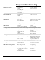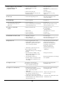
1
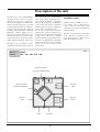
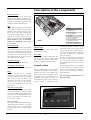
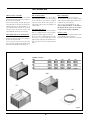
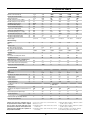
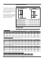
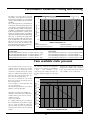
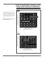
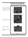
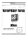
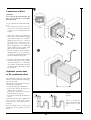
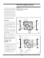
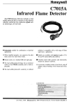
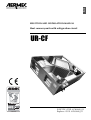
English SELECTION AND INSTALLATION MANUAL Heat recovery units with refrigeration circuit UR-CF RT A HHH H H H H HHH H IT EM L E T QU H H H IFI D C 3 E Y SY S IURCFPV. 0709. 6783480_03 Replace. 0512. 6783480_01 English Index Declaration of conformity 4 Remarks 5 Description of the units 6 Description of components 7 Accessories 8 Technical data 9 Operational limits 100 Sound data 100 Performance variations cooling and heating 11 Fans available static pressure 11 Fresh air temperature variations on the change of the expelled air temperature 12 Thermal efficiency, Pressure drop air side accessories MBC, SUF 13 Dimensions 14 Accessories Dimensions 17 Installation and use of the unit 20 Positioning of the supporting brackets 210 Connection of ducts 22 Hydraulic connections of the condensate drain 22 FCE free-cooling accessory 23 Electrical connections 24 Maintenance of the unit 25 Filters 25 Condensate drain pan 25 Heat recovery 26 Motor ventilating assembly 26 Heat exchanger coil 26 Waste disposal 26 Diagnosis and troubleshooting 27 Aermec S.p.A. 35044 Montagnana (PD) Italia – Via Luppia Alberi, 170 Tel. (+39) 0429 806311 Telefax (+39) 0429 806340 www . Aermecaer . com - Aermecaer @ Aermecaer . com DECLARATION OF CONFORMITY: We declare under our own responsability that the above equipment described as follows: 1. We declare under our own responsability that the above equipment described as follows: Harmonized standards: - EN 378: Refrigerating system and heat pumps - Safety and environmental requirements; - EN 12735: Copper and copper alloys - Seamless, round copper tubes for air conditioning and refrigeration. 4 2. designed, manufactured and commercialized in compliance with the following EEC Directive: - PED safety 97/23/CE - Machinery safety 98/37/CE - Low voltage equipment 73/23/CEE and successive modifications. - Electromagnetic compatibility (EMC) 89/3206/CEE and successive modifications. Montagnana, 04/075/2005 Managing director Paolo Gasparini Remarks This manual is an integral part of the documentation enclosed with the unit. It must be kept for future reference and must accompany the machine throughout its life. The manual defines the purpose for which the machine has been built and establishes its correct installation and the limits of its use. • This manual describes all the use, installation and maintenance instructions of the subject unit and the main accident prevention standards. Carefully and thoroughly read all the information referred to in this manual. Pay particular attention to the norms accompanied by the indication “DANGER” or “ATTENTION” since, if not observed, may cause damage to the unit or to people. If any malfunctions are found out, whciha are not included in this manual, please contact the local After-Sales Service immediately. • Aermec S.p.A. declines all liability for any damage caused by the improper use of the machine or the partial or superficial reading of the information contained in this manual. • Installation and maintenance must be performed by qualified and experienced personnel, having the requirements that are foreseen by law 46/90 and/or the DL 380/2001 for the electrical/electronic and air-conditioning installation, with consequent registration at the local CHAMBER OF COMMERCE, if this is not so, Aermec S.p.A. declines all responsibility regarding the safety of the product . THE MANUFACTURER DECLINES ALL LIABILITY FOR DAMAGE TO THINGS OR INJURY TO PERSONS AND ANIMALS CAUSED BY THE FAILURE TO OBSERVE THE INSTRUCTIONS AND STANDARDS IN THIS MANUAL. Although suitable risk analysis have been performed during the design of the URCF unit, PAY ATTENTION to the pictograms on the machine which help understand the manual better, rapidly catching the attention of the reader concerning the risks which can not be avoided or sufficiently limited through the use of technical protection means and measures. GENERAL HAZARD SIGNAL Carefully adhere to all the indications next to the icon. Failure to comply with the instructions may generate hazardous situations with possible damage to the health of the operator and user in general. DANGEROUS ELECTRICAL VOLTAGE SIGNAL Carefully adhere to all the indications next to the icon. The signal indicates components of the unit or, in this manual, specifies actions that could generate electrically-related risks. GENERAL PROHIBITION SIGNAL Carefully adhere to all the indications next to the icon that limit actions in order to guarantee better operator safety. MAIN WARRANTY CONDITIONS • The warranty does not cover payment for damages cause by the incorrect installation of the unit by the installer. • The warranty does not cover payment for damages cause by the improper use of the unit by the user. • The manufacturer is not responsible for accidents to the installer or user that are due to the improper use and incorrect installation of the unit. The warranty is not valid when: • the maintenance and repairs have been performed by unauthorised persons or companies; • the unit has been previously repaired or modified with spare parts that are not original; • the unit has not undergone suitable maintenance; • the instructions described in the present manual have not been followed correctly; • unauthorised modifications have been made. 5 N.B.: The Manufacturer reserves the right at all times to make any modification for the improvement of its product and is not obliged to add these modification to machines of previous manufacture, which have already been delivered or are being built. The warranty conditions are any subject to the general sales conditions at the moment the contract is finalised. Description of the unit The URCF series is the mono-bdamper solution to the needs of systems normally used in bars, restaurants, offices, meeting rooms. The URCF units, which are divided into five sizes with a rated airflow from 750 to 32000 m3/ h, have been designed to guarantee a healthy thermo-humidity condition allowing a suitable change of air in order to reduce the build-up of gas and unwanted particles present in the environment to be treated (cigarette smoke, unpleasant odours, sweat, dust, ...). The RFC unit, in addition to the ventilation, filtration and recovery of heat, also includes, in a mono-bdamper unit, a heat pump refrigerating circuit. This allows to obtain a complete machine which operates independently in all seasons and which is capable of combining the necessary renewal of air with an efficient recovery of heat. The accurate design of the machine combines the extremely compact size, which makes installation on suspended ceilings easier, with easy accessibility for the maintenance of all internal parts. This gives the opportunity, also thanks to the management and installation simplicity, to satisfy many system requirements. Available versions The RFC units are available in 5 sizes: Each model can be configured in such a manner to satisfy the system requirements by suitable combining the available options. The table in fig. 01 shows the procedure of the commercial acronym in the 5 fields from which it is made, which represent the options present. fig.01 Field 1, 2, 3 Field 4, 5 URCF : 075 - 100 - 150 - 210 - 320 : Exhaust air expulsion or inspection refrigerating circuit Exhaust air expulsion Internal air or inspection refrigerating circuit supply External air Internal air intake recovery External air By-pass for intake free-cooling 6 Description of the components Panels and structure: the structure is made up of 20 mm thick galvanised self-supporting sandwich panels with injected polyurethane insulation ( density of 40 kg/m3). The construction of the casing simplifies installation and maintenance. 4 4 3 5 6 6 1 Fans: double intake centrifugal fans with forwardcurved blades and with directly connected motor. The 230V - 50 Hz single-phase motor has one speed. The airflow is controlled by an electronic regulator at phase cut. The two regulators are set in the factory so as to supply the nominal performance; the air volume may be varied by +/- 150% to the nominal airflow, not to endanger the correct operation of the unit. Refrigerating circuit: this is a highly efficient and silent heat pump with scroll compressor, four-way valve for cycle inversion, evaporating coil, condensing coil, liquid receiver, liquid separator, double thermostatic valve, liquid indicator for the 1500 21000 3200 versions only and filter drier, high/low pressure switch. Condensate drain pan: made of peraluman, easily detachable. Evaporating/condensating coil: with Cu grooved tube and high efficiency Al fins. Filters: these are cell type with an corrugated septum positioned before the recovery unit on airflow supply and return. The standard filters are class G3 type in accordance with classification UNI EN 779 with weighted efficiency of 80%. They are 48 mm thick and are easily withdrawn for cleaning and replacement. 3 2 8 7 URCF Support brackets: allow the unit to be rapidly and securely fixed to the false ceiling. Accessibility: The unit may be inspected from below. The heat recovery unit, filters, condensate drain pan and fans can be easily removed from below by removing the lower two panels. Control system The unit is equipped with an electrical panel with power and regulation section (including the three-way valve for the additional hot water coil and related servomotor), aimed at guaranteeing the management of all refrigerating circuit functions. Also present: NTC temperature probe on the internal air recovery, external air temperature probe, Dirty filters pressure switch: a differential pressure switch is present, placed close to the electronic controllers, for the detection of the choking of the supply filter. It is possible to set the intervention value. Thre pressure switch includes clean contacts (NA, NC) to remote the alarm. Heat recovery unit: this is static with crossflow made of aluminium sheets. During winter operation, the average efficiency is above 50% ensuring first-class energy recovery from the air expelled from the room. 7 Legenda 1 Compressor 2 Electric panel 3 Centrifugal fan 4 G3 filter 5 Heat recuperator 6 Heat exchanger 7 Condensate drain 8 Electronic regulators air damper and related servomotor in the free-cooling version, pressure probe on the recovery filter. A remote control terminal is also supplied for the automatic management of the unit, remotable up to 1500 meter (cable not supplied). The unit is equipped for the management of a luminous sign (230V) which switches on in case of generic alarm or unit OFF, in conformity with the norms in force for rooms for smokers. The following operations can be performed on the microprocessor: switching on and off of the unit, summer/winter changeover, setting of set-point parameters, reading of room temperature. N.B. For further information refer to the User manual. Accessories MBC Hot water coil module This is an external module that can be installed downstream from the motor fan assembly on the fresh air flow, fitted with: Two-row water heating coil with copper pipes and aluminium fins with P2519 geometry. The manifold collectors are equipped with a ½" G UNI 3208 threaded connector for the water inlet and outlet. The three-way valves and related ON/OFF actuator are also included. MBX Module with electric heating battery This is an outside module that can be installed downstream from the motor fan assembly on the fresh air flow, fitted with: Electric heating element with armoured finned elements equipped with double safety thermostat with automatic and manual reset. G4F G4 efficiency filters The units can be fitted with two cell-type filters with corrugated septum in class G4 according to the UNI EN 779 classification (weighted efficiency of 90%) which can be placed as a replacement of the G3 filters. The filtrating cell is 48 mm thick. SUF Module with silencers The accessory is made up of two modules that are equipped with silencer baffles positioned on the supply and exhaust. They are made of rockwool panels with the surfaces in contact with the air and protected by a polyester film held between two galvanised and micro-perforated laths. FGC circular flanges The accessory is supplied as a single unit. The accessory is made up of flanges which connect to the rectangular port of the unit so as to allow the use of circular ducts. The accessory is not available for size 320. N.B. for further information, see the tables in this manual and the various accessories kits; see fig. 02 below regarding compatibility FCE Free-cooling The “free-cooling kit ” includes 2 dampers with related ON/OFF 230V servomotors. For further information refer to the Use manual. Available accessories MBX Mod. MBC MBX G4F SUF FGC FCE 075 MBC075 MBX075 G4F075 SUF075 FGC075 FCE075 100 MBC100 MBX100 G4F100 SUF100 FGC100 FCE100 150 MBC150 MBX150 G4F150 SUF150 FGC150 FCE150 210 MBC210 MBX210 G4F210 SUF210 FGC210 FCE210 320 MBC320 MBX320 G4F320 SUF320 FCE320 MBC SUF FGC fig.02 8 Technical data MODEL URCF External air nominal flow rate Recovery air nominal flow rate Minimum airflow rate Available static pressure (in supply) (1) Available static pressure (in exhaust) (1) Sound pressure level at 1 m (6) Recovered heating capacity (3) Recovered refrigerating capacity (2) Compressor heating capacity (3) Compressor refrigerating capacity (2) Total heating capacity (rec. + compr.) (3) Total refrigerating capacity (rec. + compr.) (2) Total power input during heating (3) Total power input during cooling (2) Electric supply Heat recovery Efficiency (3) Fans Number of fans Fans total nominal input power Fans maximum total input power Fan speed Protection class Filters Classification according to the EN779 Quantitative efficiency Refrigerating circuit (compressor) Winter mode compressor input power (3) Summer mode compressor input power(2) Compressor maximum power input ACCESSORIES MBC Water heating coil Rows Front surfaces Air side pressure drop at nominal flow rate Pa Heating capacity (4) Heating capacity (5) Air outlet temperature (4) Air outlet temperature (5) MBX - ELECTRIC HEATING COIL Alimentation Heating capacity Air side pressure drop to the nominal airflow Pa Stages Electric heating element power input Air outlet temperature (7) MANIFOLD DIAMETERS Condensate drain pan discharge diameter Water coil manifold diameter Caution: the electronic regulators that are incorporated in the machine allow to regulate the air flow in the limits indicated in the previous table in order to set the system. Once setting has been completed, the regulators no longer need to be touched. m3/h m3/h m3/h Pa Pa dB(A) kW kW kW kW kW kW kW kW ph-V-Hz 075 750 750 640 256 244 53 3,2 0,9 5,3 4,6 8,5 5,5 1,8 3 1- 230-50 100 10000 10000 850 2101 203 55 4,7 1,3 6,7 6,4 11,4 7,7 2,3 3,6 1-230-50 150 15000 15000 1275 223 206 57 6,6 2 9,5 8,3 16,1 100,3 3,7 5 3+N-400-50 210 210000 210000 1785 146 134 59 9,8 2,9 14,1 14 23,9 16,9 4,5 6,7 3+N-400-50 320 32000 32000 2800 267 246 62 14,9 4,4 16,6 150,3 31,5 19,7 5 8 3+N-400-50 % 51 56,4 52,8 55,6 53,9 n° kW A settable IP 2 0,75 5 settable 55 2 0,75 5 settable 55 2 1,2 8,6 settable 55 2 1,2 8,6 settable 55 2 2,1 13,2 settable 55 % G3 80 G3 80 G3 80 G3 80 G3 80 kW kW A 1,2 2,4 100,9 1,7 3 14 2,6 4 6,7 3,4 5,6 9,7 3,8 5,8 11,1 n° m2 11 kW kW °C °C 075 2 0,13 19 4,5 1,4 46 34 075 150 2 0,24 25 8,4 2,7 45 320 150 210 2 0,24 41 11 3,5 44 320 210 320 2 0,29 kW 100 n° A °C 3 100 1 4,6 47 100 2 0,13 17 5,5 1,7 45 320 100 3~ 400V 50 Hz 4,5 100 1 6 45 6 100 1 9,1 45 9 100 1 12 45 12 1 19,7 41 1” 1” 3/4” 1” 3/4” 1” 3/4” 1” 3/4” 3/4” (1) Fan power supply: 230 V; nominal airflow rate; without accessories; (2) Operating conditions: return air 26°C 50%, external air 34°C 50%; (3) Operating conditions: return air 20°C 50%, external air -5°C 80%; 9 150,6 5 42 32 320 (4) inlet/outlet water temperature 70/60°C in condition (3) with compressor running; (5) inlet/outlet water temperature 45/40°C in condition (3) with compressor running; (6) At a free field distance of 1 m with ports canalized; (7) In condition (3) with compressor running. Operation limits In their standard set-up, the equipment is not suitable for installation in a saline environment. The maximum and minimum limits of the airflow rate to the exchanger are indicated by the curve of the pressure drops diagram. Refer to fig. 043 for the operating limits. Winter mode: (heat pump) Summer mode: 46 ext (°C) 25 t ext (°C) 10 N.B: Please contact Aermec technical sales office in the event it is necessary to operate the machine outside the limits indicated in the diagram. 0 0 t int (°C) -10 0 0 18 16 30 t int (°C) Max external temperature during cooling Min external temperature during cooling Max internal temperature during cooling Min internal temperature during cooling Min external temp with heat pump operating Max external temp with heat pump operating Max internal temp with heat pump operating Min internal temp with heat pump operating °C °C °C °C °C °C °C °C 075 46 100 30 18 -100 25 30 16 100 46 100 30 18 -100 25 30 16 30 150 46 100 30 18 -100 25 30 16 fig.03 210 46 100 30 18 -100 25 30 16 320 46 100 30 18 -100 25 30 16 Sound data • Data outside the panel: (the data are calculated at the following conditions: 1 m. distance from the unit, ducted supply vent and in free field) 075 100 150 210 320 63 dB 56 59 62 64 67 125 dB 55 60 65 69 74 Sound pressure by band central frequence (Hz) 250 500 10000 2000 4000 dB dB dB dB dB 51 50 49 44 40 54 52 50 45 41 57 54 51 47 42 60 55 52 48 43 63 57 53 49 44 8000 dB 320 35 36 38 39 Sound pre. Sound Pre. Sound Pow. Total Total Total dB dB (A) dB (A) 60 53 64 64 55 66 68 57 68 71 59 70 75 62 73 • Sound data on the supply fan vent Sound pressure measured at 3m distance from the free vent of the supply fan: 075 100 150 210 320 63 dB 65 66 67 66 69 125 dB 57 58 59 61 61 250 dB 54 56 58 58 59 500 dB 57 60 62 67 64 10000 dB 54 57 60 62 71 2000 dB 50 57 61 65 71 4000 dB 53 57 63 68 63 8000 dB 48 52 57 63 58 Sound pressure dB dB (A) 67,0 60 68,8 64 71,1 68 73,8 72,5 76,1 75,5 250 dB 59 63 63 60 68 500 dB 61 66 65 66 71 10000 dB 62 66 66 66 71 2000 dB 58 63 64 65 71 4000 dB 51 57 59 61 68 8000 dB 44 50 52 54 62 Sound power dB dB (A) 68,7 65,3 73,3 70 72,9 70,3 72,3 70,8 78,2 76,6 2000 dB 9 4000 dB 14 8000 dB 11 Sound power level from the supply vent: 075 100 150 210 320 63 dB 57 59 57 53 61 125 dB 64 69 68 65 71 • Attenuation of sounda data with SUF - Module with silencers (accessory) SUF 63 dB 9 125 dB 0 250 dB 2 500 dB 5 10000 dB 5 10 Performance variations cooling and heating Heating capacity Refrigerating capacity Multiplicational coefficient The URCF series heat recovery unit with refrigerating circuit allow the renewal of the internal air giving the necessary hourly change in order to obtain the ideal comfort conditions. The use of a high efficiency cross-flow heat recovery unit and a heat pump refrigerating circuit allows, in most applications and in the most common external air temperature conditions, in addition to the neutralisation of the heating load of the external air, to supply an adequate heating and cooling capacity to compensate the internal heating loads. Fig. 4 illustrates the graph from which it is possible to take the coefficients to be multiplied by the nominal values which are present in the technical data table so as to be able to determine the total refrigerating and heating performance based on the outside conditions. Outdoor air temperature [°C] Key Internal air temperature Summer operation: 26 °C 50% RH Internal air temperature Winter functioning: 20 °C 50% RH fig.04 Corrective coefficient for the cooling capacity according to the variation of the room temperature in summer and winter mode: SUMMER MODE: WINTER MODE: Room air temperature 22°C, 50% RH --> corrective coefficient = 1,050 Room air temperature 18°C, 50% RH --> corrective coefficient = 0,980 Room air temperature 24°C, 50% RH --> corrective coefficient = 1,025 Room air temperature 20°C, 50% RH --> corrective coefficient = 1 Room air temperature 26°C, 50% RH --> corrective coefficient = 1 Room air temperature 22°C, 50% RH --> corrective coefficient = 1,020 Room air temperature 28°C, 50% RH --> corrective coefficient = 0,975 Room air temperature 24°C, 50% RH --> corrective coefficient = 1,040 Fans available static pressure nominal delivery flow rate 15000 m3/h; nominal recovery flow rate 15000 m3/h; available delivery static head = 223 Pa; available recovery static head = 206 Pa. It is supposed that the pressure drops of the air distribution system on the supply side are equal to 21000 Pa, while the pressure drops of the air distribution system on the exhaust side are equal to 180 Pa. The "Effective useful pressure/Nominal useful pressure" reports are 21000/223 = 0.94 and 180/206 = 0.87 respectively. The coefficients that can be taken from the graph are 1.08 and 1.18. Therefore the effective flow rate on the supply side is 15000 x 1.08 = 1620 mc/ h; the effective flow rate on the exhaust side is 15000 x 1.18 = 1770 mc/h. Effective useful head/Nominal useful head The variations of the static pressure used by the fans to change the air flow (which can be set by means of the electronic regulators during the setting phase) in relation to the nominal values present in the technical data table, are represented in the graph of fig. 5. The curve is valid for all sizes of the RFC series. Keep the feed to the fans at the maximum value. As an example, a unit of the RFC 150 series is considered. The following performances are taken from the technical data table: Effective flow rate/nominal flow rate 11 fig.05 Fresh air temperature variations on the F change of the external air temperature Summer use Variation of the inlet air temperature (°C) N.B. The following diagrams are typical for all sizes, but without accessories At the nominal air flow To the nominal air flow + 150 % At the nominal air flow - 150 % External air temperature (°C) Conditions: exhaust air 26°, 50% R.H. Winter use Variation of the inlet air temperature (°C) The following charts allow to determine the variation of the temperature within the room on the variation of the external conditions. The variability of the air flow is that allowed to guarantee that the refrigerating circuit operates correctly. At the nominal flow rate - 150% At the nominal flow rate At the nominal flow rate + 150 % External air temperature (°C) Conditions: exhaust air 20°, 50% R.H. 12 Thermal efficiency, Pressure drop air side for accessories MBC, SUF Corrective factor The diagram in fig. 06 allows to determine the coil thermal efficiency of the MBC accessory for each model based on the Td of the inlet water and Td of the inlet water air. The corrective factor to multiply for the nominal capacity value are present in the technical data table. 70/60 °C 45/40 °C External air temperature [°C] Pa fig.06 .#$ Fig. 075 illustrates the pressure drops (Pa) on the air side based on the flow rate for the MBC and SUF accessories Pressure drop air side 46' .#$ 46' .#$ 46' fig.075 Air flow rate m3/h kPa -"# Fig. 08 illustrates the pressure drops (kPa) water side of the MBC accessory coil. N.B.: The pressure drops illustrated in the diagram also include those of the threeway valve. Pressure drop water side -"# -"# fig.08 Water flow rate l/h 13 Dimensions URCF 075-100 Supply fan By-pass for free-cooling External air suction External air suction Electric panel Expulsion of exhaust air or inspection of refrigerating circuit Weights and centres of mass kg URCF 075 21050 URCF 100 220 Gx Gy 700 700 650 650 14 h'5.) Exhaust fan Expulsion of exhaust air or inspection of refrigerating circuit URCF 150-210 Supply fan By-pass for free-cooling External air suction Expulsion of exhaust air or inspection of refrigerating circuit Gx Gy 800 760 750 750 15 Electric panel h'5.) Weights and centres of mass kg URCF 150 305 URCF 210 320 External air suction Exhaust fan Expulsion of exhaust air or inspection of refrigerating circuit URCF 320 External air suction Expulsion of exhaust air or inspection of refrigerating circuit Pesi e baricentri kg Gx Gy URCF 320 400 850 800 16 Electrical panel h'5.) By-pass for free-cooling External air suction Supply fan Exhaust fan Expulsion of exhaust air or inspection of refrigerating circuit Accessories Dimensions SUF - Silencer baffle modules Key I Inspection panel set 2. Lower panel bdampering profile 3. Upper fixing bracket 4. Silencer 5. Baffles fixing bracket 6. Duct accessories connection flange H I M C G M 1. B D % ! & % Mod. [mm] URCF 075-100 A 600 B 835 C 400 D 30 E 31,5 F 537 G 3207 H 490 I 50 L 632 M 1008 , 17 URCF 150-210 600 835 500 30 31,5 537 437 490 50 632 1008 URCF 320 600 835 550 30 31,5 537 487 490 50 632 1008 MBC - Water coil modules MBX - Electrical coil modules MBC MBX Mod. [mm] URCF 075-100 A 600 B 435 C 400 D 30 E 31,5 F 537 G 3207 H 250 I 50 L 632 M 28 N 40 O 85 P 278 Q 127 18 URCF 150-210 600 435 500 30 31,5 537 437 250 50 632 28 40 85 278 127 URCF 320 600 435 550 30 31,5 537 487 250 50 632 28 40 85 278 127 # &ORIMM # Dampers and actuators (included in the free-cooling kit) ( " O Mod. [mm] URCF 075-100 B 450 H 3100 URCF 150-210 550 4100 Circular flanges (FGC accessory) 380 mm 19 URCF 320 600 460 Unit accessibility 20 Installation and use of the unit General safety requirements WARNING! The URCF series units are destined for civil and tertiary use: for all other applications (in highly corrosive environments, in potentially explosive atmospheres etc. ) its use is not permitted. • Make sure that the unit has not been damaged during transportation before installation: The use of the damaged machine might be dangerous; • I n s t a l l a t i o n a n d e x t ra o r d i n a r y maintenance must be performed by qualified people in accordance with the present standards; • The unit must not be used to recover equipment, spare parts. Any use other than those indicated in this manual may generate hazards and is therefore prohibited; • Before performing maintenance or cleaning operations, make sure that the unit is disconnected and ensure that it is not reconnected without informing the person who is presently working on the unit; • During maintenance and cleaning, pay attention to possible burning of the heating coils; • Before starting the unit make sure that the electrical parts have been connected to the earth system of the building; • Before starting the unit make sure that the fan vents have been ducted or include safety meshes; • The unit is not designed for external installation: external installations require particular technical characteristics and devices which these units cannot guarantee; • During installation, maintenance and cleaning, wear suitable Individual Protection Devices (IPD). 14.1.1 General safety requirements The units are fitted with: • an adhesive label (fig. 075a) which indicates the model, the gross weight and the customer • an adhesive label (fig. 075b) which indicates the main technical data such as the model, nominal air volume, efficiency of the heat recovery unit, electrical data and performance of the coils. • Each URCF unit is identified by means of a serial number on the plate N.B.: The serial number must be indicated for future reference when contacting Aermec S.p.A. Transport and handling CAUTION! During the handling phase, wear proper individual protection devices (IPD) Before installation and use you are recommended to fully unpack the base unit and the all the components that come with it. The units are supplied packed with polythene film and, as a standard, on wooden pallets. For transport reasons, some accessories travel separately from the standard unit and are to be reassembled by the installer following the instructions in this manual Transport Refer to the weight indications on the plate on each unit in order to transport the unit safely. In any case, the following precautions must be taken when transporting the unit: • The unit and its accessories, if any, must not be subject to intense knocks which could compromise the integrity of the structure and internal parts; • The unit and possible accessories must be suitably secured to the platform of the transportation by means of cables or similar in order to prevent its movement; • the unit and accessories must be protected in order to prevent protruding parts such as the coil connections, condensate drain, electrical components, etc., from being knocked during transport; • the items must be protected against bad weather during transport. Checks at material receipt 21 When the unit is received it is necessary to carry out an initial inspection to make sure that: • all parts are present ; • the unit and accessories are not damaged. If there are signs of damage it is necessary to specify it on the carriage note. The controls are the following: • integrity of the finned coil manifolds and condensate trays; • water connections (that these are protected with the rubber plugs). If they are not provide suitable closure devices; • integrity of the panels; • integrity of the electrical panel and electrical/electronic parts Installation You are recommended to carefully follow the indications in the sections below when installing the equipment. The sections are in chronological order in order to make each phase of the installation easier. The necessary technical space must be verified before installation fig.08: • for the arrangement of the supply and exhaust ducts as well as those for the free-cooling; • for the dampers with free-cooling function; • for the passage of the power supply fig.075 a fig.075 b • for the components (three-way valves, condensate drainage traps, etc.) without which the correct functioning of the unit can not be guaranteed; • for the correct cleaning and maintenance operations. In particular: • a space of at least 200 mm must be available for the trap in correspondence with the condensate drain (fig. 11). Key A = 800 mm B = 200 mm C = 200 mm D = 200 mm ! " $ # fig.08 Positioning of the supporting brackets The unit must be positioned on a flat surface to avoid: • the drainage of the motor fan a s s e m b l i e s c a u s e d by w e i g h t imbalance • the incorrect functioning of the condensate drain. Fischer screws not supplied The unit and the coil and silencer module are equipped with "L" supporting brackets for horizontal installation. N.B.: You are recommended to place rubber dampers between the brackets and the walls to decrease the vibrations generated by the unit. Check the dimensional layout in this manual for the correct positioning of the brackets: • drill the wall in correspondence with the points indicated in fig.09 (point 1); • disassemble the brackets from the unit or from the coil or silencer module by unscrewing the screws in correspondence with the holes (point 2); • screw the brackets to the wall (screws not supplied) in correspondence with the holes (point 3); • in correspondence with the holes (point 4), partially tighten one screw for each bracket to the unit or to the coil or silencer module; Glue not supplied Rubber shock-absorbers not supplied Fischer screws not supplied Installation material not supplied as part of the kit fig.09 22 Connection of ducts CAUTION! never start up the unit when the fan ports are not ducted or covered by protective mesh. Olona cloth vibration-damping joint See fig. 100 for the installation of the ducts: • use adequate brackets to sustain the ducts in order to avoid that the recovery unit is overloaded by their weight; • connect the supply and exhaust ports to the ducts using vibration-damping joints (olona cloth). The vibrationdamping joint must be screwed to the panel with self-tapping screws, positioning the screws inside the border highlighted in the following layout avoiding that the olona cloth joints are over stretched (point 1); • connect a earth wire to the vibrationdamping joint to act as a jumper to guarantee the unipotentiality between the ducts and the recovery unit; Electrical earth wire not supplied • place the supply duct with a straight section of at least one meter, before the bends, branches, etc., and make sure that the ductling does not have inclinations of the divergent sections greater than 7°. Supply duct Hydraulic connections of the condensate drain The condensate drain pan is provided with a 1” diameter threaded discharge pipe G UNI 3208. The drainage system should feature an adequately sized trap to: • freely discharge the condensate; • prevent the undesired entry of air into the vacuum systems; • prevent the undesired exit of air from the pressure systems; • prevent the infiltration of odours or insects. In the lower part of the syphon must have a bleed cap or must anyway permit Aermec dismantling for its cleaning. Rules to follow for the scaling and production of the syphon are given below. Minimum length 1 m max divergence 7° P neg. H1 = 2P H2= H1 / 2 P pos. H3 H3 H1 H1 H2 H2 where P is the pressure expressed in mm of the water column (1 mm c.a. = 9.81 Pa). fig.11 23 FCE free-cooling accessory The assembly of the "free-cooling kit" accessory must be performed by qualified personnel in accordance with the present standards and must be made following the indications in the electrical layout supplied with the unit. The compressor is off during the functioning of the unit in the freecooling mode. The temperature settings are pre-set at fixed values (on request these values can be changed by contacting the After-Sales office). See the indications in fig. 12 for the installation of the free-cooling kit. CAUTION! Before assembling the free-cooling kit, make sure that the power is not connected to the unit. Damper A Operation The free-cooling function foresees that the air expelled from the room does not affect the heat recovery unit, passing directly to the outside through a duct connected to the damper B. Thus, the fresh air flow passes through the filter and the heat recovery unit without being touched by the heat recuperator. In order to use the free-cooling function a duct is required to connect to damper A and another to connect to damper B. The two dampers A and B have an opposing function. When the outside temperature is close to the ideal temperature of the room, damper A is closed while damper B is open. Damper A can be positioned on the side as indicated in the line diagram. The compressor is off when the unit is operating in free-cooling. EXTERNAL INTERNAL Damper B fig.12 MES Exhaust damper actuator Assembly of the accessory For the assembly of the free-cooling accessory please refer to fig. 13 and 14 • p l a c e t h e t wo d a m p e r s w i t h servomotors MES and MESF as in the previous diagram; • make sure that the damper with the MES servomotor is closed during the free-cooling function while the damper with the MEFS servomotor is open (opposing functions); • connect the damper servomotors; EXTERNAL INTERNAL BTR Room temperature probe already present BTE Outside air temperature probe already present 24 MESF Free-cooling Damper actuator fig.13 Electrical connections The unit is completely wired in the factory and requires the power supply, intercepted with inline protections, indicated on the unit specification plate in order to be started. The installer should define the power supply line based on the length, the type of cable, the absorption of the unit and the displacement. TAB.3 All electrical connections must be in accordance with the present standard at the moment of installation. currently in force. Every electrical user must be connected to the system's earthing system. Use the connectors with the earth symbol to connect the earthing of the unit and possible accessories to the earthing of the building. Respect the installation power supply and environment conditions Keep the panel and wiring away from electric and magnetic fields that could disturb, such as inverters, high voltage CAUTION: Refer to the electrical layout supplied with the equipment for installation needs. Check that all power cables are correctly secured to the terminals when switched on for the first time and after 30 days of use. Afterwards, check the connection of the power cables every six months. Slack terminals could cause the cables and components to overheat. The electrical wiring and connections must be done persons qualified to do so in accordance with regulations TAB.3 Operating voltage ± 100% of the rated voltage (EN60204) Frequency ± 1% of the continuous frequency ± 2% for short periods Operating room umidity Altitude up to 10000 m a.s.l. (EN60204) Operating room temperature commissioning checks. Before start-up check that: – the system has been charged and the air has been blown out; – the electrical connections have been made correctly; – the line voltage is within the permitted allowance (±100% of the rated value); Before the first start-up of the heat recovery unit check the following points: • the exact positioning of the panels in correspondence with the motor ventilating assembly that require opening by means of a screw-driver; • the fixing of the unit to the wall; • the earthing of the unit to the buildings earth system; • the connection to the ducts; • the condensate drain connection to the trap; • the insulation of the tubes to the coils ; • the ground wires of the electrical components; • the absence of air in the water coils. In particular check that: • the electrical connection has been performed correctly and that all terminals have been sufficiently tightened; • the voltage on the terminals is 230 V ± For detailed information regarding the operating parameter settings and all other machine or control card operations, consults the user manual. CAUTION! Make sure that all the instructions have been complied with before carrying out the from 30% to 95%, without condensate or the formation of ice (EN60204) Before start-up Unit start-up power supply lines,etc. CAUTION! Once the connections have been made, check that: all the cables have been correctly connected, and that there are no short circuits between terminals and the terminals and ground. the electrical terminals both within the electrical panel as well as in the terminal board of the compressor are secured and that the mobile and fixed contacts of the remote control switches do not show signs of wear. Do not block the air intake of the panel. 25 from +5°C to 40°C 5% (for units with single-phase power) or 400 V ± 5% (for units with three-phase power): If the voltage is subject to frequent change, contact our Technical department in order to select the necessary protection; • there are no leaks of refrigerant through the use of a leak detector. CAUTION! Before start-up, check that all the panels of the unit are in place and secured with the screws. Checks during operation Requirements of gas R4075C Check the rotation of the compressors which are energised by a 3 phase system: if the suction pressure does not decrease and the supply pressure does not increase to the normal values, switch off the power and invert two phases of the three-core input cable and turn the power back on to check that this was not incorrectly connected: never modify the internal wiring connections otherwise the warranty will no longer be valid. The air flow rate values must not be lower than 150% of the nominal values indicated in the technical specifications table. The circuit chillers that work on R4075C cooling gas require particular attention during assembly and maintenance, to prevent operating faults. Therefore it is necessary to: - Avoid refilling with oil different from the one specified and already used in the compressor. - If there are gas leaks causing the unit to be even partially empty, do not refill with refrigerant, but empty the unit completely and refill it with the foreseen amount. - In the event of replacement of one of the refrigerating circuit parts, do not leave the circuit open for more than 150 minutes. - In particular, in the event of replacing the compressor, complete the installation within the abovementioned time after the rubber plugs have been removed. - When empty, do not switch on the compressor; do not compress the air within the compressor. - When using R4075C gas bottles, it is recommended to take care of the maximum number of drawings permitted in order to guarantee the correct ratio of components of the R4075C gas. If an electrical resistance is present, check the cut-in by measuring its electrical absorption. Maintenance of the unit CAUTION! During the maintenance phase, wear proper individual protection devices (IPD) • Before performing maintenance and/ or cleaning operations on the unit, make sure the unit is disconnected from the power supply and that it can not be turned back on without the knowledge of the person performing maintenance, and that the heat exchanger coils are not working. • During maintenance the weight of the inspection panelling could hinder the work The RFC series recovery units have been designed to require very little maintenance and to make every operation easy. Some simple pieces of advice follow for the proper maintenance of the unit. • remove the inspection panel with knobs; • remove the filters; • clean the filters; • replace all parts in reverse order. Condensate drain pan Filters Fi l t e r c l e a n i n g i s i m p e ra t ive t o maintain high air quality in the room. The synthetic filters installed in the URCF unit can be regenerated with compressed air or can be washed with cold water. To disassemble the filters: 26 Dirt can hoard up in the condensate d r a i n p a n . Yo u a r e t h e r e f o r e recommended to clean the pan regularly and check that the discharge pipe is not clogged. To remove the condensate drain pan of the heat recovery unit: • remove all bottom panels; • disassemble the cross bar; • disconnect the pan from the condensate drain pipes; • disassemble the pan supporting brackets; • clean the pan; • replace all parts in reverse order. In order to access the condensate drain pan on the coil module, detach the module from the unit and disassemble it. Heat recovery The heat recovery unit can be cleaned with a jet of compressed air or cold water. To disassemble the heat recovery unit: • remove the condensate drain pan; • remove the heat recovery unit supporting brackets; • clean the heat recovery unit; • replace all parts in reverse order. Motor ventilating assembly The motor ventilating assembly needs to be checked to see how clean the rotor is, whether there is corrosion o r d a m a g e , a n d wh e t h e r t h e r e are abnormal noises. If necessary disassemble the motor fan assembly as follows: • remove all inspection panels; • disconnect the power supply cable; • unscrew the four screws that hold each of the motor fan assemblies to the frame; • check the motor fan assemblies and replace them if necessary; • replace all parts in reverse order. Heat exchanger coil To maintain an efficient heat exchange the coils must be cleaned with a jet of compressed air and the circuit (water coil) must be free from air. To access the heat exchanger coil of the MBC accessory, disconnect the module from the unit and disassemble it . PERIODIC COMPONENT OPERATIONS Filters Check their cleanliness twice a week Heat exchanger coil Check integrity of pack each year Condensate pan Check cleanliness each year Heat recovery unit Check integrity of the deck each year The table indicates the maintenance operations concerning each component, indicating the type of check to perform and when it should be performed. The frequency is approximate and varies depending on the working and environmental conditions in which the heat recovery unit operates. Waste disposal At the end of their operating life, the URCF units must be disposed of according to the present laws. The main components including the unit of the URFC series are made from: • Galvanised sheet steel (panels , condensate drain pan, fans); • aluminium sheet metal (coil fins, dampers, electrical motor casing); • the cooling gas is recuperated by specialised personnel and forwarded to the disposal centre; • copper (coil tubes, electric motor winding ); • polyurethane foam (insulation of the sandwich panels); • rock wool (silencers); 27 • the compressor lubrication oil is also recuperated and forwarded for disposal. Diagnosis and trouble-shooting 1. Insufficient air flow rate • Fans rotation speed too low • Pressure drop of the distribution system underestimated • Blocked filters • Blocked intake grating • Coil incrustation • Clean the components increase the fan speed 2. Excessive air flow rate • Fans rotation speed too high • Pressure drop of the distribution system overestimated • Filters not fitted • reduce the fan speed 3. No air flow rate • Power supply off • Electric motor burnt out • Make sure power supply is available • Replace the electric motor 4. Abnormal noise • Excessive flow rate • Bearings worn or defective • Foreign objects on the fan blades • Reduce flow rate • Replace bearings • Clean blades 5. Water movement • Trap Blocked • No trap or incorrectly carried out • Clean trap • Use an adequate trap 6. The compressor does not start • Defective connection or contacts open • Thermostat does not respond • Check the voltage and close the contact • System at temperature, no request; check the setting and the functioning • See point 9) and 100) • Safety device does not respond • Defective compressor 7. The compressor does not start • Compressor burnt out or seized • Compressor remote control switch de-energised • Power circuit open • Fit filters • Replace compressor • Replace compressor • Check the voltage across the operating time of the protection; automatic compressor shutdown • Check why the protection cut in compressor; automatic shutdown 8. The compressor starts and then stops • Defective compressor remote control switch • Check and if necessary replace it • Defective compressor • Check and if necessary replace it 9. The compressor does not start due to the intervention of the high pressure switch •Pressure switch out or order • Excessive refrigerant • Check and replace • Discharge excess gas • Presence of incondensable gas in the refrigerating circuit • The condensate coil is not sufficiently covered in air • Blocked refrigerant filter • Refill the circuit after having discharged and placed in vacuum. • See point 1) 28 • Check and replace 100. The compressor does not start due to the intervention of the low pressure switch • Pressure switch out of order • Machine completely empty • Poor air flow • Blocked refrigerant filter •The thermal expansion valve does not function correctly • Check and replace • See point 11) • Check the air duct and the state of the filters. • Check and replace • Check, clean or if necessary replace it. 11. Lack of gas • Leak in the refrigerating circuit • Check the refrigerating circuit with a leak detector 12. Hot liquid pipe • Lack of refrigerant • See point 11) 13. The refrigerating circuit functions correctly but with insufficient proficiency • Lack of refrigerant • Presence of humidity or incondensable in the refrigerating circuit • See point 11) • Replace the filter and if necessary drain and refill the circuit 14. Compressor suction tube frosted • Thermal expansion valve • Poor air flow • Lack of refrigerant • Blocked liquid filter • Check the valve and if it is not working correctly replace it • Check filters, fans and ducts. • See point 11) • Clean or replace 150. Abnormal noise in the system • Vibrations in the pipes • Noisy compressor • Noisy thermostatic valve • Secure the pipes • Check electrical phases connection • Check and add refrigerant 16. Evaporator coil • Lack of refrigerant in the circuit: before bubbles visible in the indicator. • Thermostatic expansion valve over . closed: suction pipe too hot • Check for leaks and eliminate them topping up with refrigerant . • Reduce the overheating of the thermostatic expansion valve turn the valve stem and check the suction pressure . • Change the valve or free the control pipe. • Thermostatic expansion valve over . closed: expansion valve bulb partially blocked or pressure intake pipe blocked • Filter-drier blocked: bubbles in the flow indicator and liquid pipe colder at the filter drier outlet • The manifold feed pipes are blocked or oil has accumulated in the coil: not all of the evaporator circuits are working • Change the filter-drier. • Remove the obstruction; clean or change the evaporator. 17. Compressor too hot •Thermostatic expansion valve over closed: excessive overheating of the evaporator discharge gas 18. Compressor to cold and noisy • Expansion valve over open: • Measure and reset the overheating the system works with the overheating by closing the valve to low (return of liquid to the compressor). • Thermostatic valve out of order: the stem or • Replace the valve or free the the seat of the expansion valve is pressure inlet pipe corroded. Pressure inlet pipe blocked. • Foreign objects between the stem and the seat • Clean the stem and the holes of the of the thermostatic valve: abnormal function thermostatic valve of the thermostatic valve 29 • Reduce the overheating of the thermostatic valve NOTE NOTE AERMEC S.p.A. 37040 Bevilacqua (VR) - Italien Via Roma, 44 - Tel. (+39) 0442 633111 Telefax (+39) 0442 93730 - (+39) 0442 93566 www . aermec . com carta riciclata recycled paper papier recyclé recycled Papier Technical data shown in this booklet are not binding. Aermec S.p.A. shall have the right to introduce at any time whatever modifications deemed necessary to the improvement of the product.