1
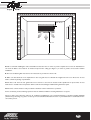
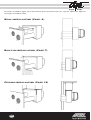
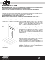
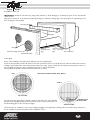
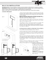
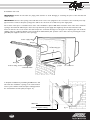
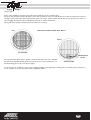
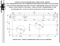
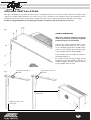
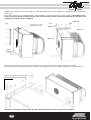
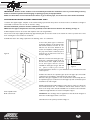
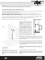
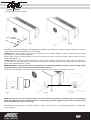
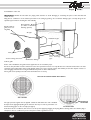
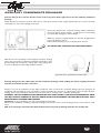
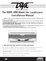
The RDW 9RN Model Air conditioner
Installation Manual
· CAREFULLY FOLLOW THE INSTRUCTIONS BELOW TO ENSURE THE IDEAL OPERATION OF
THE AIR CONDITIONER.
· HANDLE THE UNIT WITH CARE AND NEVER TURN THE AIR CONDITIONER UPSIDEDOWN DURING INSTALLATION.
· NEVER REMOVE THE UNIT'S REAR PANEL FOR ANY REASON IN ORDER TO
AVOID COMPROMISING OPERATION.
· AT THE END OF INSTALLATION, EXPLAIN THE UNIT'S OPERATION TO THE CLIENT USING
THE OPERATION AND MAINTENANCE MANUAL.
· GIVE THE OPERATION AND MAINTENANCE MANUAL TO THE CUSTOMER.
1. SELECTING THE INSTALLATION POSITION
The position of the air conditioner is extremely important for both correct operation and the comfort of the room or area.
Choose the unit's position together with the customer while taking into consideration the following points:
A. The air must be distributed as evenly as possible throughout the room, taking into consideration that warm air tends to rise
and cool air tends to fall.
B. The flow of air emitted by the unit must never strike the room's occupants directly.
C. Internal units must never be obstructed by furniture or curtains, etc.;
21
min 15 cm
200 cm
fig. 1
D. We recommend installing the unit at least 200 cm above the floor in order to permit complete and correct air distribution in
the room. A distance of at least 15 cm must be kept from the ceiling (see Figure 1) in order to permit correct wall or built-in
installation.
E.The rear ventilation grills must be free from obstacles to permit a free flow of air.
F. Make sure that the flow of air expulsed from the rear grills does not disturb the neighbours and is not directed to an area
with a continuous passing of pedestrians.
G. The flow of air from the rear grills must not be sent into a closed room because if this expulsed air is injected into an area
without free circulation the temperature will rise and the unit will begin malfunctioning with lower yield.
H.The unit's controls must be easily accessible to facilitate routine maintenance operations.
I. The condensate produced during operation must be eliminated without creating disturbance to anyone.
These are just a few of the basic rules for air conditioner installation. In case of unusual situations or doubts regarding feasibility
(dimensions, positioning, etc.) please contact your nearest Technical Assistance Center or your Manufacturer's technical/commercial contact person.
22
We provide an installation diagram below that summarises all the information found in the respective chapters that explain the
various types of installation possible:
Wall installation (Page. 4)
Built-in installation (Page 7)
Ceiling installation (Page 12)
23
WALL INSTALLATION
IMPORTANT: Cordon off the outdoor area immediately beneath the installation area to prevent falling masonry
debris or chunks of plaster from damaging or injuring property and people below.
Make sure that there are no electric hoses or gas or water pipes inside the parts of the wall to be drilled.
ASSEMBLY PROCEDURE
1. Position the supplied paper template on the wall and using a pencil mark the positions of the two holes to be drilled and the position of the support bracket at a height of around 200 cm from the floor and 15 cm from the ceiling.
Unusual installation positions must be worked out case by case.
Whenever the paper template has not been provided, see the dimensions shown in the drawing on Page 11.
2. Drill adequate holes for the suction and expulsion of the air using drill bits.
These holes must slope slightly downward by approximately 0.5 cm from the inside to the outside in order to prevent rain or dirt
from entering the room and the air conditioner.
3 Drill the holes for the fastening of the air conditioner support bracket. The support bracket must be fastened using expansion
bolts of no less than 1 cm while also bearing in mind the type of wall in
which the air conditioner will be installed and that the air conditioner is
heavier on its right side (looking at the wall from inside the room).
Figure 1
IMPORTANT: whenever auxiliary condensate drainage will be provided (see
the respective paragraphs on Page 18) provide an adequate recess in the
wall.
C
200 cm circa
A
B
4. Insert the plastic pipes of diameter and length adequate to the depth of
the wall into the holes drilled for air suction and expulsion, making sure
that the pipe lined with condensate-proof material can be fitted into hole A
as shown in Figure 1.
N.B.: The air inlet and outlet pipes supplied have a maximum length of 40
cm; for this reason, if the depth of the wall is less, these pipes must be cut.
For installations with pipes longer than 40 cm, please contact your nearest
Technical Assistance Center or your Manufacturer's technical/commercial
contact person.
5. Make sure that the air expulsion pipe (hole A in Figure 1) is lined with
condensate-proof insulation material along its entire length.
Whenever the kit supplied is not used, remember to internally line the air
expulsion pipe (to be fitted in hole A in Figure 1) with condensate-proof
material for its entire length.
A air expulsion hole
B air suction hole
6. Apply junk rings or appropriately insulated flanges on the pipes in order
to guarantee ideal contact between the air conditioner and the holes.
IMPORTANT: the cut flange must be applied near hole A shown in Figure 1
where the insulated pipe will be connected.
C support bracket
24
7. Condensate drain preparation
electric heating
element
pipe
fig. 2
fig. 3
Assemble the condensate drainage pipe by firmly pushing and twisting it towards the air conditioner as shown in Figures 2 and 3, bearing in mind that incorrect fastening can cause water leakage.
IMPORTANT: the electric heating element must be inserted inside the condensate drainage in order to prevent water from freezing
inside the pipe in low-temperature installations.
Cut the length of pipe as required depending on how far it must protrude outside, bearing in mind that it must protrude from the air
hosing sealing grill by 1 cm.
IMPORTANT: make sure that the downward inclination of the condensate drainage outwards is in the range of from 0 to 5% (fig. 4):
open the unit's front panel and slowly pour water into the internal unit's condensate collection tray and then make sure that the pipe
prepared above drains this water correctly.
IMPORTANT:The cutting of the electric heating element is absolutely prohibited in order to avoid creating serious
operating problems (short-circuits or other malfunctions) to the unit.
In order to reduce the length of the electric heating element, just pull it inside the unit as shown in Figures 5 and 6.
0-5%
fig. 5
fig. 4
fig. 6
Whenever the unit must be removed, make sure to first drain the condensate collection tray to avoid annoying
water spills. During transport, always leave the air conditioner positioned upright on a flat surface and never rest it
on its front plastic part or on its rear part.
N.B.:Whenever it is impossible to send all the condensate created outside the room, see the paragraph "Auxiliary condensate drainage" on Page 18.
25
8. Installation of the unit
IMPORTANT: Handle the unit with care paying extra attention to avoid damaging or scratching the parts of the unit that will
remain in view.
Hang the air conditioner to the bracket provided by passing the condensate drainage pipe correctly along the air expulsion pipe and
then checking the unit's stability.
Fastening bracket
Air pipe
Rear grills
Electric heating element
Insulated air
pipe
Internal condensate drainage
pipe
Air conditioner
Condensate drain
9. Rear grills
At the end of installation, the grills must be applied to the air circulation pipes.
As above, this particular measure will ensure better unit operation because not only will the air be filtered and therefore the heat
exchange system will remain cleaner (and maintain yield over a longer period of time), but also will prevent the deposit of leaves or
other clogging material in the pipes and infiltration by birds or other small animals.
These grills can be quickly removed and cleaned whenever necessary.
LEFT
VIEW OF AIR CONDITIONER REAR GRILLS
RIGHT
AIR SUCTION
The pipe protection grills must be applied outside the wall where the unit is installed.
Cut part of the right grill (looking at the unit from the rear) in order to permit the condensate drainage pipe to exit correctly (see Figure).
CONDENSATE
DRAINAGE
AIR EXPULSION
10. Connect the air conditioner to the power supply by plugging in the plug. Before starting, make sure that the plug is adequate to
the air conditioner's power absorption and the regulations in force.
26
BUILT-IN INSTALLATION
IMPORTANT: Make sure that the thickness and type of wall are adequate to flush-mount air conditioner installation.
IMPORTANT: Cordon off the outdoor area immediately beneath the installation area to prevent falling masonry
debris or chunks of plaster from damaging or injuring property and people below.
Make sure that there are no electric hoses or gas or water pipes inside the parts of the wall to be drilled.
ASSEMBLY PROCEDURE
1. Position the paper template supplied on the wall and using a pencil mark
the position of the opening to be made in the wall at a height of around 200
cm from the floor and 15 cm from the ceiling (see the recess outline on the
reference template).
Unusual installation positions must be worked out case by case.
Whenever the paper template has not been provided, see the
dimensions shown in the drawing on Page 11.
figure 1
Approx. 200 cm
2 Make an opening of adequate depth in the wall bearing in mind that the
unit's recessed section has a maximum depth of 23.5 cm and a minimum
depth of 18 cm (see Figures 3 and 4).
3. Consulting the reference measurements provided on the template, drill
adequate holes for the suction and expulsion of the air using drill bits.
These holes must slope slightly downward by approximately 0.5 cm from
the inside to the outside in order to prevent rain or dirt from entering the
room and the air conditioner.
3a. Consider the idea of preparing a compartment for the air conditioner's
power supply inside the opening in the wall, making sure that it will not
create problems subsequently during the insertion of the unit.
figure 2
4. Insert the plastic pipes of diameter and length adequate to the depth of
the wall into the holes drilled for air suction and expulsion, making sure that
the pipe lined with condensate-proof material can be fitted into hole A as
shown in Figure 1.
A
B
N.B.: The air inlet and outlet pipes supplied have a maximum length of 40
cm; for this reason, if the depth of the wall is less, these pipes must be cut.
For installations with pipes longer than 40 cm, please contact your nearest
Technical Assistance Center or your Manufacturer's technical/commercial
contact person.
A air expulsion hole
B air suction hole
23,5 cm
18,5 cm
5. Make sure that the air expulsion pipe (hole A in Figure 1) is lined with
condensate-proof insulation material along its entire length.
Whenever the kit supplied is not used, remember to internally line the air
expulsion pipe (to be fitted in hole
A in Figure 2) with condensateproof material for its entire length.
6. Apply junk rings or appropriately
insulated flanges on the pipes in
order to guarantee ideal contact
between the air conditioner and
the holes (see Figure 5).
IMPORTANT: the cut flange must
be applied near hole A shown in
Figure 2 where the insulated pipe
will be connected. .
fig. 3
fig. 4
27
fig. 5
7. condensate drain preparation
electric heating
element
pipe
fig. 6
fig. 7
Assemble the condensate drainage pipe by firmly pushing and twisting it towards the air conditioner as shown in Figures 6 and 7, bearing in mind that incorrect fastening can cause water leakage.
IMPORTANT: the electric heating element must be inserted inside the condensate drainage in order to prevent water from freezing
inside the pipe in low-temperature installations.
Cut the length of pipe as required depending on how far it must protrude outside, bearing in mind that it must protrude from the air
hosing sealing grill by 1 cm.
IMPORTANT: make sure that the downward inclination of the condensate drainage outwards is in the range of from 0 to 5% (fig. 8):
open the unit's front panel and slowly pour water into the internal unit's condensate collection tray and then make sure that the pipe
prepared above drains this water correctly.
IMPORTANT:The cutting of the electric heating element is absolutely prohibited in order to avoid creating serious
operating problems (short-circuits or other malfunctions) to the unit.
In order to reduce the length of the electric heating element, just pull it inside the unit as shown in Figures 9 and 10.
0-5%
fig. 8
fig. 9
fig. 10
Whenever the unit must be removed, make sure to first drain the condensate collection tray to avoid annoying
water spills. During transport, always leave the air conditioner positioned upright on a flat surface and never rest it
on its front plastic part or on its rear part.
N.B.:Whenever it is impossible to send all the condensate created outside the room, see the paragraph "Auxiliary condensate drainage" on Page 18..
28
8. Installation of the unit
IMPORTANT: Handle the unit with care paying extra attention to avoid damaging or scratching the parts of the unit that will
remain in view.
IMPORTANT: whenever the opening in the wall made for the unit is not equipped for the connection to the electrical power supply, remember to make an adequate opening in the wall for the exit of the air conditioner's power supply cable.
The creation of this space is essential because at the end of installation a plate in ABS will be inserted in front of the unit to mask the
opening in the wall and if sufficient space has not been provided the power supply cable might keep the unit raised from the wall.
Insert the unit into the recess made in the wall and pass the condensate drainage hose along the air expulsion pipe and check the
stability of the air conditioner. Push the unit in towards the wall behind it (this operation can be made easier by inserting the rectangular ABS plate supplied at the base of the opening).).
Power supply cable
Air pipe
Insulated air pipe
Rear grills
Internal condensate drainage pipe
electric heating element
air conditioner
condensate drain
9. Complete installation by assembling the ABS frame that
will mask the installation opening in the wall and then
insert a pad of 29+29 sound absorption matting between
the external frame and the plate (see Figure 11).
ABS frame
Sound absorption matting
29
fig. 11
10. Rear grills
At the end of installation operations, the grills must be applied to the air circulation pipes.
As above, this particular measure will ensure better unit operation because not only will the air be filtered and therefore the heat
exchange system will remain cleaner (and maintain yield over a longer period of time), but will also prevent the deposit of leaves or
other clogging material in the pipes and infiltration by birds or other small animals.
These grills can be quickly removed and cleaned whenever necessary.
LEFT
VIEW OF AIR CONDITIONER REAR GRILLS
RIGHT
AIR SUCTION
CONDENSATE
DRAIN
The pipe protection grills must be applied outside the wall where the unit is installed.
Cut part of the right grill (looking at the unit from the rear) in order to permit the condensate drainage pipe to exit correctly (see Figure).
AIR EXPULSION
11. Connect the air conditioner to the power supply by plugging in the plug. Before starting, make sure that the plug is adequate to
the air conditioner's power absorption and the regulations in force.
30
31
INSTALLATION DIMENSIONS (SEEN FROM INSIDE)
N.B.: DIMENSIONS FOR THE CONDENSATE DRAINAGE AND VENTILATION HOLES!
THE OUTLINE REGARDS THE UNIT'S REAL PERIMETER AND NOT THE OPENING TO BE MADE IN THE WALL, WHICH MUST CONSEQUENTLY BE
INCREASED BY 10 MM ON EACH SIDE AND 20 MM IN HEIGHT.
IMPORTANT: THESE DIMENSIONS ARE IN MILLIMETERS
CEILING INSTALLATION
This type of installation is used when the unit cannot be adequately fastened or recessed into a wall or whenever the wall is made
of glass (for example display windows, etc.). In this case, the unit is anchored to the ceiling by chain or threaded bars and the
strength and construction of the ceiling must be carefully checked in order to employ expansion bolts adequate to the weight.
Continue ceiling installation by assembling the brackets contained in the respective kit on the unit..
fig. 1
SSEMBLY PROCEDURE
Whenever auxiliary condensate drainage
must be performed, read the paragraphs
provided on Page 18 immediately.
a. Remove the screws indicated in Figure 1 from
both the right and left parts of the air conditioner (see drawing) and put them carefully aside in
order to avoid confusing them with the longer
screws supplied with the ceiling installation.
b. The brackets must be assembled as shown in
the drawing in Figure 2.
Be careful to avoid inverting the right and left
brackets, because if this mistake is made the air
conditioner fixing holes will no longer fit and the
screws supplied cannot be used.
fig. 2
Facing the inside of
the unit
Facing the inside of
the unit
Left bracket (seen
from rear)
Right bracket (seen
from rear)
32
Apply the two brackets (as described in Figures 3 and 4) with threaded holes for the application of the M8 eyelets for the fastening
of the chains.
Insert all the extra-long screws supplied with the ceiling installation to fasten the brackets as shown in Figure 4. Remember not to
use the screws previously removed from the unit for the fastening of the brackets because they are too short and
insufficient to support the air conditioner.
M8 thread
fig. 3
fig. 4
Insertion in the slot
M8 thread
M8 thread
M8 thread
Push
upward
For threaded bar suspension, remove the eyelets and then lock the threaded bars adequately using washers and bolts.
The unit must never be installed too far from the wall or pane of glass because the air expulsion pipes must reach the outdoors.
Remove the eyelets and replace them
with threaded bars whenever necessary.
N.B. Correct installation requires that the unit must be fastened at all four anchor points provided.
33
IMPORTANT: Cordon off the outdoor area immediately beneath the installation area to prevent falling masonry
debris or chunks of plaster from damaging or injuring property and people below.
Make sure that there are no internal electric hoses or gas or water pipes, etc. in the areas of the wall to be drilled.
CEILING INSTALLATION ASSEMBLY PROCEDURE - WALL
1. Position the supplied paper template on the wall and using a pencil mark the position of the two holes to be drilled at a height of
around 200 cm from the floor and 15 cm from the ceiling.
Unusual installation positions must be worked out case by case.
Whenever the paper template has not been provided, see the dimensions shown in the drawing on Page 11.
2. Drill adequate holes for the suction and expulsion of the air using drill bits.
These holes must slope slightly downward by approximately 0.5 cm from the inside to the outside in order to prevent rain or dirt
from entering the room and the air conditioner.
2a. Drill the holes in the ceiling required for the fastening of the air conditioner.
3. Insert the plastic pipes of diameter
and length adequate to the depth of the
wall and the distance from the air conditioner into the holes drilled for air
suction and expulsion, making sure that
the pipe lined with condensate-proof
material can be fitted into hole A as
shown in Figure 5.
figure 5
A
Approx. 200 cm
B
N.B.: The air inlet and outlet pipes supplied have a maximum length of 40 cm;
for this reason, if the depth of the wall
MAX 40 cm
is less, these pipes must be cut. For
installations with pipes longer than 40
figure 6
cm, please contact your nearest
Technical Assistance Center or your Manufacturer's technical/commercial
contact person.
4. Make sure that the air expulsion pipe (hole A in Figure 5) is lined with
condensate-proof insulation material along its entire length.
Whenever the pipes supplied are not used, remember to internally line the
air expulsion pipe (to be fitted in hole A in Figure 3) with condensate-proof
material for its entire length.
5. Apply appropriately insulated flanges on the pipes in order to achieve the
best contact between the air conditioner and the holes and then connect
them to the body of the unit; this installation is not fixed because minimum
oscillations might shift the air suction and expulsion pipes.
A Air expulsion hole
B Air suction hole
IMPORTANT: the cut flange must be applied near hole A shown in Figure 5
where the insulated pipe will be connected.
6 Continue from the points provided on Page 16.
34
IMPORTANT: Cordon off the outdoor area immediately beneath the installation area to prevent falling masonry
debris or chunks of plaster from damaging or injuring property and people below..
CEILING INSTALLATION ASSEMBLY PROCEDURE - GLASS
1. Position the paper template supplied on the glass and with a pencil mark the positions of the two holes at a height of approximately 200 cm above the floor and 15 cm from the ceiling.
N.B.:Avoid to make pipes’ holes too close to the edge of the glass because that could cause structural sigging of the pane.
Particular situations must be worked out case by case.
Whenever the paper template is not present, take the dimensions shown in the drawing on Page 11 as reference.
2. Have adequate air suction and expulsion holes made by a glass specialist or expert personnel, and make absolutely sure that the
right tools for the working of glass are used in order to avoid costly and irreparable damage to the pane.
2a. Drill the holes in the ceiling required for the suspension of the air conditioner.
figure 7
A
Approx. 200 cm
B
3. Apply the insulated flanges on the
rear panel in order to create the right
contact with the air conditioner
(IMPORTANT: the cut flange must be
applied near hole A shown in Figure 7
where the insulated pipe will be connected) and fastened to the body of the
machine using bi-adhesive tape
(recommended) or self-tapping
screws of 1.5 cm maximum length
(N.B.: for the holes in the unit's rear
panel, mount a spacer on the drill bit
that prevents drilling to a depth of more
than 1.5 cm); this installation is not fixed
because minimum oscillations might
shift the air suction and expulsion pipes.
MAX 40 cm
figure 8
4.Apply plastic pipes of diameter and length adequate to the distance of the
air conditioner from the glass itself to the flanges applied on the rear panel,
making sure that the pipe lined with condensate-proof material is inserted
in hole "A" in Figure 7.
N.B.: The air inlet and outlet pipes supplied have a maximum length of 40
cm and for this reason if the distance from the glass is less, the pipes must
be cut. For installations with pipes longer than 40 cm, please contact your
nearest Technical Assistance Center or your Manufacturer's technical/commercial contact person.
A Air expulsion hole
B Air suction hole
5. Whenever the pipes supplied are not used, remember to provide the air
expulsion pipe (hole "A" in Figure 7) with condensate-proof lining for its
entire length.
6. Proceed by following the points provided on Page 16.
IMPORTANT: During installation, make sure
that air pipes are slightly inclined
downwards to accelerate condensate drainage.
35
N.B. Drill 17 and not 16 cm diameter holes cm as shown in the
template only when the unit must be installed flush with the glass
surface.
1a. Condensate drainage preparation
electric heating
element
pipe
fig. 9
fig. 10
Assemble the condensate drainage pipe by firmly pushing and twisting it towards the air conditioner as shown in Figures 9 and 10, bearing in mind that incorrect fastening can cause water leakage.
IMPORTANT: the electric heating element must be inserted inside the condensate drainage in order to prevent water from freezing
inside the pipe in low-temperature installations.
Cut the length of pipe as required depending on how far it must protrude outside, bearing in mind that it must protrude from the air
hosing sealing grill by 1 cm.
IMPORTANT: make sure that the downward inclination of the condensate drainage outwards is in the range of from 0 to 5% (fig. 11):
open the unit's front panel and slowly pour water into the internal unit's condensate collection tray and then make sure that the pipe
prepared above drains this water correctly.
IMPORTANT:The cutting of the electric heating element is absolutely prohibited in order to avoid creating serious
operating problems (short-circuits or other malfunctions) to the unit.
In order to reduce the length of the electric heating element, just pull it inside the unit as shown in Figures 12 and 13.
0-5%
fig. 11
fig. 12
fig. 13
Whenever the unit must be removed, make sure to first drain the condensate collection tray to avoid annoying
water spills. During transport, always leave the air conditioner positioned upright on a flat surface and never rest it
on its front plastic part or on its rear part.
N.B.:Whenever it is impossible to send all the condensate created outside the room, see the paragraph "Auxiliary condensate drainage" on Page 18..
36
2a. Installation of the unit
IMPORTANT: Handle the unit with care paying extra attention to avoid damaging or scratching the parts of the unit that will
remain in view.
Hang the air conditioner on the bracket provided on the ceiling by passing the condensate drainage pipe correctly along the air
expulsion pipe and then checking the unit's stability.
Threaded bars
(or chains or other
fastening systems)
Partition wall or
glass (not a bearing wall)
Air pipe
Insulated air pipe
Rear grills
electric heating element
Condensate drainage
Internal condensate drainage
pipe
air conditioner
3a. Rear grills
At the end of installation, the grills must be applied to the air circulation pipes.
As above, this particular measure will ensure better unit operation because not only will the air be filtered and therefore the heat
exchange system will remain cleaner (and maintain yield over a longer period of time), but will also prevent the deposit of leaves or
other clogging material in the hosing and infiltration by birds or other small animals.
These grills can be quickly removed and cleaned whenever necessary.
VIEW OF AIR CONDITIONER REAR GRILLS
AIR SUCTION
The pipe protection grills must be applied outside the wall where the unit is installed.
Cut part of the right grill (looking at the unit from the rear) in order to permit the condensate drainage pipe to exit correctly (see Figure).
CONDENSATE
DRAINAGE
AIR EXPULSION
4a. Position the air conditioner and connect it to the power supply by plugging in the plug. Before starting, make sure that the plug is
adequate to the air conditioner's power absorption and the regulations in force.
37
AUXILIARY CONDENSATE DRAINAGE
The first thing to do is remove the five screws in the rear panel's lower right corner near the auxiliary condensate
drainage.
When this panel is returned to position, make sure to return these screws to their original positions; the use of screws of insufficient length can cause serious damage to the unit..
Remove the plug from the condensate drainage nozzle positioned at
the lower right as shown in Figure 1, making sure to avoid cutting
your hands and damaging the heat exchanger.
Whenever crushed or damaged wings are observed, straighten them
before switching the unit on.
Pull the electric heating element completely inside the unit.
N.B. NEVER CUT THE ELECTRIC HEATING ELEMENT.
Fig. 1 (rear view) - condensate plug position
Make the hole for the passage of the auxiliary condensate drainage
pipe in the rear panel; it is masked by insulation material that covers
the plate (Figure 2); cut away the covering with a cutter, paying attention not to damage the surrounding insulation material.
Fig. 2 (rear view) - preparation of hole for pipe
Pressing firmly, insert the rubber pipe into the condensate drainage nozzle making sure that it is tightly connected
and then reassemble the unit's rear panel.
Prepare a recess in the wall where the unit will be installed in order to prevent the condensate drainage pipe from raising the air
conditioner and preventing the correct elimination of water; whenever the unit rests on a glass surface, insert adequate vibrationdamping shims to prevent both the vibration of the structure and the crushing of the condensate drainage pipe.
CONNECT TO THIS RUBBER PIPE AN EXTENSION PIPE THAT PERMITS THE EXCESS CONDENSATE CREATED BY THE UNIT TOWARDS A SPECIAL DRAIN OR INTO A TEMPORARY COLLECTION TRAY THAT MUST
BE REGULARLY CHECKED AND DRAINED.
IMPORTANT: incorrect installation can cause water leakage along the wall.
Whenever the installation of auxiliary condensate drainage is not foreseen, never remove the plug from the inside of the air conditioner.
N.B.: once this plug is removed, water flows freely from the tray and can damage both the unit and the wall.
38
6. POWER SUPPLY
The air conditioner comes with its own power supply cable for connection to the local mains.
In order to avoid overloads, make sure that the electric system's socket voltage and current load are appropriate to the unit's power
supply requirements.
IMPORTANT
Make sure that the power supply cable’s green-yellow wire is always connected to the electric
system's earthing system.
The air conditioner comes with overheating protection for the external battery that triggers whenever the
fan breaks or the heat exchanger clogs.
When the protection triggers, the unit must be accurately cleaned by opening the upper panel and sucking
any impurities present. In case of malfunction of the fan, repair or replace as required..
7. LIMITS TO OPERATION
the unit automatically evaporates the water that has condensed inside.At relative humidity values of more than 60%, the excess condensate
is expulsed from the air delivery pipe in the form of tiny droplets through the condensate drainage.
The unit's yield value provided applies to operation with the inlet open.
Indoor temperature
Outdoor temperature
BS/BU (¡C)
BS/BU (¡C)
Maximum chilling
32/23
43/26
Minimum chilling
21/15
21/-
Maximum heating
27/-
24/18
Minimum heating
20/-
-5/-6
BS: dry bulb BU: wet bulb
NOTE:The electronic control unit provides the triggering for the starting of the comp
ressor only three minutes after the connection of the power supply.
After installation and the explanation of the operations to be performed
as described in the Operation and maintenance manual, the customer must
receive this manual as part of the air conditioner.
8. STANDARD KITS
Containing 2 air expulsion pipes (max. 40 cm length), flanges for the connection of the pipes to the machine, external closing grills,
the ABS plate to slide the unit into the opening in the wall, the installation frame, a stiff standard condensate drainage pipe and a
flexible rubber auxiliary condensate drainage pipe..
9. OPTIONAL KITS
CEILING INSTALLATION KIT (Code: 231065)
Containing 2 brackets with eyelets and screws for the fastening of threaded bars or chains to the unit..
39
40
Cod.: 000495
NOTE