1
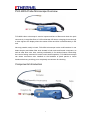
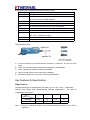
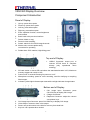
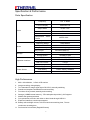
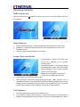
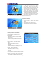
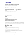
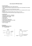
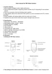
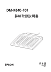
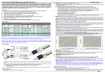
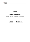
FIBER VANGUARD
—— FVO-600A-V Fiber Microscope
USER MANUAL
Thank you for purchasing the FVO-600A-V microscope.
AUSBEST is the trademark of W&L Development Pty,Ltd, an Australia company which
permits Eternal Co.,Ltd to manufacture and sell the serious products in china mainland.
And Eternal co.,ltd has all products rights reserve.
Please read carefully the user manual before operating, which can be of great help.
This product is controlled by microprocessor, improper use may cause
the monitor stop operating. Please read the manual carefully to enjoy
the performance.
If battery is not fully charged, this may cause serious system error
when recording and transferring video files
Do not open the cover!
It may cause electrical shock
Touch DC convert parts may cause electrical shock
In order to prevent improper operation of DC converter, please read user manual
carefully.
Prevent this product from water and liquid, otherwise, electrical shock and fire danger
may occur.
For you safety, please use only the DC converter provided. ( The manufacturer will not
responsible for any losses caused by DC converter not provided by the manufacturer )
!! Important !!
Please only use the socket matched with DC converter. Use of improper socket may
cause electrical and fire damage.
Please firmly plug the DC converter into the AC socket panel.
A.
B.
C.
Do not use damaged battery
Do not use battery over the specified time period
First use or the battery has not been for past several months, please recharge the
battery before use.
D. In order to protect your battery, please fully charge the battery before use. The
battery must be fully discharge it before you charge it again.
E. Over charge and over discharge will shorten the life of battery
F. If the usage period of fully charged battery is shorten than new battery, you need to
change your battery
G. Battery is consumable item, its life will be shorten from the time it is being used.
H. Don’t let the DC converter with conductors have short circuit, otherwise electrical or
fire damage may occur.
CONTENT
FVO-600A Probe Microscope Overview............................................................................. 1
Components Introduction.................................................................................................... 1
Major Structure............................................................................................................. 2
Inspection Lens............................................................................................................ 2
Barrel Assembly........................................................................................................... 2
Inspection Tips............................................................................................................. 2
Key Features & Specification.............................................................................................. 3
Magnification....................................................................................................................... 3
Resolution.................................................................................................................... 4
Enlarged Zones............................................................................................................ 4
Specification................................................................................................................. 4
Major Function..................................................................................................................... 4
VSM-360 Display Overview................................................................................................. 5
Component Introduction...................................................................................................... 5
Panel of Display........................................................................................................... 5
Bottom end of Display.................................................................................................. 5
Specification & Performance............................................................................................... 6
Parts Specification........................................................................................................6
High Performance........................................................................................................ 6
Operating Guideline............................................................................................................ 7
Mode Introduction.........................................................................................................7
Image Check and Record............................................................................................. 7
Files Playback.............................................................................................................. 7
Systems Setting........................................................................................................... 8
Software Introduction...........................................................................................................9
Video Capture Software............................................................................................... 9
Video Converter Software............................................................................................ 9
FVO-600A-V Microscope Installation................................................................................ 10
Product Accessories.......................................................................................................... 11
Warranty Information......................................................................................................... 11
FVO-600A Probe Microscope Overview
FVO-600A video microscope is used to inspect end-face of fibers and check the optic
connectivity. It magnifies fibers of 125um diameter 650 times, enlarging picture through
a video signal to the display where the status of fiber end-face is showed clearly in the
end.
Not only portable, easily in-hand, FVO-600A microscope is also multi-functional. It can
detect simplex and ribbon fiber ends located in both male and female connectors, as
well as other fiber units. Also, working comfortably is it’s another feature. Eliminating
the need to finding solutions for hard-to-reach areas inspection, FVO-600A microscope
can detect connectors even installed on the backside of patch panels or inside
hardware devices, providing you a completely convenience for checking.
Components Introduction
1
Major Structure
A.
Handle Body: the handle houses many things, like CCD camera, ray apparatus
structure, optical routine system, coaxial lamp-house, focus control, video output
and power supply system et. Also have a PAL signal system.
B.
The Inner Structure of Handle is so compact and complex that, if long time work it
will cause a fever. This isn’t the mechanical faulty but normal phenomena. It may
cause damage if disassemble without permission, which you may also fail to have
troubleshooting.
Inspection Lens
A.
Optical magnification system locates in the front of handle body, the beginning of
which comes a lens-bar.
B.
The Barrel Assembly, mounted on body outside the lens-bar, can match different
types of tips. The lens-bar will be adjusted according to the focus control.
Note: It may cost a lot if the lens or lens-bar is damaged, which have the image formed
and be the cores of probes.
Barrel Assembly
Barrel Assembly plays a vital role in connecting or matching different types of tips.
Note: It will have a serious effect on the image performance once the inner conical
surface from the barrel assembly is hit or impacted.
Inspection Tips
There are specific tips interchangeable for different types of connectors, which allow
you to inspect the fiber surface whether on the backside of the patch panels or inside
hard devices such hard-to-reach areas.
We provide tips of standard and optional types as follow:
Standard Tips:
Optional Tips:
2
More optional tips can be provided as the following table:
Tips
Description
FC/SC-F
to inspect female fiber ends through FC/SC adaptors
LC/MU-F
to inspect female fiber ends especially in the high-density
connector through LC/MU adaptors
FC-APC-F
to inspect APC female fiber ends through FC adapters
SC-APC-F
to inspect APC female fiber ends through SC adapters
ST-F
to inspect female fiber ends through ST adaptors
MU-F
to inspect female fiber ends through MU adaptors
E2000-F
to inspect female fiber ends through E2000 adaptors
2.5PC-M
to inspect PC fiber ends of 2.5mm ferrules directly (normally
SC,FC,ST , E2000 four types)
1.25PC-M
to inspect PC fiber ends of 1.25mm ferrules directly
2.5APC-M
to inspect APC fiber ends of 2.5mm ferrules directly
Tips Installation Note:
A.
B.
C.
D.
E.
Conical surfaces of tips should be well protected, if crushed or hit, can’t be used
again.
Mare sure conical surfaces of tips clean enough prior to installation.
Have a strong tips attachment during installation.
Have a proper screw on the nuts during installation.
Mind the tip before removal of the nut during disassemble.
Key Features & Specification
Magnification
The optical and picture magnification can reach up to 12× and 650× respectively.
Different size display has correspondingly different magnification , the table of
magnification is as below:
Display
Index
2.5 IN.
3.5 IN.
5.6 IN.
9 IN.
Diameter
1.857
2.5
4.5
8.1
Magnification
150
200
360
650
Note: 1.The size of enlarged picture is the measured directly based on the 1.25um
resolution.
3
2.The magnification is calculated by the following equation:
Enlarged size (um)÷1.25um = M
Resolution
The resolution of the probe can reach up to 1.25um whereas
the national standard is only 2um.
Standard Noyes Fiber Calibrated Scale
Enlarged Zones
The enlarged size for the ferrule diameter can reach up to 0.30*0.28mm, Also the most
visible area can reach up to 0.6*0.57mm when adjusting the probe.
Specification
Size
18.6*5.2*5.0MM
Weight
170.00G
Resolution
1.25μm
Optical Magnification
12X
Viewable area
0.3MM*0.28MM
Electronic viewfinder
1/3IN black-and-white CCD
Light Source
BLUE-LED(100000hrs above)
Focus Control
Manual coaxial focus
Connector
4PIN
Operating Temperature
-20℃--50℃
Guarantee period
One year
Major Function
To inspect fiber ends of both simplex and ribbon types
1.
2.
3.
To inspect male fiber ends, which refer to the end of patch cords or pigtails.
To inspect female fiber ends, which refer to the end of port through adapters or
inside devices.
To inspect ferrules of both 2.5 mm and 1.25mm diameters, fixed in the middle of
the fiber. Exposed ones are excluded in the test.
To output PAL or NTSC video signal of the enlarged fiber image
4
VSM-360 Display Overview
Component Introduction
Panel of Display
1.
2.
3.
4.
5.
Up key: press when option
Down key: press when option
Left key: press when option
Right key: press when option
Enter: operation function, control brightness
and contrast
6. Back: back to the previous interface
7. Delete: delete or copy
8. Record: video recording
9. Switch: switch for CH1/CH2 image channels
10. Monitor slot: to mount probe easily,
convenient for operating
11. Rubber boot: PVC material, High falling-proof
Top end of Display
1.
2.
3.
4.
5.
USB2.0 Connector: output port, to
connect OTG/U desk or computer
directly (only operational when
entering).
SD card socket: to house SD card where the standard allocation is 2G, Maximum
memory support can reach to 16G.
Power on/off: 3 seconds Pressing for power on or off.
Microphone recording: press for voice recording, used for clarifying or compiling
fiber images.
Indicator: yellow light indicates open-state while red light indicates charged-state.
Bottom end of Display
1.
4.
5.
6.
7.
CH1 Image Input: Connector: press
CH1/CH2 key to display CH1 image.
2. Charger Connector.
3. Earphone Connector: adjust the volume
via up/down keys.
CH2 Image Input Connector: press CH1/CH2 key to display CH2 image.
Video Output: connect to have voice output.
Reset: can put slim sticks in the hole for recovery from dead halt.
Key lock: can’t operate when locked.
5
Specification & Performance
Parts Specification
Video
Frequency
FM 2.4MHz
2.5 Inch Display
960x240 LCD
Output Mode
NTSC / PAL
Video Mode
NTSC / PAL
Resolution
640*480 / 320*240
Compressed
Format
Audio
Video
Playing Format
MPEG-4/ AVI/ASF/MOV
Frequency Range
20HZ-20KHz
Output Channel
Stereo
Earphone Output
L 20MW+R 20mW [16O](Max volume)
Play Format
Storage
Operation Interface
MP3/WAV/MPEG-1
Size
128MB/1GB
Storage Media
SD/MMC/U disk
IBM-PC
Windows 98SE.ME.2000,XP
USB
USB 2.0; USB OTG2.0
Disk File Format
FAT32
Language
Chinese/English
Power Supply
Power Source
MPEG-4/AVI
DC 5V 2A
Inner Battery
Lithium battery 1800Mah
Media
≥8 hours
High Performance
1.
2.
3.
4.
5.
6.
7.
8.
9.
10.
960 x 240 definition , 2.5inch LCD monitor
Image recording, timing display
Two channels for image signal input CH1/CH2, manually switching
Sensitive microphone installed for sound recording
Functions of key-locked ,stand-by and recording
Storage (128MB internal memory、SD card optional provided ),16G support
Mobile disk optional provided
Can upload files of music and video or other kinds through USB 2.0
Earphone interface, sound output support
Battery safe and high volume, ≥9 hours continuous working time, 7 hours
continuous recording time.
11. Dual version for interface (English/Chinese)
6
Operating Guideline
Mode Introduction
Hold the Power button
the interface.
On/Off for 3 Seconds to turn on or off the monitor and enter
Mode Selection:
1.
2.
3.
Image Check and Record – Check and Record video signals form CH1or CH2
Play Back – Video Recorded File Playback, from Internal Memory, SD Card or
Portable Disk etc.
Setting – System Preset for Different Functions
Image Check and Record
1.
3.
4.
Press [Enter] to check the image from
CH1or CH2 detected by the probes.
Please be sure
2. Press [Enter] again if necessary to adjust
the brightness/ contrast, control the proper
range viaup/down keys. Please note that
color is no need to adjust.
Brightness: the suitable value will be 6.
Contrast: the suitable value will be 4.
When finished, press [Enter] again to exit.
Press [Record] to record the being image and timing, When working, voice is
recorded at the same time, which can be used as indentifying different files. Press
left/right keys to control the recording speed, Press up/down keys to control the
volume. When finished, press [ Back] to exit (shown as picture above)
Files Playback
1.
2.
Press the right key to choose the PLAYBACK mode.
Press [Enter] to see the files recorded. ( need to pre-set first to choose the files
whether from Nandflash(internal memory), SD card or U disk(portable disk). When
7
5.
no SD card or U disk, files are shown
from system. When having SD card or
portable disk but no setting before, files
are shown from SD card automatically )
3. When entered, press up/down keys to
choose files labeled. When opened,
press [Enter] to stop the video to observe,
or files will be displayed continuously.
4. Press [Delete] to decide to delete or copy
files recorded, Press [Enter] to confirm.
When finished, press [Back] to exit.(as pictures shown above)
Systems Setting
1.
2.
3.
Setting Options Available
Record Setting– set before record
and playback
- NandFlash (internal memory,128MB)
- 2G SD Card
- External HDD (portable disk for option)
Memory Status – check the memory
state
- NandFlash (internal memory)
- SD Card
- External HDD (will not display if no use)
Format – memory formatting
- NandFlash (internal memory)
- SD Card
( once confirmed, all the data will be deleted )
System Time Setting– date and time setting
(pre-setting is suggested when first use)
8
Press [Enter] to choose the setting
option.
Press arrow keys to make choice.
Press [Enter] to confirm and operate.
Displaying Setting
- TV-PAL Output: output the video signal on TV through PAL mode.
- TV-NTSC Output: output the video signal on TV through NTSC mode.
- LCD Output: output the video signal through LCD display.
Brightness– press the key to control the brightness
Press the left key to decrease Brightness, Press the right key to increase Brightness
Language– choose the language provided
Default– system reduction
- Chinese
- yes
- English
- no
(more languages will be provided after updating)
Software Introduction
Two types of software are set in the SD card for video capture and converter use.
Video Capture Software
Application:
Capture the video recorded in the microscope, form into the single-frame picture used
as copywriter or paper report.
Running Step:
·Click StormPlayer.exe to install the software on your PC.
·Connect the wire from the microscope to the PC.
·Open the software, choose :file—open files — view , choose video files recorded from
the SD card or internal memory form the microscope.
·To capture the single frame picture, click the spacebar to pause the video, then choose:
file—save as, rename the file and save the picture in JPEG format or BMP
format
(defaulted).
Video Converter Software
Application:
Transfer the video files into microscope display for entertainment
Running Step:
·Click the BlazeVideoMagic.Exe to install the software on your PC.
·Click the KeyMaker.Exe to acquire the register code for installation.
·Run the software: open the local video file, set the output mode and storage path.
·Click Start to convert files.
·Transfer the files into SD card for microscope display.
9
FVO-600A-V Microscope Installation
1.
2.
3.
4.
Attach the barrel assembly to the probe.
Attach the proper inspection tip to the end of barrel assembly.
Insert the probe into repository to inspect the fiber end.
Adjust the focus control to centralize the image on the display if necessary.
Note:
Probes can be mounted on the monitor slot right beside rubber boot ( as picture
shown below ), convenient for single operation.
Mount the probe into VSM-360 Display
through the monitor slot
10
Product Accessories
NO.
Name
Quality
1
DC5V 2A charger
1 pcs
2
User manual
1 pcs
3
USB PC wire
1 pcs
4
AV output wire
1 pcs
5
Earphone
1 pcs
6
Lthium battery(inner)4500MA
1 pcs
Warranty Information
Thanks for your using, Eternal Co.,Ltd will warrant this equipment against defects in
material and workmanship for a period of one year from the date of original shipment.
During the warranty period, any repair, replace for the defective products are free of
charge except the damage by unauthorized or non-Eternal personnel.
Also all the product accessories information is subject to the Eternal Co.,Ltd, it may
change with need without notice, please contact relevant staffs for consult if necessary.
11