1
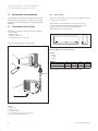
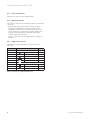
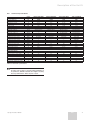
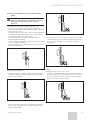
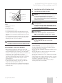
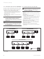
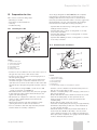
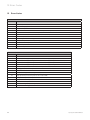
climaVAIR
VAM 2-050 W2N
VAM 2-060 W2N
VAM 2-085 W3N
VAM 2-110 W4N
DE, EN, HR, IT, TR
For the fitter
Installation Manual
Air-conditioner - climaVAIR
Split Type
VAM 2-050 W2N
VAM 2-060 W2N
VAM 2-085 W3N
VAM 2-110 W4N
EN
Contents
Contents
1
1.1
1.2
Your Safety . . . . . . . . . . . . . . . . . . . . . . . . . . . . .3
Symbols used . . . . . . . . . . . . . . . . . . . . . . . . . . . . . . . 3
Correct Use of the Unit . . . . . . . . . . . . . . . . . . . . . . . 3
2
Extreme Operating Conditions . . . . . . . . . . . . . .3
12
12.1
12.2
12.3
12.4
Preparation for Use . . . . . . . . . . . . . . . . . . . . . . 19
Checking for Leaks . . . . . . . . . . . . . . . . . . . . . . . . . 19
Evacuating the Installation . . . . . . . . . . . . . . . . . . . 19
Start Up . . . . . . . . . . . . . . . . . . . . . . . . . . . . . . . . . . . 20
Troubleshooting . . . . . . . . . . . . . . . . . . . . . . . . . . . . .21
3
Identification of the Unit . . . . . . . . . . . . . . . . . .3
13
Error Codes . . . . . . . . . . . . . . . . . . . . . . . . . . . 22
4
Declaration of Conformity . . . . . . . . . . . . . . . . 4
5
5.1
5.2
5.3
5.4
5.5
5.6
Description of the Unit . . . . . . . . . . . . . . . . . . . 4
Indoor Unit . . . . . . . . . . . . . . . . . . . . . . . . . . . . . . . . . 4
Outdoor Unit . . . . . . . . . . . . . . . . . . . . . . . . . . . . . . . . 5
Infra red Controller . . . . . . . . . . . . . . . . . . . . . . . . . . 6
Valve connections . . . . . . . . . . . . . . . . . . . . . . . . . . . 6
Supplied accessories . . . . . . . . . . . . . . . . . . . . . . . . . 6
Technical Specifications . . . . . . . . . . . . . . . . . . . . . . 7
6
Transport . . . . . . . . . . . . . . . . . . . . . . . . . . . . . . 8
7
Unpacking . . . . . . . . . . . . . . . . . . . . . . . . . . . . . 8
8
8.1
8.2
8.3
Installation. . . . . . . . . . . . . . . . . . . . . . . . . . . . . 8
Qualification of the Installation Personnel . . . . . . 8
General precautions to be taken into account
before starting the installation . . . . . . . . . . . . . . . . 8
General Installation Diagram . . . . . . . . . . . . . . . . . . 9
9
9.1
9.2
9.3
9.3.1
9.3.2
9.3.3
9.3.4
9.3.5
9.3.6
Installation of the Indoor Unit . . . . . . . . . . . . . 9
Selecting the Indoor Unit Location. . . . . . . . . . . . . 9
Fixing the Assembly Plate . . . . . . . . . . . . . . . . . . . . 9
Installation of the Pipe Work . . . . . . . . . . . . . . . . . 10
Correct Removal of the Condensate Water. . . . . 10
Handling the Refrigerant Pipes . . . . . . . . . . . . . . . 10
Correct installation of the condensate pipe work . . 11
Making Holes for the Pipes . . . . . . . . . . . . . . . . . . .12
Correct installation of the refrigerant pipe work .12
Installation of the Indoor Unit Body . . . . . . . . . . . .13
10
10.1
10.2
10.3
10.4
Installation of the Outdoor Unit . . . . . . . . . . . 13
Selecting the Assembly Location . . . . . . . . . . . . . .13
Planning the Refrigerant Return . . . . . . . . . . . . . . 14
Connection of the Refrigerant Pipe Work . . . . . . 14
Connection of the Pipe for the Removal of
Condensate Water . . . . . . . . . . . . . . . . . . . . . . . . . . .15
11
11.1
11.2
11.3
11.4
11.5
Electric Wiring . . . . . . . . . . . . . . . . . . . . . . . . . . 15
Safety Precautions. . . . . . . . . . . . . . . . . . . . . . . . . . .15
Remark with regard to Directive 2004/108/CE . . . 16
Electric Connection to the Indoor Unit . . . . . . . . 16
Electric Connection to the Outdoor Unit . . . . . . . .17
Electrical Characteristics . . . . . . . . . . . . . . . . . . . . 18
2
Split Type Installation Manual
Your Safety 1
Extreme operating conditions 2
Identification of the Unit 3
1
Your Safety
1.1
Symbols used
Note!
The relevant personnel performing any service of
maintenance operations involving the handling of
the refrigerant fluid must have the necessary
certification to comply with all local and
international regulations.
Danger!
Direct danger for life and health.
Danger!
Danger of electric shock.
Warning!
Potentially dangerous situation for the product
and the environment.
2
Extreme Operating Conditions
This unit has been designed to operate within the range
of temperatures indicated on Figure 2.1. Ensure that
these ranges are not exceeded.
C
ROOLING
EFRIGERACIÓN
Outdoor
Exterior
Note!
Useful information and indications.
H
EATING
CALEFACCIÓN
45ºC
43ºCD.B.
D.B.
24ºC
24ºCD.B.
D.B.
0ºC D.B.
18ºC
D.B.
-15ºC D.B.
-7ºC D.B.
1.2
Correct Use of the Unit
Indoor
Interior
This unit has been designed and manufactured for the
sole purpose of comfort cooling and heating occupied
residential and commercial premises. The use thereof
for other domestic or industrial purposes shall be the
exclusive responsibility of the persons specifying,
installing or using them in that way.
30ºC
32ºCD.B.
D.B.
30ºC
30ºCD.B.
D.B.
17ºC
D.B.
18ºC
D.B.
17ºC
15ºCD.B.
D.B.
Fig. 2.1 Operating ranges of the unit.
Prior to handling, installing, start up, using or
performing maintenance on the unit, the persons
assigned to perform these tasks should be familiar with
all the instructions and recommendations set forth in
the unit's installation manual.
Legend
D.B. Temperature measured by dry bulb
Note!
The working capacity of the unit changes
depending on the working temperature range of
the outdoor unit.
Note!
Keep the manuals throughout the service life of
the unit.
Note!
The information relating to this unit is divided between
two manuals: installation manual and user manual.
Note!
This equipment contains R-410A refrigerant. Do
not vent R-410A into atmosphere: R-410A, is a
fluorinated greenhouse gas, covered by Kyoto
Protocol, with a Global Warming Potential (GWP)
= 1975.
3
Identification of the Unit
This manual is valid for the Split system series. In order
to know the specific model of your unit please refer to
the unit nameplates.
The nameplates are located on the outdoor and indoor
units.
Note!
The refrigerant fluid contained in this
equipment must be properly recovered for
recycling, reclamation or destruction before
the final disposal of the equipment.
Split Type Installation Manual
EN
3
4 Declaration of Conformity
5 Description of the Unit
4
Declaration of Conformity
The manufacturer declares that this unit has been
designed and constructed in compliance with the
standard in force with regard to obtaining the CE
Marking.
5
Description of the Unit
5.1
Indoor Unit
The indoor unit heats and cools air to be supplied to the
room to be conditioned.
The dimensions and weights of the indoor unit are
shown on Figure 5.2 and Table 5.1, depending on the
model (please consult the model nameplate).
The dimensions are given in mm.
This unit is comprised of the following elements:
- Indoor unit.
- Outdoor unit.
- Remote controller.
- Connections and accessories.
Figure 5.1 shows the unit components.
Fig. 5.2 Dimensions of the indoor unit.
Legend
H Height
L Length
D Depth
MODEL
VAI 2-025 WNI
VAI 2-035 WNI
H
265
L
790
D
200
kg
8,5
265
790
200
8,5
Table 5.1 Dimensions and weights of the indoor unit.
Fig. 5.1 Unit components.
Legend
1 Indoor Unit
2 Outdoor Unit
3 Remote controller
4 Interconnecting pipework (not supplied)
5 Condensed water drainage pipe
4
Split Type Installation Manual
Description of the Unit 5
5.2
Outdoor Unit
The outdoor unit ensures that the absorbed heat is
released to the outside from the room during operation
in cooling mode and that the heat introduced into the
room during operation in heat pump mode is taken from
the outside.
The dimensions and weights of the outdoor unit are
shown on Figure 5.3 and Table 5.2, depending on the
model (please consult the model nameplate).
The dimensions are given in mm.
Fig. 5.3 Dimensions of the outdoor unit.
Legend
H Height
L Length
D Depth
A Length of valves
B Distance between valves
C Distance from the second valve to the floor
F Distance from the third valve to the floor
I Distance between fixing holes
J Distance between fixing supports
MODEL
VAF 2-060 W2NO
VAF 2-085 W3NO
VAF 2-085 W4NO
H
695
695
860
L
845
845
895
D
315
315
330
A
60
60
60
B
60
60
60
C
160
160
160
F
220
220
220
I
335
335
340
J
560
560
590
kg
60
62
78
Table 5.2 Dimensions and weights of the outdoor unit.
Split Type Installation Manual
EN
5
5 Description of the Unit
5.3
Infra red Controller
The remote control allows using the unit.
5.4
Valve Connections
This outdoor unit has the following connections and shut
off valves:
- Gas (G) and liquid connections (L): they carry the
refrigerant between the outdoor and indoor unit.
- Discharge connections for condensate water (in the
outdoor and indoor unit): they allow the water to be
properly discharged which condenses during the
normal operation of the unit.
- Electric connections: these supply electric energy to
the unit.
5.5
Supplied Accessories
This unit is provided with the accessories shown on
Table 5.3.
No.
Accessory
Quantity
Indoor Unit
1
Remote control
1
2
Remote control bracket
1
3
Batteries
2
4
Mounting plate
1
5
Drain tubes
1
Outdoor Unit
1
Cushion
4
2
Drain elbow
1
3
Rubber Cap
2
Table 5.3 Accessories supplied with the unit.
6
Split Type Installation Manual
Description of the Unit 5
5.6
Technical Specifications
Power supply
Cooling Capacity
Power input
Operating current
Heating Capacity
Power input
Operating current
Indoor Unit
Air Flow volume 1
Air Flow volume 2
Air Flow volume 3
Air Flow volume 4
Sound Pressure level 1
Sound Pressure level 2
Sound Pressure level 3
Sound Pressure level 4
Outdoor Unit
Air Flow volume
Sound Pressure level
Refrigerant
Refrigerant charge
Compressor type
Expansion system
Pipe Connections
Diameter liquid/gas pipes
Max. L1 + L2 + (L3) + (L4)
Max. L1
Max. height IU under OU
Max. height OU under IU
Chargeless length
Additional charge per metre
Units
V/Ph/Hz
kW
kW
A
kW
kW
A
VAM 2-050 W2N
7,00
6,10
1,67
7,30
7,20
6,25
1,73
7,50
10,80
9,05
2,49
10,80
12,10
10,10
2,78
12,10
m3/h
m3/h
m3/h
m3/h
dB(A)
dB(A)
dB(A)
dB(A)
250/300/500
250/300/500
/
/
26/32/38
26/32/38
/
/
250/300/500
310/450/580
/
/
26/32/38
28/35/40
/
/
250/300/500
250/300/500
310/450/580
/
26/32/38
26/32/38
28/35/40
/
250/300/500
250/300/500
250/300/500
310/450/580
26/32/38
26/32/38
26/32/38
28/35/40
m3/h
dB(A)
2500
52
2500
52
2500
55
3500
57
gr
1450
1450
2000
2400
1/4" - 3/8"
45
15
10
10
7,5
15
1/4" - 3/8"
60
15
10
10
7,5
15
5,20
1,62
VAM 2-060 W2N
VAM 2-085 W3N
230/1/50
5,40
8,10
1,66
2,48
VAM 2-110 W4N
9,10
2,78
R410A
Rotary
EXV + Capillary
Inches
m
m
m
m
m
gr
1/4" - 3/8"
30
15
10
10
7,5
15
1/4" - 3/8"
30
15
10
10
7,5
15
Table 5.4 Technical specifications.
Note!
As part of its policy for ongoing improvements of
its products, Vaillant reserves the right to modify
these specifications without prior notice.
Split Type Installation Manual
EN
7
6 Transport
7 Unpacking
8 Installation
6
7
Transport
8
Installation
Danger of injury and physical damage!
During transport and unloading, the unit could
fall and injure anyone within the immediate
vicinity. To avoid this:
- Only use transport and lifting gear with
suitable load capacity for the unit weight.
- Use only the transport and lifting gear
correctly (consult the respective user
manuals).
- Use the slinging points provided for this
purpose on the unit.
- Secure the unit correctly using propriety
fixings in the mounting points provided.
- Always use suitable personal protection
equipment (helmet, gloves, safety boots and
protective glasses).
8.1
Qualification of the Installation Personnel
Unpacking
Danger of injury and physical damage!
During unpacking you could get cut and bruised.
To avoid this:
- Use lifting gear with suitable load capacity
for the unit weight.
- Only use the transport and lifting gear
correctly (consult the respective user
manuals).
- Use the slinging points provided for this
purpose on the unit.
- Always use suitable personal protection
equipment (helmet, gloves, safety boots and
protective glasses).
Unpack the unit and check that:
- All parts have been supplied with the system.
- All the parts and accessories are in perfect condition.
If parts are damaged or missing please contact your
supplier immediately.
Warning!
Protect the environment. Dispose of the
packaging following the local
environmental standards in force. Do not dispose
of packaging irresponsibly, recycle where
possible.
8
Ensure that this unit is installed by suitable qualified
personnel.
All installers must hold a suitable safe handling of
refrigerants qualification.
8.2
General precautions to be taken into account
before starting the installation
Danger of injury and physical damage!
During unpacking you could get cut and bruised.
To avoid this:
- Only use lifting gear with suitable load
capacity for the unit weight.
- Use the transport and lifting gear correctly
(consult the respective user manuals).
- Use the slinging points provided for this
purpose on the unit.
- Always use suitable personal protection
equipment (helmet, gloves, safety boots and
protective glasses).
Danger of injury and physical damage!
The unit should be installed in accordance with
the Regulations and Standards for refrigeration,
electrical and mechanical installation pertaining
to the country in which the installation is being
undertaken.
Danger!
Danger of electric shock. All appliances must be
earthed.
Connect the earth cable to the correct earthing
point (do not connect to the gas pipe, water
pipe, lightning conductor or telephone line).
Danger!
Danger of electric shock.
Ensure the appliance is protected by a correctly
rated circuit breaker.
Warning!
Danger of breakdowns or malfunction.
Only use the pipework specifically intended for
refrigerant R410A for the air conditioning
installation. Never use plumbing pipes.
Split Type Installation Manual
Installation 8
Installation of the indoor unit 9
8.3
General Installation Diagram
9
Installation of the Indoor Unit
Warning!
Danger of breakdowns or malfunction.
Observe the minimum clearences indicated in
Figure 8.1.
9.1
Selecting the Clearance Location
Warning!
Danger of breakdowns or malfunction.
Observe the minimum clearances indicated in
Figure 8.1.
Note!
If a hole already exists in the wall or a refrigerant
pipe or condensed water pipe has already been
installed, the base plate can be mounted to adapt
to these conditions.
Recommendations
- Install the indoor unit close to the ceiling,ensuring
minimum clearances are met.
- Choose a position site that will allow air to reach all
parts of the room evenly. Avoid beams, obstructions or
lights which would interfere with the airflow.
- Install the indoor unit at an adequate distance from
chairs or workstations in order to avoid unpleasant
draughts.
- Avoid installing close heat sources.
9.2
Fixing the Mounting Plate
Carry out the steps described below:
• Place the mounting plate on the chosen installation
point.
• Level the plate horizontally and mark the position of
holes to be made on the wall.
• Remove the plate.
Fig. 8.1 General diagram of the installation and the minimum
assembly distances.
Legend
1 Indoor Unit
2 Outdoor Unit
3 Condensate connection for outdoor unit
A Clearance to the front of the internal unit (minimum 10 cm)
B Clearance to ceiling above (minimum 5 cm)
D Height in relation to the floor (minimum 2 m)
E Side clearance opposite side connections (minimum 20 cm)
F Rear clearance (minimum 20 cm)
G Side clearance connections side (minimum 30 cm)
H Front clearance (minimum 100 cm)
Split Type Installation Manual
Warning!
Danger of breaks in the domestic installation.
Check that there are no electricity lines, pipes or
any other services which could be damaged
behind the spots where the holes are to be
drilled.
If other services are found, choose another
installation location and repeat the
aforementioned steps.
• Make the holes using a drill and insert the wall plugs .
• Place the mounting plate in position, level it
horizontally and fix it with the screws and the plugs.
Warning!
Danger of breakdowns or malfunction.
Ensure that the mounting plate has been
correctly levelled. Otherwise, disassemble the
plate and assemble it again correctly. Failure to
do so could lead to water leaks.
EN
9
9 Installation of the indoor unit
9.3
Installation of the Pipe Work
9.3.1 Correct Removal of Condensate Water
Warning!
Danger of breakdowns or malfunction. Danger of
condensed water leakage.
In order to ensure that the unit drains correctly
take the recommendations described in this
section into account.
Methods for the removal of the condensed water which
is generated in the indoor unit:
- Condensed water can be allowed to drain naturally
using the natural fall of the condensed water pipe to a
suitable drain point. In order for it to be aesthetically
pleasing, use a solid pipework or trunking to cover the
pipework.
- Alternative hidden installation solutions also exist.
- For example, using an external pump for removal of
the condensed water, carrying the condensed water to
outside or to main drainage system.
- By natural fall to a collection point which is then
emptied using a pump which operates when the tank
is full, pumping the water to a suitable drain point.
Note!
This pump for condensed water is available as an
original Vaillant accessory with the
corresponding installation instructions (not
supplied in the UK).
Warning!
Danger of breakdowns or malfunction. Danger of
condensed water leakage.
To ensure that the unit drains properly using a
natural fall, the condensed water pipe must have
a an adequate fall from the indoor unit.
10
9.3.2 Handling the Refrigerant Pipes
Danger!
Danger of burns and eye injuries.
When brazing or soldering pipe lines, use
suitable protection equipment (protective eye
protection and mask, welding gloves, flame
proof clothing).
Warning!
Danger of breakdowns or malfunction. Danger of
damage to refrigerant pipes through the use of
unsuitable materials.
- Use only pipes specifically intended for refrigeration
and R410A refrigerant.
Note!
In specialised dealers you will find refrigerant
pipes and the correct thermal insulation.
- Ensure that the refrigerant pipes are clean, dry and
polished on the inside.
- The insulation of the pipes should be done using
specific class ‘O’ insulation for cooling.
- Observe the minimum and maximum pipe lengths for
each model.
- Wherever possible avoid install excessive numbers of
bends in pipes. Do not over bend the pipe, keep the
radius as wide as possible to minimise load losses.
- When brazing pipes together, use only the correct
welding materials. During the brazing process a stream
of dry nitrogen should be run through the inside of the
pipes in order to avoid oxidisation forming inside the
pipe connection.
- Only cut the coolant pipes using propriety pipe cutters,
ensuring no swarf enters the pipe, and always keep the
pipe ends sealed wherever possible.
- Any flaring work should be performed meticulously in
order to create the correct connection and to avoid
subsequent losses of gas through the pipes.
- When reaming the cut pipe keep the pipe opening
directed downwards in order to prevent shavings from
getting into the pipes.
- Mount the joining tubes carefully, ensuring they
cannot become displaced during brazing. Ensure that
there is no strain on the pipe joints.
- Ensure that all pipework is insulated with the correct
grade of closed cell insulation and that all joints in the
insulation are sealed with insulation tape or glued.
- Carefully tighten the flaring connectors, centring the
flaring cone and the flanged nut. Applying excessive
force without correctly centring can damage the
thread and may allow water ingress into the
connection.
Split Type Installation Manual
Installation of the indoor unit 9
9.3.3 Correct Installation of the Condensate Pipe
Work
Warning!
Danger of breakdowns or malfunction. Danger of
water leaks and blockages from unit and
pipework:
- Ensure that sufficient air breaks and traps are
provided to avoid water being retained within the
indoor unit. Otherwise, the condensed water could leak
from the indoor unit.
- For gravity drains ensure fall is sufficient, the pipework
is adequately supported and does not sag and bends
are of large radius to avoid blockages.
- If the water pipe is run outdoors, ensure that it is
insulated against freezing.
- If the condensed water pipe run through an un-heated
room, fit thermal insulation.
- Avoid installing the condensed water pipe with a rising
bend (see Figure 9.2).
Fig. 9.4 Avoid kinking the pipe.
- For drain pipes run to ground level outside, install the
condensed water pipe in such a way that the distance
of its free end from the floor is at least 5 cm (see
Figure 9.5).
Fig. 9.5 Minimum distance from the floor.
Fig. 9.2 Avoid rising bends.
Legend
H Minimum distance from the floor: 5 cm
- If the drain is run to a tank or butt, avoid installing the
condensed water pipe with it free end submerged in
water (see Figure 9.3).
- Install the condensed water pipe in such a way that its
free end is kept away from unpleasant odours, such as
from open drains, to ensure that they are not drawn
back into the unit (see Figure 9.6).
Fig. 9.3 Avoiding submerging the end.
Fig. 9.6 Avoids unpleasant odours.
- Do not allow the drain line to be crimped or flattened
which could reduce the flow of water from the indoor
unit (see Figure 9.4).
Split Type Installation Manual
EN
11
9 Installation of the indoor unit
9.3.4 Making Holes for the Pipes
9.3.5 Correct Installation of Indoor Unit Refrigerant
Pipe Work
• Case A: Pipework exiting from the rear of the unit.
In this case, a suitable hole must be made in the wall
behind the unit (see Figure 9.1).
• Drill a hole in accordance with the diameter and
position as indicated in Figure 9.1, ensure the hole
is slightly descending to the outside to allow for a
fall in the drain line.
025 /035
150 mm or more to ceiling
Indoor unit outline
• If installing the rear exiting piping:
• Place the seal ring supplied for the hole in the piping
and insert the coolant pipes with the condensed
water pipe through the hole.
• Remember to seal the hole inside and out properly
after installing the pipes.
• Carefully bend the installation pipe in the right
direction, taking care not to overbend or kink the pipe.
Installation plate
• Case B: Running the pipework out of either side or the
bottom of the unit.
In this case holes do not have to made in the wall
since the indoor unit body has knock outs which can
be opened to allow the pipes to exit the unit: choose
the most convenient one for the desired outlet
position (see Figure 9.7).
• Carefully break the knock out in the casing using pliers.
• There should be sufficient pipe tails on the indoor unit
to go through the wall width. If this is not the case
connect further lengths of pipe as required. Carefully
feed the pipe tails through the holes together with the
condensate pipework and interconnecting electrical
cable.
• Hang the indoor unit on the top edge of the
mounting plate.
• Tilt the lower part of the indoor unit forwards and
insert an auxiliary tool (e.g. a piece of wood) between
the mounting plate and the unit (see Figure 9.8) to
allow access to the unit connections.
Fig. 9.7 Windows for the installation of the pipes.
Fig. 9.8 Assembling the indoor unit.
Legend
1 Exit for right piping
2 Exit for indoor piping
3 Securing with adhesive tape
4 Exit for left piping
• Connect the coolant pipes from the outdoor unit and
the condensed water hose to the installation drain.
• Insulate the coolant piping and joints correctly and
separately. To do so, cover any possible cuts with
masking tape or insulate any bare coolant piping with
the corresponding insulation material suitable for air
conditioning installations (for connection of the
electrical wiring see section 11).
025: 250 mm
035: 265 mm
Right refrigerant
pipe hole Ø 65
Warning!
Danger of breakdowns or malfunction. Danger of
damage to the coolant pipes.
Bend the pipe carefully to prevent kinking or
breaks.
120mm or
more to
wall
Left refrigerant
pipe hole Ø 65
790 mm
120mm or
more to wall
Fig. 9.1 Dimensions of the hole for the piping.
12
Split Type Installation Manual
Installation of the indoor unit 9
Installation of the outdoor unit 10
10 Installation of the Outdoor Unit
10.1
Selecting the Assembly Location
Warning!
Outdoor units must be placed in accessible areas
for subsequent maintenance and repair
operations. Vaillant will not be responsible for
any costs derived from incorrect positioning that
prevents easy access.
Fig. 9.9 Section showing pipework run behind indoor unit.
Legend
1 Heat-resistant material
2 Drain pipe
3 Coolant pipe
4 Piping support plate
5 Indoor/outdoor electric cable
• For pipework exiting from the right hand side and
bottom of the unit extend the pipework through the
relevant knock out before hanging unit (see section
9.3.6).
• For pipework exiting from the left of the unit, make
the connections at the rear of the unit first before
hanging the unit (see section 9.3.6).
Note!
The flare connections should be, where possible,
accessible to allow leak test and future access.
9.3.6 Installation of the Indoor Unit Body
• Check that the installation has been carried out
correctly and that there are no leaks (see section 12.1).
• Securely hang the indoor unit body onto the upper
notches of the mounting plate. Briefly move the body
from side to side to verify that it is secure.
• Lift the body up slightly from underneath, press it
onto the mounting plate and then lower it vertically.
The body will fit into the lower supports on the
mounting plate.
• Check that the indoor unit is properly secured.
• In the event that the body does not slot into the
supports properly, repeat this process.
• Do not use excessive force as this may damage the
fixing lugs, ensure that the pipework is not trapped
behind the unit.
Split Type Installation Manual
Danger of personal injury and material damage
from explosion!
Install the unit away from inflammable gasses
or liquids or easily combustible substances and
free from thick dust formation.
Danger of personal injury and material damage
from collapse!
Ensure that the ground is smooth and level
and can withstand the weight of the outdoor
unit.
Warning!
Danger of corrosion.
Do not install the unit near to corrosive
materials.
- The outdoor unit can only be mounted outdoors, never
inside a building.
- Do not install the unit in such a way that the air
discharge affects the air inlets of premises nearby.
- If possible avoid direct sunlight.
- Ensure that the ground has sufficient rigidity to avoid
vibrations.
- Ensure that there is sufficient space to observe the
minimum distances (see Figure 8.1).
- Ensure that neighbours are not disturbed by draughts
or noise.
- If the premises are rented obtain the owner's consent.
- Comply with local regulations: there are considerable
differences dependant on the area.
- Leave enough space to fit the condensed water
drainage pipe (see section 10.4).
EN
13
10 Installation of the outdoor unit
10.2 Planning the Refrigerant Return
The refrigerant circuit contains a special oil to lubricate
the outdoor unit compressor. To assist the return of the
oil to the compressor the following is recommended:
- that the indoor unit is located higher than the outdoor
unit and,
- that the suction pipe (the thickest one) is assembled
with a gentle slope towards the compressor.
If the outdoor unit is mounted higher than the indoor
unit, the suction pipe must be mounted in a vertical
position. At heights exceeding 7.5 m (where this is
permissible):
• Additional oil traps must be installed at each 7.5M
interval
10.3
10.4 Connection of the Condensate Drain Pipe to
Outdoor Unit
Note!
Applicable only to heat pump units.
Whilst the unit is running with the heat pump function,
condensation forms in the outdoor unit and has to be
drained.
• Insert the elbow included in the supply in the hole
provided at the bottom of the outdoor unit and turn it
90º to fix it (see Figure 10.2).
Connection of the Refrigerant Pipes
Note!
Installation is easier if the gas suction pipe is
connected up first. The suction pipe is the
thickest one.
• Mount the outdoor unit in the required position.
• Remove the flare nuts and bonnets from the shut off
in the outdoor unit.
• Carefully bend the installed pipe towards the outdoor
unit.
Warning!
Danger of breakdowns or malfunction. Danger of
damage in the refrigerant pipes.
Bend the pipe carefully to prevent kinks or
breaks.
• Cut the pipes, leaving enough extra piping hanging
over to enable the unit to be connected at the outdoor
unit joins.
• Flare the refrigerant pipe after first placing the flare
nut on the pipe.
• Join the refrigerant pipes to the corresponding
outdoor unit connection.
• Insulate the refrigerant piping correctly and
separately. To do so, cover any joins in the insulation
with masking tape or insulate any bare coolant piping
with the corresponding insulation material suitable for
air conditioning.
14
Fig. 10.2 Assembly of the drainage elbow for condensed water
Legend
1 Outdoor Unit
2 Drainage elbow
3 Drainage hose
• Mount the drainage hose ensuring that it leaves the
equipment with a downward slope.
• Verify the correct drainage of the water by pouring
the water into a collection tray located at the bottom
of the outdoor unit.
• Protect the condensate water hose with thermal
insulation to avoid freezing.
Split Type Installation Manual
Installation of the outdoor unit 10
Electric Wiring 11
11
Electric Wiring
11.1
Safety Precautions
Danger!
Danger of electric shock.
Before connecting the unit to the electric
supply line, ensure that the power is isolated.
Danger!
Danger of electric shock.
All electrical works should be completed by an
electrician or a similarly qualified person.
Danger!
Danger of electric shock.
Ensure that the power line is equipped with a
bipolar or tetrapolar switch according to the
model, (single phase or three-phase) with a
distance of at least 3 mm between contacts
(Standard EN-60335-2-40).
Danger!
Danger of electric shock.
Equip the installation with protection against
short-circuits to avoid electric shocks. This is a
legal requirement.
Danger!
Danger of electric shock.
Some units may be supplied with an European
style plug, where this does not match the local
electrical sockets only use with a suitable
adaptor or replace the plug with a UK style one.
Split Type Installation Manual
Danger!
Danger of electric shock.
Use wiring in accordance with the respective
local, national and international wiring
standards regarding installation in technical
electrics.
Danger!
Danger of electric shock.
Use an approved electric plug and power supply
cable.
Warning!
Danger of breakdowns or malfunction.
All electrical wiring must be of suitable size and
rating for the appliance and should only be
installed by suitably qualified personnel.
Warning!
Danger of breakdowns or malfunction.
Compliance with the Standard EN 61000-3-11:
Check that the nominal power of the main phase
current connection is > 100.
Warning!
Danger of breakdowns or malfunction.
Ensure that the supplied power voltage is in the
range of 90% to 110% of the rated voltage.
Warning!
Install the unit in such a way that the electric
plug is easily accessible. Thus, if required, the
unit can be quickly disconnected.
EN
15
11 Electric Wiring
11.2
Remark with regard to Directive 2004/108/CE
11.3
In order to prevent electromagnetic interference during
the start up of the compressor (technical process), the
following installation conditions must be adhered to.
• Make the air conditioning unit power supply
connection at the main power distribution. Carry out
the distribution with low impedance. Normally the
required impedance is reached at a
32 A fusing point.
• Check that no other equipment is connected to this
power supply line.
Warning!
Danger of breakdowns or malfunction. If the fuse
on the PC board is blown please change it
with type T. 3,15A/250V.
Note!
For more detailed information on the electric
installation, please consult the Technical
Connection Conditions applied by your electricity
supply board.
Note!
In order to obtain more information with regard
to power details of the air conditioner consult
the unit rating plate.
Electric Connection to the Indoor Unit
• Open the front panel of the indoor unit by pulling it
upwards.
• Remove the wiring cover on the right of the body by
unscrewing it.
• Insert the cable from the outside:
• Using the same hole through which the coolant pipes
are installed (or are going to be installed later) or,
• Using another of the pipe installation knock outs
provided on the body.
• Pull the electrical cable from the rear of the indoor
unit through to the front of the unit.
• Make the connections on the terminal strip of the
indoor unit according to the corresponding wiring
diagram (see Figure 11.1).
• Check that the cables are properly fixed and
connected, position the wiring cover and mount the
outside body.
VAF 2-060 W2NO
VAF 2-085 W3NO
Outdoor A
Outdoor B
Outdoor A
Outdoor B
Outdoor C
Indoor A
Indoor B
Indoor A
Indoor B
Indoor C
VAF 2-085 W4NO
Outdoor A
Outdoor B
Outdoor C
Outdoor D
Indoor A
Indoor B
Indoor C
Indoor D
= Quick socket
S
L
N
Fig. 11.1 Wiring
16
Split Type Installation Manual
Electric Wiring 11
11.4
Electric Connection to the Outdoor Unit
Warning!
Danger of breakdowns or malfunction. If the fuse
on the PC board is blown please change it
with type T. 25A/250V.
• Remove the protective covering in front of the
electrical connections in the outdoor unit.
• Loosen the screws in the cable retainer and fully
insert the cable ensuring the cable sheath extends
past the cable retainer before tightening the screws to
clamp the cable.
Warning!
Danger of malfunction and breakdowns resulting
from water penetration.
Always terminate the interconnecting cable from
below the cable entry to avoid water penetration
into the terminal box.
Warning!
Danger of malfunction and breakdowns resulting
from short-circuits.
If using a cable with additional cores, insulate
the unused cable wires using electrical tape and
ensure that they cannot come into contact with
any other parts of the electrical installation.
• Check the cable retainer is sufficiently tight to avoid
undue strain on the connections.
• Check that the cables are correctly secured and
connected.
• Replace the protective wiring cover.
Split Type Installation Manual
EN
17
11 Electric Wiring
11.5 Electrical Characteristics
Power supply (V/Ph/Hz)
Supply section up to 25 meter (in mm2)
Supply
Indoor/Outdoor
Thermal-magnetic circuit breaker, type D (A)
VAM 2-050 W2N
VAM 2-060 W2N
VAM 2-085 W3N
VAM 2-110 W4N
230/1/50
230/1/50
230/1/50
230/1/50
2,5
2,5
4
6
Outdoor
Outdoor
Outdoor
Outdoor
16
16
20
25
Interconnection section up to 25 meter (mm2)
Inteconnect shielded cable or not (YES/NO)
Immediatte residual current protector (A)
These units already include an interconnection cable.
NO
NO
NO
NO
0,03
0,03
0,03
0,03
Table 11.1 Electrical Characteristics.
18
Split Type Installation Manual
Preparation for Use 12
12 Preparation for Use
This consists of the following steps:
• Checking for Leaks.
• Evacuation of the installation.
• Start up.
• Troubleshooting.
12.1
Checking for leaks
According to Regulation 842/2006/EC, the complete
refrigerant circuit must be periodically checked for
leakage. Take the necessary actions to ensure these
tests are performed and the results correctly logged into
the maintenance record of the machine. The leakage
test must be done with the following frequency:
• Systems with less than 3 kg of refrigerant => periodic
leakage test not needed
• Systems with 3 kg or more of refrigerant => at least
once every 12 months
• Systems with 30 kg or more of refrigerant => at least
once every 6 months
• Systems with 300 kg or more of refrigerant => at least
once every 3 months
12.2 Evacuating the Installation
Fig. 12.1 Checking for leaks in the installation.
Legend
1 Suction valve (gas)
2 Return valve (liquid)
3 Service manifold
4 Non-return valve
5 Gauge lines
6 Nitrogen cylinder
• Connect a service manifold set to the service port on
the gas line stop valve of the outdoor unit.
• Connect a nitrogen cylinder to the charging hose of
the refrigerant gauges.
• Carefully open the valves on the service manifold to
allow the nitrogen to enter the installation. Do not
open the service valve on the outdoor unit as this will
release the pre-charged refrigerant from the outdoor
unit.
• In the event of using R-410A coolant set it to 40
bar(g) of pressure, for 10/20 min.
• Check that all the connections and joints are gastight.
If any leaks are found, repair and start the process
again from the beginning.
• On satisfactory completion of the test, close all the
valves on the combined meter and remove the
nitrogen cylinder.
• Release the pressure from the system by slowly
opening the valves on the service manifold.
• Do not continue to the next step until the pressure
test has been successfully completed.
Split Type Installation Manual
12.2 Evacuating the installation
Legend
1 Suction valve (gas)
2 Return valve (liquid)
3 Service manifold
4 Non-return joint
5 Gauge lines
6 Vacuum pump suitable for refrigeration systems
• Connect a service manifold to the three-way valve on
the gas line of the outdoor unit.
• Connect a vacuum pump to the charging connection of
the service manifold.
• Ensure that the the service manifold valves are closed.
• Turn the vacuum pump on and open the service
manifold shut off valve to open the system to the
vacuum pump
• Ensure that all other valves are closed.
• Leave the vacuum pump functioning for approximately
15 minutes (depending on the size of the installation)
to carry out the vacuum.
• Check the needle on the low pressure manometer: it
should indicate -0.1 MPa (-76 cmHg - >3 Torr). If the
service manifold gauge is not capable of measuring to
these pressures a separate Torr gauge should be fitted
in line to measure this pressure.
EN
19
12 Preparation for Use
12.3 Start Up
Fig. 12.5 Filling the installation.
Fig. 12.3 Low pressure manometer reading with the low valve
open.
Legend
1 Two-way valve
2 Actuation faucet
• Close the valves on the service manifold and
disconnect the vacuum pump.
• Check the manometer needle after approximately 1015 minutes have elapsed: the pressure should not rise.
If it does rise, there are leaks in the circuit: repair
them (Check all joints and connections to the service
manifold carefully as the leak may be here).
• Close the valves on the service manifold and
disconnect the vacuum pump.
• Open the two-way valve by twisting the allen key 90º
anticlockwise and close it after 6 seconds. The
installation will be filled with coolant.
• Check the installation again for tightness:
• If there are leaks see section 12.4.
• If there are no leaks, continue.
• Remove the service manifold.
• Open the two and three-way service valves by twisting
the allen key anticlockwise as far as it will go.
Warning!
Do not proceed to the next step until a
satisfactory evacuation of the installation has
been completed
Fig. 12.6 Opening of the two and three-way valves.
Legend
1 Two-way shut off valve
2 Three-way service valve
3 Allen key (not supplied) to open valves
• Seal the two and three-way service valves with the
corresponding protective covers.
Fig. 12.4 Low pressure manometer reading with the low valve
closed: checking for leaks.
Warning!
Danger of malfunction and leaks.
Ensure that the service valves on the outdoor
unit are closed.
Fig. 12.7 Protective covers.
20
Split Type Installation Manual
Preparation for Use 12
Legend
1 Service hole lid
2 Two and three-way valve covers
• Connect the unit and run it for a few moments
checking that it carries out its functions correctly (for
more information see the user manual).
12.4 Troubleshooting
If the event of a gas leak, proceed as follows:
• Recover the remaining refrigerant from the system.
- You will need the correct refrigerant recovery unit
and refrigerant reclaim cylinder to achieve this.
Warning!
Never release refrigerant into the environment!
Refrigerant R410A is a harmful product for the
environment.
• Check the flaring joins.
• Repair the leak, replace indoor and outdoor parts
which are the cause of the leak as necessary.
• Fill the unit with the correct weight of refrigerant
using accurate and calibrated electronic scales.
• Proceed to check for leakage as described above.
Split Type Installation Manual
EN
21
13 Error Codes
13
Error Codes
INDOOR UNIT
DISPLAY
LED STATUS
E0
EEPROM parameter error
E2
Zero-crossing signal error
E3
Indoor fan speed out of control
E6
Open or short circuit of indoor room or evaporator temperature sensor
E1
Indoor / outdoor units communication protection
E5
Open or short circuit of outdoor ambient or condenser temperature sensor or outdoor EEPROM parameter error
P0
IPM module protection
P1
Over voltage or too low voltage protection
P2
Temperature protection of compressor top
P3
Compressor current protection
P4
Inverter compressor drive error
P5
Mode conflict protection�for Multi�
OUTDOOR UNIT
DISPLAY
E0
22
LED STATUS
EEPROM error
E1
Nº 1 Indoor units pipe temp. sensor or connector of pipe temp. sensor is defective
E2
Nº 2 Indoor units pipe temp. sensor or connector of pipe temp. sensor is defective
E3
Nº 3 Indoor units pipe temp. sensor or connector of pipe temp. sensor is defective
E6
Nº 4 Indoor units pipe temp. sensor or connector of pipe temp. sensor is defective
E4
Outdoor temp. sensor or connector of temp. sensor is defective
E5
Voltage protection of compressor
E7
Indoor and outdoor communication error
P0
Compressor top protection against temperature
P1
High pressure protection (just for VAF 2-085 W4NO)
P2
Low pressure protection (just for VAF 2-085 W4NO)
P3
Compressor current protection
P4
Inverter module protection
P6
Condenser high-temperature protection
P7
Compressor driving protection
Split Type Installation Manual