1
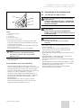
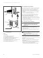
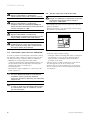
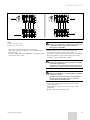
For the fitter
Installation Manual
Air-conditioner - climaVAIR
Split Type
V 7-025NW
V 7-035NW
EN
Contents
Contents
1
1.1
1.2
Your Safety . . . . . . . . . . . . . . . . . . . . . . . . . . . . 3
Symbols used . . . . . . . . . . . . . . . . . . . . . . . . . . . . . . . 3
Proper Use of the Unit . . . . . . . . . . . . . . . . . . . . . . . 3
2
Extreme Operating Conditions. . . . . . . . . . . . . 3
3
Identification of the Unit . . . . . . . . . . . . . . . . . 3
4
Declaration of Conformity . . . . . . . . . . . . . . . . 4
5
5.1
5.2
5.3
5.4
5.5
5.6
Description of the Unit . . . . . . . . . . . . . . . . . . . 4
Indoor Unit . . . . . . . . . . . . . . . . . . . . . . . . . . . . . . . . . 4
Outdoor Unit . . . . . . . . . . . . . . . . . . . . . . . . . . . . . . . . 5
Remote Controller . . . . . . . . . . . . . . . . . . . . . . . . . . . 6
Connections and Channels. . . . . . . . . . . . . . . . . . . . 6
Accessories . . . . . . . . . . . . . . . . . . . . . . . . . . . . . . . . . 6
Technical Specifications . . . . . . . . . . . . . . . . . . . . . . 7
6
Transport . . . . . . . . . . . . . . . . . . . . . . . . . . . . . . 8
7
Unpacking . . . . . . . . . . . . . . . . . . . . . . . . . . . . . 8
8
8.1
8.2
Installation. . . . . . . . . . . . . . . . . . . . . . . . . . . . . 8
Qualification of the Installation Personnel . . . . . . 8
General precautions to be taken into account
before starting the installation . . . . . . . . . . . . . . . . 8
General Installation Diagram . . . . . . . . . . . . . . . . . . 9
8.3
9
9.1
9.2
9.3
9.3.1
9.3.2
9.3.3
9.3.4
9.3.5
9.3.6
10
10.1
10.2
10.3
10.4
11
11.1
11.2
11.3
11.4
11.5
2
12
12.1
12.2
12.3
12.4
Preparation for Use. . . . . . . . . . . . . . . . . . . . . 19
Checking for Leaks . . . . . . . . . . . . . . . . . . . . . . . . . 19
Purging the Installation . . . . . . . . . . . . . . . . . . . . . 19
Start Up . . . . . . . . . . . . . . . . . . . . . . . . . . . . . . . . . . 20
Troubleshooting . . . . . . . . . . . . . . . . . . . . . . . . . . . . 21
Installation of the Indoor Unit . . . . . . . . . . . . . 9
Selecting the Assembly Location . . . . . . . . . . . . . . 9
Fixing the Assembly Plate . . . . . . . . . . . . . . . . . . . . 9
Installation of the Pipes . . . . . . . . . . . . . . . . . . . . . 10
Methods for the Correct Discharge of the
Condensed Water . . . . . . . . . . . . . . . . . . . . . . . . . . . 10
Handling the Coolant Pipes . . . . . . . . . . . . . . . . . . 10
Handling the Condensed Water Pipe . . . . . . . . . . . . 11
Making Holes for the Pipes . . . . . . . . . . . . . . . . . . 12
Laying the Pipes. . . . . . . . . . . . . . . . . . . . . . . . . . . . 12
Installation of the Indoor Unit Body . . . . . . . . . . . 13
Installation of the Outdoor Unit . . . . . . . . . .
Selecting the Assembly Location . . . . . . . . . . . . .
Planning the Coolant Return . . . . . . . . . . . . . . . . .
Connection of the Coolant Pipes . . . . . . . . . . . . .
Connection of the Pipe for the Removal of the
Condensed Water . . . . . . . . . . . . . . . . . . . . . . . . . . .
13
13
14
14
Electric Wiring . . . . . . . . . . . . . . . . . . . . . . . . .
Safety Precautions. . . . . . . . . . . . . . . . . . . . . . . . . .
Remark with regard to Directive 89/336/EEC . . . .
Electric Connection of the Indoor Unit . . . . . . . .
Electric Connection of the Outdoor Unit . . . . . . .
Electric Characteristics . . . . . . . . . . . . . . . . . . . . . .
15
15
16
16
17
18
15
Split Type Installation Manual
Your Safety 1
Extreme operating conditions 2
Identification of the Unit 3
1
Your Safety
2
1.1
Symbols used
This unit has been designed to operate within the range
of temperatures indicated on Figure 2.1. Ensure that
these ranges are not exceeded.
Danger!
Direct danger for life and health.
Extreme Operating Conditions
CROOLING
EFRIGERACIÓN
Danger!
Danger of electric shock.
Outdoor
Exterior
18ºC
18ºCD.B.
D.B.
Note!
Useful information and indications.
This unit has been designed and manufactured for
acclimatisation purposes by means of air conditioning.
The use thereof for other domestic or industrial
purposes shall be the exclusive responsibility of the
persons projecting, installing or using them in that way.
Prior to handling, installing, start up, using or
performing maintenance on the unit, the persons
assigned to perform these tasks should be familiar with
all the instructions and recommendations set forth in
the unit's installation manual.
-7ºC D.B.
-7ºC D.B.
Indoor
Interior
Proper Use of the Unit
43ºC
D.B.
43ºC
D.B.
24ºC
D.B.D.B.
24ºC
Warning!
Potentially dangerous situation for the product
and the environment.
1.2
HCEATING
ALEFACCIÓN
32ºC
D.B.
32ºC
D.B.
30ºC
30ºCD.B.
D.B.
18ºC
D.B.D.B.
18ºC
15ºC
D.B.
15ºC
D.B.
Fig. 2.1 Operating ranges of the unit.
Legend
D.B. Temperature measured by dry bulb
3
Identification of the Unit
This manual is valid for the Split Murales series. In order
to know the specific model of your unit please refer to
the unit nameplates.
The nameplates are located on the outdoor and indoor
units.
Note!
Keep the manuals throughout the service life of
the unit.
Note!
The information relating to this unit is divided
between two manuals: installation manual and
user manual.
Split Type Installation Manual
EN
3
4 Declaration of Conformity
5 Description of the Unit
4
Declaration of Conformity
The manufacturer declares that this unit has been
designed and constructed in compliance with the
standard in force with regard to obtaining the CE
Marking.
5
Description of the Unit
5.1
Indoor Unit
The indoor unit provides acclimatised air inside the
room to be acclimatised.
The dimensions and weights of the indoor unit are
shown on Figure 5.2 and Table 5.1, depending on the
model (please consult the model nameplate).
The dimensions are given in mm.
This unit is comprised of the following elements:
- Indoor unit.
- Outdoor unit.
- Remote controller and holder.
- Connections and channels.
- Accessories.
Figure 5.1 shows the unit components.
Fig. 5.2 Dimensions of the indoor unit.
Legend
H Height
L Length
D Depth
MODEL
V 7-025 NWI
V 7-035 NWI
H
285
285
L
850
850
D
160
160
kg
10
10
Table 5.1 Dimensions and weights of the indoor unit.
Fig. 5.1 Unit components.
Legend
1 Indoor Unit
2 Outdoor Unit
3 Remote controller and holder
4 Connections and channels
5 Condensed water drainage pipe
4
Split Type Installation Manual
Description of the Unit 5
5.2
Outdoor Unit
The outdoor unit ensures that the absorbed air is
released to the outside from the room during operation
in cooling mode and that the heat introduced into the
room during operation in heat pump mode is taken from
the outside.
The dimensions and weights of the outdoor unit are
shown on Figure 5.3 and Table 5.2, depending on the
model (please consult the model nameplate).
The dimensions are given in mm.
Fig. 5.3 Dimensions of the outdoor unit.
Legend
H Height
L Length
D Depth
A Length of valves
B Distance between valves
C Distance from the second valve to the floor
Air inlet
Air outlet
MODEL
V 7-025 NWO
V 7-035 NWO
H
543
543
L
783
783
D
255
255
A
45
45
B
55
55
C
80
80
I
265
265
J
500
500
kg
30
30
Table 5.2 Dimensions and weights of the outdoor unit.
Split Type Installation Manual
EN
5
5 Description of the Unit
5.3
Remote Controller
The remote control allows using the unit.
5.4
Connections and Channels
This unit has the following connections and channels:
- Gas (G) and liquid channels (L): they carry the cooling
agent between the outdoor and indoor unit.
- Discharge channels for condensed water (in the
outdoor and indoor unit): they allow the water to be
properly discharged which condenses during the
normal operation of the unit.
- Electric connections: they supply electric energy to
the unit.
5.5
Accessories
This unit is provided with the accessories shown on
Table 5.3.
No.
Accessory
Quantity
Indoor Unit
1
Remote Control
1
2
Batteries
2
3
Mounting plate
1
4
Drain tubes
1
5
Piping support plate
1
6
Screw - Plastic cap
4
10
User Manual
1
11
Warranty cards
1
1
Cushion
1
2
Drain elbow
1
3
Installation Manual
1
Outdoor Unit
Table 5.3 Accessories supplied with the unit.
6
Split Type Installation Manual
Description of the Unit 5
5.6
Technical Specifications
Power supply
Cooling Capacity
Power input
Operating current
Heating Capacity
Power input
Operating current
Indoor Unit
Air Flow volume
Sound Power level
Sound Pressure level
Sound Pressure level min speed
Dimensions (HxLxD)
Net Weight
Outdoor Unit
Air Flow volume
Sound Power level
Sound Pressure level
Refrigerant
Refrigerant charge
Compressor type
Expansion system
Dimensions (HxLxD)
Net Weight
Pipe Connections
Diameter liquid/gas pipes
Maxi piping length
Max. height IU under OU
Max. height OU under IU
Chargeless lenght
Additional charge per meter
Units
V/Ph/Hz
kW
kW
A
kW
kW
A
V 7-025 NW
2.53
0.74
4.50
3.03
0.75
4.50
3.43
1.07
4.80
3.98
1.10
4.70
m3/h
dB(A)
dB(A)
dB(A)
mm
kg
450
38
35
32
160x850x285
10
450
42
40
38
160x850x285
10
m3/h
dB(A)
dB(A)
2100
55
50
mm
kg
1800
58
50
R410A
700
Rotary
Capillary
543x783x255
30
543x783x255
30
Inches
m
m
m
m
gr
1/4" - 3/8"
15
10
10
5
20
1/4" - 3/8"
15
10
10
5
20
gr
V 7-035 NW
230/1/50
1000
Table 5.4 Technical specifications.
Note!
As part of its policy for ongoing improvements of
its products, Vaillant reserves the right to modify
these specifications without prior notice.
Split Type Installation Manual
EN
7
6 Transport
7 Unpacking
8 Installation
6
7
Transport
8
Installation
Danger of injury and physical damage!
During transport and unloading, the unit could
fall and injure anyone within the immediate
vicinity. To avoid this:
- Use transport and lifting gear with suitable
load capacity for the unit weight.
- Use the transport and lifting gear correctly
(consult the respective user manuals).
- Use the slinging points provided for such a
purpose on the unit.
- Secure the unit correctly.
- Use suitable personal protection equipment
(helmet, gloves, safety boots and protective
glasses).
8.1
Qualification of the Installation Personnel
Unpacking
Danger of injury and physical damage!
During unpacking you could get cut and bruised.
To avoid this:
- Use lifting gear with suitable load capacity
for the unit weight.
- Use the transport and lifting gear correctly
(consult the respective user manuals).
- Use the slinging points provided for such a
purpose on the unit.
- Use suitable personal protection equipment
(helmet, gloves, safety boots and protective
glasses).
Unpack the unit and check that:
- The supply is complete.
- All the elements are in perfect condition.
Failing this, contact the manufacturer.
Warning!
Protect the environment. Dispose of the
packaging following the local standards in force.
Do not dispose of it without the proper controls.
Ensure that this unit is installed by authorised
personnel.
The personnel authorised by Vaillant must be suitably
qualified and able to install the unit correctly.
8.2
General precautions to be taken into account
before starting the installation
Danger of injury and physical damage!
During unpacking you could get cut and bruised.
To avoid this:
- Use lifting gear with suitable load capacity
for the unit weight.
- Use the transport and lifting gear correctly
(consult the respective user manuals).
- Use the slinging points provided for such a
purpose on the unit.
- Use suitable personal protection equipment
(helmet, gloves, safety boots and protective
glasses).
Danger of injury and physical damage!
The unit should be installed in accordance with
the Regulations and Standards for refrigerator,
electrical and mechanical installation prevailing
in relation to the location of such installations.
Danger!
Danger of electric shock.
Connect the earth cable to the right line (not to
the gas pipe, water pipe, lightning conductor or
telephone line).
Danger!
Danger of electric shock.
Install differentials to avoid short-circuits.
Warning!
Danger of breakdowns or malfunction.
Use the pipes specifically intended for coolant
for the cooling installation. Never use plumbing
pipes.
8
Split Type Installation Manual
Installation 8
Installation of the indoor unit 9
8.3
General Installation Diagram
9
Installation of the Indoor Unit
Warning!
Danger of breakdowns or malfunction.
Observe the minimum assembly distances
indicated in Figure 8.1.
9.1
Selecting the Assembly Location
Warning!
Danger of breakdowns or malfunction.
Observe the minimum assembly distances
indicated in Figure 8.1.
Note!
If a hole already exists in the wall or a coolant
pipe or condensed water pipe has already been
installed, the base plate can be mounted to adapt
to these conditions.
Recommendations
- Install the indoor unit close to the ceiling.
- Choose a mounting site that will allow air to reach all
parts of the room evenly. Avoid beams, installations or
lights which obstruct the airflow.
- Install the indoor unit at an adequate distance from
chairs or workstations in order to avoid unpleasant
draughts.
- Avoid close heat sources.
9.2
Fixing the Assembly Plate
Carry out the steps described below:
• Place the mounting plate on the chosen installation
point.
• Level the plate horizontally and mark the holes to be
made on the wall for the installation using the screws
and rawplugs.
• Remove the plate.
Fig. 8.1 General diagram of the installation and the minimum
assembly distances.
Legend
1 Indoor Unit
2 Outdoor Unit
3 Pipe for draining the condensed water
A Front separation (minimum 10 cm)
B Top separation in relation to the ceiling (minimum 5 cm)
C Separation fixing wall (minimum 10 cm)
D Height in relation to the floor (minimum 2 m)
E Side separation opposite side connections (minimum 10 cm)
F Rear separation (minimum 10 cm)
G Side separation connections side (minimum 15 cm)
H Front separation (minimum 60 cm)
Split Type Installation Manual
Warning!
Danger of breaks in the domestic installation.
Check that there are no electricity lines, pipes or
any other element which could be impaired
behind the spots where the holes are to be
drilled.
If so, choose another installation location and
repeat the aforementioned steps..
• Make the holes using a drill and insert the rawplugs.
• Place the assembly plate in the assembly location,
level it horizontally and fix it with the screws and the
rawplugs.
Warning!
Danger of breakdowns or malfunction.
Ensure that the assembly plate has been
correctly levelled.
Otherwise, disassemble the plate and assemble it
again correctly.
EN
9
9 Installation of the indoor unit
9.3
Installation of the Pipes
9.3.1 Methods for the Correct Discharge of the
Condensed Water
Warning!
Danger of breakdowns or malfunction. Danger of
condensed water spillage.
In order to ensure that the unit drains correctly
take the requirements described in this section
into account.
Methods for the removal of the condensed water which
is generated in the indoor unit:
- Condensed water can be allowed to drain naturally
using the natural tilt of the condensed water pipe
along with the coolant pipe. In order for it to be
aesthetically pleasing, use a joint channel.
- The natural tilt of the condensed water pipe from the
indoor unit to the container (washbasin, sink, etc.).
Different invisible installation solutions also exist.
- Using an external pump for condensed water, carrying
the condensed water to the outside or to the house
drainage system.
- By natural tilt to the collector deposit for condensed
water which is emptied using a pump for condensed
water. The pump for condensed water receives a signal
from the tank and takes the water from the tank
conveying it to the outside or to the house drainage
system.
Note!
This pump for condensed water is available as an
original Vaillant accessory with the
corresponding installation instructions.
Warning!
Danger of breakdowns or malfunction. Danger of
condensed water spillage.
To ensure that the unit carries out the drainage
properly in the event of draining using a natural
tilt, the condensed water pipe must also have a
tilt from the indoor unit.
10
9.3.2 Handling the Coolant Pipes
Danger!
Danger of burns and eye injuries.
In the event of soldering, use suitable
protection equipment (protective soldering
mask, soldering gloves, solderer clothing).
Warning!
Danger of breakdowns or malfunction. Danger of
wear in the coolant pipes.
To ensure that the coolant pipes do not wear
take the following points into consideration:
- Use pipes specifically intended for cooling.
Note!
In specialised dealers you will find coolant pipes
which are thermally insulated as a Vaillant
accessory.
- Ensure that the pipes are clean, dry and polished on
the inside.
- The insulation of the pipes should be done using
specific insulation for cooling.
- Observe the minimum and maximum pipe distances
for each model.
- Do not bend the pipes where possible. When bending
them, keep the radius as wide as possible to minimise
load losses.
- If soldering, do so using strong welding (copper-silver
alloy). During the soldering process a stream of dry
nitrogen should be run through the inside of the pipes
in order to avoid rusting.
- Only cut the coolant pipes using pipe cutters and
always keep the pipe ends covered.
- Any flaring work should be performed meticulously in
order to avoid subsequent losses of gas through the pipes.
- When reviving keep the pipe opening directed
downwards in order to prevent shavings from getting
into the pipes.
- Mount the joining tubes carefully, ensuring they
cannot become displaced. Ensure that they will not
cause traction in the joins.
- Equip the coolant pipes (inflow and outflow) separately
and with thick diffusion heat insulation.
- Carefully squeeze the flaring connector, centring the
flaring cone and the flanged nut. Applying excessive
force without correctly centring can damage the
thread and cause a reduction in the water tightness in
the join.
Split Type Installation Manual
Installation of the indoor unit 9
9.3.3 Handling the Condensed Water Pipe
Warning!
Danger of breakdowns or malfunction. Danger of
incorrect drainage of the condensed water and
wear of materials due to dripping water.
Take the following points into consideration:
- Ensure that air circulates through the condensed
water pipe in order to guarantee that the water can be
freely released. Otherwise, the condensed water could
leak through the indoor unit body.
- Mount the pipe without bending it in order to avoid
blockage.
- If the water pipe is channelled outdoors, ensure that it
is insulated against freezing.
- If the condensed water pipe is installed in a room, fit
thermal insulation.
- Avoid installing the condensed water pipe with an
ascending bend (see Figure 9.2).
Fig. 9.4 Avoid crimping.
- Install the condensed water pipe in such a way that
the distance of its free end from the floor is at least 5
cm (see Figure 9.5).
Fig. 9.5 Minimum distance from the floor.
Fig. 9.2 Avoid ascending bends.
Legend
H Minimum distance from the floor: 5 cm
- Avoid installing the condensed water pipe with it free
end submerged in water (see Figure 9.3).
- Install the condensed water pipe in such a way that its
free end is kept away from unpleasant odours to
ensure that they do not penetrate the room (see
Figure 9.6).
Fig. 9.3 Avoiding submerging the end.
- Avoid installing the condensed water pipe with
crimping (see Figure 9.4).
Split Type Installation Manual
Fig. 9.6 Avoids unpleasant odours.
EN
11
9 Installation of the indoor unit
9.3.4 Making Holes for the Pipes
9.3.5 Laying the Pipes
• Case A: laying the rear piping.
In the event of laying the rear piping, a suitable hole
must be made (see Figure 9.1).
• Drill a hole in accordance with the diameter
indicated in Figure 9.1, slightly descending to the
outside.
• If installing the rear piping:
• Place the lid supplied for the hole in the piping and
insert the coolant pipes with the condensed water
pipe through the hole.
• Seal the hole properly after installing the pipes.
• Carefully bend the installation pipe in the right
direction.
Warning!
Danger of breakdowns or malfunction. Danger of
wear in the coolant pipes.
Bend the pipe carefully to prevent choking or
breaks.
Fig. 9.1 Dimensions of the hole for the piping.
• Case B: laying the side or bottom piping.
In this case holes do not have to made on the wall
since the indoor unit body has windows which can be
opened to admit the pipes: choose the most adequate
one for the desired outlet position (see Figure 9.7).
• Carefully break the chosen window on the lid using pliers.
• Cut the pipes, leaving enough extra piping hanging
over to enable the unit to be hooked up at the indoor
unit joins.
• Insert the nut in the coolant pipe and carry out
the flaring.
• Carefully remove the insulation of the flared
connections in the indoor unit.
• Hang the indoor unit on the top edge of the
mounting plate.
• Tilt the lower part of the indoor unit forwards and
insert an auxiliary tool (e.g. a piece of wood) between
the mounting plate and the unit (see Figure 9.8).
Fig. 9.8 Assembling the indoor unit.
Fig. 9.7 Windows for the installation of the pipes.
Legend
1 Lid for right piping
2 Lid for indoor piping
3 Securing with adhesive tape
4 Lid for left piping
12
• Connect the coolant pipes and the condensed water
hose to the corresponding pipes and installation drain.
• Insulate the coolant piping correctly and separately. To
do so, cover any possible cuts with masking tape or
insulate any bare coolant piping with the
corresponding insulation material used for cooling.
Split Type Installation Manual
Installation of the indoor unit 9
Installation of the outdoor unit 10
10 Installation of the Outdoor Unit
10.1
Selecting the Assembly Location
Danger of personal injury and material damage
from explosion!
Install the unit away from gases or inflammable
or easily combustible substances and free from
thick dust formation.
Fig. 9.9 Laying the Pipes.
Legend
1 Heat-resistant material
2 Drain pipe
3 Coolant pipe
4 Piping support plate
5 Indoor/outdoor electric cable
• Insert the electric piping, connect the line on the
indoor unit terminal strip and assemble the cabling
covering (see section 11).
• Carry out the start up and the equipment functional
test (see section 12).
• Fix the entire indoor unit (see section 9.3.6).
Note!
The connections in the flaring should be
accessible in order to carry out the water
tightness tests.
• Install the mounting plate, lining up the holes with the
help of the plate.
9.3.6 Installation of the Indoor Unit Body
• Check that the installation has been carried out
correctly and that there are no leaks (see section 12.1).
• Securely hang the indoor unit body onto the upper
notches of the mounting plate. Briefly move the body
from side to side to verify that it is secure.
• Lift the body up slightly from underneath, press it
onto the mounting plate and then lower it vertically.
The body will fit into the lower supports on the
mounting plate.
• Check that the indoor unit is properly secured.
• In the event that the body does not slot into the
supports properly, repeat this process.
Split Type Installation Manual
Danger of personal injury and material damage
from collapse!
Ensure that the ground can withstand the
weight of the outdoor unit and allow it to fit in a
horizontal position.
Warning!
Danger of corrosion.
Do not install the unit near to corrosive
materials.
- The outdoor unit can only be mounted outdoors, never
inside a building.
- Do not install the unit in such a way that the air
current affects the air inlets of premises nearby.
- If possible avoid direct sunlight.
- Ensure that the ground has sufficient rigidity to avoid
vibrations.
- Check that there is sufficient space to observe the
minimum distances (see Figure 10.1).
- Check that neighbours are not disturbed by draughts
or noise.
- If the premises are rented obtain the owner's consent.
- Comply with local regulations: there are considerable
differences depending on the area.
- Leave enough space to fit the condensed water
drainage pipe (see section 10.4).
EN
13
10 Installation of the outdoor unit
10.2 Planning the Coolant Return
The coolant circuit contains a special oil to lubricate the
outdoor unit compressor. To assist the return of the oil
to the compressor the following is recommended:
- that the indoor unit is located higher than the outdoor
unit and,
- that the suction pipe (the thickest one) is assembled
with the tilt towards the compressor.
If the outdoor unit is mounted higher than the indoor
unit, the suction pipe must be mounted in a vertical
position. At heights exceeding 7.5 m:
• An additional oil deposit should be installed at each
7.5 m interval to collect the oil and suction it, returning
it to the outdoor unit and
• An elbow can be installed in front of the outdoor unit
to further assist the oil return.
10.3
Connection of the Coolant Pipes
Note!
Installation is easier if the gas suction pipe is
connected up first. The suction pipe is the
thickest one.
• Mount the outdoor unit in the designated site.
• Remove the protection hoods from the coolant joints
in the outdoor unit.
• Carefully bend the installed pipe towards the outdoor
unit.
Fig. 10.1 General diagram of the installation and the minimum
assembly distances.
Legend
1 Indoor Unit
2 Outdoor Unit
3 Pipe for draining the condensed water
A Front separation (minimum 10 cm)
B Top separation in relation to the ceiling (minimum 5 cm)
C Separation fixing wall (minimum 10 cm)
D Height in relation to the floor (minimum 2 m)
E Side separation opposite side connections (minimum 10 cm)
F Rear separation (minimum 10 cm)
G Side separation connections side (minimum 15 cm)
H Front separation (minimum 60 cm)
14
Warning!
Danger of breakdowns or malfunction. Danger of
wear in the coolant pipes.
Bend the pipe carefully to prevent choking or
breaks.
• Cut the pipes, leaving enough extra piping hanging
over to enable the unit to be hooked up at the outdoor
unit joins.
• Flare the coolant pipe when installed.
• Join the coolant pipes to the corresponding outdoor
unit connection.
• Insulate the coolant piping correctly and separately.
To do so, cover any possible cuts with masking tape or
insulate any bare coolant piping with the
corresponding insulation material used for cooling.
Split Type Installation Manual
Installation of the outdoor unit 10
Electric Wiring 11
10.4 Connection of the Pipe for the Drainage of the
Condensed Water
Note!
Applicable only to those units that have built-in
heat pumps.
Whilst the unit is running with the heat pump function,
condensation forms in the outdoor unit and has to be
drained.
• Insert the elbow included in the supply in the hole
provided at the bottom of the outdoor unit and turn it
90º to fix it (see Figure 10.2).
11
Electric Wiring
11.1
Safety Precautions
Danger!
Danger of electric shock.
Before connecting the unit to the electric
supply line, ensure that the line is not live.
Danger!
Danger of electric shock.
If the mains cable is damaged, it must be
replaced by the manufacturer, the head of
maintenance or a similarly qualified person.
Danger!
Danger of electric shock.
Ensure that the power line is equipped with a
bipolar or tetrapolar switch according to the
model, (single phase or three-phase) with a
distance of at least 3 mm between contacts
(Standard EN-60335-2-40).
Fig. 10.2 Assembly of the drainage elbow for condensed water
Legend
1 Outdoor Unit
2 Drainage elbow
3 Drainage hose
• Mount the drainage hose ensuring that it leaves the
equipment at a tilt.
• Verify the correct drainage of the water by pouring
the water into a collection tray located at the bottom
of the outdoor unit.
• Protect the condensed water hose with thermal
insulation to avoid freezing.
Danger!
Danger of electric shock.
Equip the installation with protection against
short-circuits to avoid electric shocks. This is a
legal requirement.
Danger!
Danger of electric shock.
Use an electric plug which perfectly adapts to
the electric power supply wiring.
Danger!
Danger of electric shock.
Use wiring in accordance with the respective
local, national and international wiring
standards regarding installation in technical
electrics.
Danger!
Danger of electric shock.
Use an approved electric plug and power supply
cable.
Split Type Installation Manual
EN
15
11 Electric Wiring
Warning!
Danger of breakdowns or malfunction.
Size the electric wiring with sufficient capacity.
Warning!
Danger of breakdowns or malfunction.
Compliance with the Standard EN 61000-3-11:
Check that the nominal power of the main phase
current connection is > 100.
11.3
Electric Connection of the Indoor Unit
Warning!
Danger of breakdowns or malfunction. If the fuse
on the PC board is blown please change it
with type T. 3,15A/250V.
• Disassemble the outdoor body of the indoor unit by
pulling it upwards.
• Remove the wiring cover on the right of the body by
unscrewing it (see Figure 11.1).
Warning!
Danger of breakdowns or malfunction.
Ensure that the supplied power voltage is in the
range of 90% to 110% of the rated voltage.
Warning!
Install the unit in such a way that the electric
plug is easily accessible. Thus, if required, the
unit can be quickly disconnected.
Fig. 11.1 Wiring Cover.
11.2
Remark with regard to Directive 89/336/EEC
In order to prevent electromagnetic interference during
the start up of the compressor (technical process), the
following installation conditions must be adhered to.
• Make the air conditioning unit power supply
connection at the main power distribution. Carry out
the distribution with low impedance. Normally the
required impedance is reached at a
32 A fusing point.
• Check that no other equipment is connected to this
power supply line.
• Insert the cable from the outside:
• Using the same hole through which the coolant pipes
are installed (or are going to be installed later) or,
• Using another of the pipe installation windows
provided on the body.
• Pull the electrical cable from the rear of the indoor
unit through the specific hole in the front.
• Connect the line on the terminal strip of the indoor
unit according to the corresponding wiring diagram
(see Figures).
Note!
For more detailed information on the electric
installation, please consult the Technical
Connection Conditions applied by your electricity
supply board.
Note!
In order to obtain more information with regard
to power details of the air conditioner consult
the unit rating plate.
16
Split Type Installation Manual
1
��������
��������
Electric Wiring 11
������� ������� �������
������� ������� �������
������� ������� �������
1
������� ������� �������
2
2
Fig. 11.2 Wiring indoor unit, model V 7-025 NW and V 7-035 NW.
Legend
1 Strip for the indoor unit
2 Strip for the outdoor unit
• Check that the cables are properly fixed and
connected, position the wiring cover and mount the
outside body.
• Models V 7-025 NW and V 7-035 NW are equipped with
a plug in the indoor unit.
11.4
Electric Connection of the Outdoor Unit
Warning!
Danger of breakdowns or malfunction. If the fuse
on the PC board is blown please change it
with type T. 25A/250V.
• Remove the protective covering in front of the
electrical connections in the outdoor unit.
• Loosen the screws in the bushing block and fully insert
the cable terminals of the power supply line in the
bushing block and tighten the screws.
Warning!
Danger of malfunction and breakdowns resulting
from water penetration.
Mount the power cable below the bushings using
a cable loop in order to avoid water penetration.
Warning!
Danger of malfunction and breakdowns resulting
from short-circuits.
Insulate the unused cable wires using masking
tape and ensure that they cannot come into
contact with low voltage parts.
• Secure the cable installed with the outdoor unit's
contracting device.
• Check that the cables are correctly secured and
connected.
• Mount the protective wiring cover.
Split Type Installation Manual
EN
17
11 Electric Wiring
11.5
Electric Characteristics
Voltage
Outdoor Unit section up to 2 meter
Outdoor Unit section up to 25 meter
Interconnect section up to 2 meter
Interconnect section up to 25 meter
Indoor Unit section up to 2m
Indoor Unit section up to 25m
Thermal-magnetic circuit breaker, type D Outdoor Unit
Thermal-magnetic circuit breaker, type D Indoor Unit
Inmediate residual current protector
V 7-025 NW
230/1/50 Hz
INTERCONNECT
INTERCONNECT
1
1.5
PLUG
1.5
10
10
0.03 A
V 7-035 NW
230/1/50 Hz
INTERCONNECT
INTERCONNECT
1
1.5
PLUG
1.5
10
10
0.03 A
Table 11.1 Electric Characteristics.
18
Split Type Installation Manual
Preparation for Use 12
12 Preparation for Use
12.2 Purging the Installation
This consists of the following steps:
• Checking for Leaks.
• Purging the installation.
• Start up.
• Troubleshooting.
12.1
Checking for leaks
12.2 Purging the installation
Legend
1 Suction valve (gas)
2 Return valve (liquid)
3 Combined meter
4 Non-return joint
5 Pipes for coolant
6 Vacuum pump for coolant
Fig. 12.1 Checking for leaks in the installation.
Legend
1 Suction valve (gas)
2 Return valve (liquid)
3 Combined meter
4 Non-return joint
5 Pipes for coolant
6 Nitrogen cylinder
• Connect a combined meter (faucets) to the three-way
valve in the suction hose.
• Connect a nitrogen cylinder to the low-pressure end of
the combined meter.
• Carefully open the valves corresponding to the faucets
and pressurise the system.
• In the event of using R-410A coolant set it to 40
bar(g) of pressure, for 10/20 min.
• Check that all the connections and joints are
watertight.
• Close all the valves on the combined meter and
remove the nitrogen cylinder.
• Release the pressure from the system by slowly
opening the faucets.
• In the event of detecting leaks, repair them and repeat
the test.
• Connect a combined meter (faucets) to the three-way
valve in the suction hose.
• Connect a vacuum pump to the low-pressure end of
the combined meter.
• Ensure that the faucets are closed.
• Turn the vacuum pump on and open the vacuum valve,
the low valve on the combined meter and the gas
faucet.
• Ensure that the high valve is closed.
• Leave the vacuum pump functioning for approximately
15 minutes (depending on the size of the installation)
to carry out the vacuum.
• Check the needle on the low pressure manometer: it
should indicate -0.1 MPa (-76 cmHg).
Fig. 12.3 Low pressure manometer reading with the low valve
open.
Split Type Installation Manual
EN
19
12 Preparation for Use
• Close the low valve on the combined meter, disconnect
the vacuum pump and close the vacuum valve.
• Check the manometer needle after approximately 1015 minutes have elapsed: the pressure should not rise.
If it does rise, there are leaks in the circuit: repair
them (check the joints, joins, the indoor and outdoor
parts and the technical service faucets).
Fig. 12.6 Opening of the two and three-way valves.
Legend
1 Two-way valve
2 Three-way valve
3 Actuation faucets
• Cover the two and three-way valves with the
corresponding protective covers.
Fig. 12.4 Low pressure manometer reading with the low valve
closed: checking for leaks.
Warning!
Danger of malfunction and leaks.
Ensure that the service valves are closed.
12.3 Start Up
Fig. 12.7 Protective covers.
Legend
1 Service hole lid
2 Two and three-way valve covers
• Connect the unit and run it for a few moments
checking that it carries out its functions correctly (for
more information see the user manual).
Fig. 12.5 Filling the installation.
Legend
1 Two-way valve
2 Actuation faucet
• Open the two-way valve by twisting the rod 90º
anticlockwise and close it after 6 seconds. The
installation will be filled with coolant.
• Check the installation again for tightness:
• If there are leaks see section 12.4.
• If there are no leaks, continue.
• Remove the combined meter with the joining hoses
and faucets.
• Open the two and three-way valves by twisting the rod
anticlockwise as far as it will go.
20
Split Type Installation Manual
Preparation for Use 12
12.4 Troubleshooting
If the event of a gas leak, proceed as follows:
• Purge the installation removing the coolant by
pumping.
- You need a suction pump and a recycling bottle.
Warning!
Never dump coolant into the environment!
Coolant is a harmful product for the environment.
• Check the flaring joins.
• Repair the leak, replace indoor and outdoor parts
which are not tight.
• Fill the unit with the correct amount of coolant using
coolant scales.
• Proceed to check for leakage as described above.
Split Type Installation Manual
EN
21