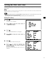
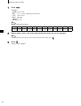
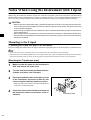
1
NON-CONTACT 3D DIGITIZER
VIVID 910/VI-910
Instruction Manual (HARDWARE)
NOTE
The VI-910 is model name for Europe and the VIVID 910 is model name for other countries.
Please note that the VIVID 910 model name is intended only for reference with this manual.
Safety Symbols
The following symbols are used in this manual to prevent accidents which may occur as result of incorrect use
of the instrument.
Denotes a sentence regarding safety warning or note.
Read the sentence carefully to ensure safe and correct use.
Denotes a prohibited operation.
The operation must never been performed.
Denotes an instruction.
The instruction must be strictly adhered to.
Denotes an instruction.
Disconnect the AC power cord from the AC outlet.
Denotes a prohibited operation.
The part must never be disassembled.
Denotes an instruction.
Connect the grounding terminal as instructed.
Denotes a sentence regarding safety precaution for laser.
Read the sentence carefully to ensure safe and correct use.
Notes on this Manual
• Copying or reproduction of all or any part of the contents of this manual without MINOLTA’s permission is strictly
prohibited.
• The contents of this manual are subject to change without prior notice.
• Every effort has been made in the preparation of this manual to ensure the accuracy of its contents. However, should
you have any questions or find any errors, please contact a Minolta-authorized service facility.
• MINOLTA will not accept any responsibility for consequences arising from the use of the instrument.
• Company names and product names which appear in this manual are their trademarks or registered trademarks.
• Contents and display examples given in this manual are subject to change.
Safety Precautions
When using this hardware, the following points must be strictly observed to ensure correct and safe use.
After you have read this manual, keep it in a safe place so that it can be referred to easily whenever it is needed.
WARNING
Failure to adhere to the following points may result
in death or serious injury.
Do not use the VIVID 910 in places where flammable or combustible gases (gasoline etc.) are
present. Doing so may cause a fire.
Do not disassemble or modify the VIVID 910.
Doing so may cause a fire or electric shock.
Always use the AC power cord supplied as a
standard accessory with the VIVID 910, and
connect it to an AC outlet (100-240 V , 5060 Hz). Failure to do so may damage the VIVID
910, causing a fire or electric shock.
Do not remove the cover as doing so may cause
electric shocks.
Do not bend, twist or pull the AC power cord excessively. In addition, do not place heavy items
on the AC power cord, or damage or modify it in
any way. Doing so may cause damage to the AC
power cord, resulting in fire or electric shock.
Take special care not to allow liquid or metal objects to enter the VIVID 910. Doing so may
cause a fire or electric shock. Should liquid or
metal objects enter the VIVID 910, turn the power OFF immediately, disconnect the AC power
cord from the AC outlet, and contact the nearest
Minolta-authorized service facility.
If the VIVID 910 will not be used for a long
time, disconnect the AC power cord from the AC
outlet. Accumulated dirt or water on the prongs
of the AC power cord’s plug may cause a fire. If
there is any dirt or water on the prongs of the AC
power cord’s plug, remove it.
The VIVID 910 should not be operated if dirt or
dust has entered through the vent holes. Doing
so may result in a fire. For periodic inspection,
contact the nearest Minolta-authorized service
facility.
When disconnecting the AC power cord’s plug,
always hold the plug and pull it to remove it.
Never pull the AC power cord itself. Doing so
may damage the AC power cord, causing a fire
or electric shock. In addition, do not insert or
disconnect the AC power cord’s plug with wet
hands. Doing so may cause electric shock.
Never stare into the laser emitting
window.
The VIVID 910 should not be operated if it is
damaged, or smoke or odd smells are detected.
Doing so may result in a fire. In such situations,
turn the power OFF immediately, disconnect the
AC power cord from the AC outlet, and contact
the nearest Minolta-authorized service facility.
Do not place a lens, mirror or optical
element in the passage of the laser
beam. Doing so may converge the laser beam, resulting in damage to your
eyes, burns or fire. To prevent the
above accidents, make sure that a wall
or similar which can block the laser
beam is located behind the object.
CAUTION
Falling to adhere to the following points may result in
injury or damage to the instrument or other property.
Be sure to connect the AC power cord’s plug to
an AC outlet that has a grounding terminal.
Make sure that the AC outlet is located near the
VIVID 910 and that the AC power cord’s plug
can be easily connected and disconnected.
Do not place the instrument on an unstable or
sloping surface. Doing so may result in its dropping or overturning, causing injury. Take care
not to drop the instrument when carrying it.
1
Laser Caution and Identification Label
Laser Caution and Identification Label
CAUTION
LASER RADIATION
DO NOT STARE INTO BEAM
LASER STRAHLUNG
NICHT IN DEN STRAHL SEHEN
MAX 30mW 690nm
CLASS 2 LASER PRODUCT
Complied with IEC Publication 60825-1:1993, Amendment-1:1997
AVOID
EXPOSURE
Laser radiation is emitted
from this aperture.
CLASS 1 LASER PRODUCT
Complies with 21 CFR Chapter 1. Subchopter J.
3-13,2-Chome, Azuchi-Machi, Chuo-ku, Osaka 541-8556 Japan
MINOLTA CO.,LTD.
manufactured
Warning Label
WARNING
2
WARNUNG
Notes On Use
• The VIVID 910 should be used within a temperature range of 10 to 40°C at a relative humidity of 65% or less.
• Do not use the VIVID 910 in direct sunlight or near sources of heat such as stoves. Doing so will cause the
temperature of the VIVID 910 to rise considerably higher than room temperature and may result in malfunctions. Use the VIVID 910 in a well ventilated area and make sure that the ventilation holes of the VIVID 910
are not blocked.
• Do not use the VIVID 910 in extremely dusty or humid areas. Doing so may result in malfunctions.
• Do not subject the VIVID 910 to strong vibration or shocks. Doing so may result in malfunctions.
• Do not disconnect cords and cables with the POWER switch of the VIVID 910 set to ON “I”. Doing so may
result in malfunctions.
• The VIVID 910 has been tested and found to comply with the limits for a Class A digital device, pursuant to
Part 15 of the FCC Rules. These limits are designed to provide reasonable protection against harmful interference when the equipment is operated in a commercial environment. This equipment generates, uses, and
can radiate radio frequency energy and, if not installed and used in accordance with the instruction manual,
may cause harmful interference to radio communications. Operation of this equipment in a residential area is
likely to cause harmful interference in which case the user will be required to correct the interference at his
own expense.
• The VIVID 910 falls into the category of a Class A information technology device based on the VCCI standards. Using it in a domestic environment may cause radio interference. In such cases, the user may be requested to take appropriate measures.
• The VIVID 910 is a class II instrument specified in IEC Publication 825. Use it according to the instructions
given in this manual.
Care On Storage
• The VIVID 910 should be stored in areas with temperatures of between –10 and +50°C. Do not store it in
areas subject to high temperature or high humidity or where sudden changes in temperature or condensation
are likely to occur. We recommend storing the VIVID 910 at a relatively constant temperature with a desiccant (silica gel etc.).
• Do not leave the VIVID 910 inside a closed car or in the trunk of a car. Under direct sunlight, the increase in
temperature can be extreme and may result in malfunctions.
• The VIVID 910 should not be stored in areas where there is an excessive amount of dust, cigarette smoke or
chemical gas. Failure to adhere to this may result in performance degradation or break-down.
• Lenses that are not in use should be capped and kept in the lens case.
Notes On Cleaning
• If the VIVID 910 needs cleaning, wipe with a soft dry cloth. Never use solvents such as thinner or benzene.
• If the lens or laser emitting window is soiled with sand or dust, blow off the dirt using a blower, and wipe
them gently with a piece of cleaning paper dampened with cleaning agent.
• In cases of malfunction, do not disassemble the VIVID 910 or attempt to repair it yourself. Contact the nearest Minolta-authorized service facility.
Notes On Maintenance
To maintain the accuracy of the high-precision Galvano mirror, that plays the most important role in measurement accuracy, a drying agent is used inside the VIVID 910. Normally, the dehumidification effect of the drying agent lasts more than one year. However, its life varies with the operating and storage environment.
To maintain the designed performance of the VIVID 910, you are recommended to replace the drying agent
once a year. Contact the nearest Minolta-authorized service facility.
3
Contents
Safety Precautions........................................................................................................................................................................
Laser Caution and Identification Label........................................................................................................................................
Warning Label..............................................................................................................................................................................
Notes On Use ...............................................................................................................................................................................
Care On Storage ...........................................................................................................................................................................
Notes On Cleaning .......................................................................................................................................................................
Notes On Maintenance.................................................................................................................................................................
1
2
2
3
3
3
3
Chapter 1 Before Using the Instrument
Package Contents (Standard Accessories) ........................................................................................................................................... 6
Optional Accessories............................................................................................................................................................................... 7
System Configuration............................................................................................................................................................................. 8
Names and Functions of Parts ............................................................................................................................................................... 9
Main Body.................................................................................................................................................................................... 9
Operation Panel.......................................................................................................................................................................... 10
Chapter 2 Preparation
Connecting the AC Power Cord..........................................................................................................................................................
Turning Power ON/OFF ......................................................................................................................................................................
Setting the Date and Time....................................................................................................................................................................
Connecting the VIVID 910 to a Computer.........................................................................................................................................
Setting the SCSI ID No..............................................................................................................................................................
Setting the Terminator ...............................................................................................................................................................
Memory Card........................................................................................................................................................................................
Notes When Using the Instrument with Tripod ................................................................................................................................
Mounting to the Tripod ..............................................................................................................................................................
12
13
15
17
18
19
21
22
22
Chapter 3 Operation
Replacing the Lens................................................................................................................................................................................
Relationship between Measurement Distance and Object.........................................................................................................
Replacing Procedure ..................................................................................................................................................................
Scanning the Object..............................................................................................................................................................................
Displaying the Scan Results.......................................................................................................................................................
High Quality Mode ....................................................................................................................................................................
Setting Focus Lock.....................................................................................................................................................................
Setting Manual Focus.................................................................................................................................................................
Adjusting the Laser Power and CCD Gain Manually................................................................................................................
Setting the Scan Reference Distance .........................................................................................................................................
Setting Auto Read ......................................................................................................................................................................
Setting the Color Level ..............................................................................................................................................................
Adjusting the White Balance .....................................................................................................................................................
Data File Management .........................................................................................................................................................................
Selecting the File Name Input Method ......................................................................................................................................
Saving a File...............................................................................................................................................................................
Loading a File ............................................................................................................................................................................
Changing a File Name................................................................................................................................................................
Deleting a File ............................................................................................................................................................................
Displaying the Status Information .....................................................................................................................................................
26
26
27
30
32
33
35
36
37
39
41
42
43
45
45
47
48
49
50
51
Chapter 4 Appendix
Error Messages .....................................................................................................................................................................................
Explanation of Measuring Principle ...................................................................................................................................................
Measuring Principle ...................................................................................................................................................................
High-Speed Image Processing Circuit .......................................................................................................................................
Time center of gravity and Space center of gravity ...................................................................................................................
Dimension Diagram ..............................................................................................................................................................................
Specifications.........................................................................................................................................................................................
4
54
56
56
57
57
58
59
Chapter 1
Before Using the Instrument
5
Package Contents (Standard Accessories)
Check that the following standard accessories are present.
6
VIVID 910 Main Body
Polygon Editing Tool
White Balance Cap VI-A10
AC Power Cord
Lens (3 types, with Lens Case)
Laser Barrier
SCSI Cable VI-A20
Half-pitch, D-sub, 50-pin male plug – 50-pin
male plug
SCSI Conversion Connector V1-A21
50-pin female plug – 50-pin male plug
Optional Accessories
When you need to purchase the following optional items, contact a Minolta-authorized service facility.
Rotary Stage Set
Tripod/Panhead
Information about the recommended tripod/
panhead, please contact the nearest Minolta
Authorized Service Facility.
Memory Card
(Compact Flash Card VI-A12 + PC Card
Adapter VI-A13)
Bench Top Frame Set
7
System Configuration
AC Power Cord
White Balance Cap
VI-A10
Polygon Editing Tool
SCSI Cable VI-A20
Memory Card
Compact Flash
Card VI-A12
+
PC Card Adapter
VI-A13
SCSI Conversion
Connector V1-A21
Computer
VIVID 910 Main Body
Laser Barrier
Tripod Base Plate
3 types of lens
(with Lens Case)
Tripod/Panhead
Rotary Stage Set
Bench Top Frame Set
Standard Accessories
Optional Accessories
(A commercially available computer can be used)
8
Names and Functions of Parts
Main Body
Handle
• The handle can be detached by removing the four screws.
• It can be attached to the bottom of
the instrument.
Light-Receiving Lens
Power Switch
AC Power Connector
Laser Emitting Window
WARNING
SCSI Port
A laser beam is emitted from this window.
Do not stare into this
window.
Viewfinder
Operation Panel
Memory Card Slot
9
Names and Functions of Parts
Operation Panel
1
2
FOCUS
AF/ MF
F
3
4
5
RELEASE
N
FOCUS LOCK
RECORD
7
SELECT
MENU
8
COLOR/ MONO
8
9
FINE/ FAST
UNDO
0
A
1 FOCUS key .........................Focuses the image manually. “F” indicates “far” and “N” indicates “near”.
2 AF/MF key ..........................Switches from auto (AF) to manual focus (MF) or vice versa.
3 FOCUS LOCK key ............Fixes the focus to scan the object.
4 RELEASE key ....................Performs a scan.
5 RECORD key .....................Records (saves) the scanned image to the Memory card.
6 SELECT key .......................Confirms selection of the items displayed on the viewfinder.
7 MENU key ..........................Displays the MENU view on the viewfinder.
8
.........................Moves from one item to another displayed on the viewfinder.
9 COLOR/MONO key ..........Switches the image on the viewfinder from color to monochrome or vice versa.
0 FINE/FAST key..................Switches scan mode from FINE to FAST or vice versa.
A UNDO key ...........................Mainly used to cancel operations of keys.
Memo
is a key provided to display the MENU view from which basic operations of this instrument can be performed. If you
are not sure during operation which view is which, press
to return to the MENU view.
(The MENU view may not be displayed even if
is pressed depending on the view currently displayed.)
10
Chapter 2
Preparation
11
Connecting the AC Power Cord
To ensure correct connection of the AC power cord, read the points given in WARNING and CAUTION carefully.
WARNING
Always use the AC power cord supplied as a standard accessory with the VIVID 910, and connect it
to an AC outlet (100-240 V , 50/60 Hz). Failure to do so may damage the VIVID 910, causing a fire
or electric shock.
Do not bend, twist or pull the AC power cord excessively. Do not place heavy items on it, scratch or
modify it. Doing so may damage it, resulting in fire or electric shock.
If you are not going to use the VIVID 910 for a long time, disconnect the AC power cord from the AC
outlet. If dirt or water accumulates on the prongs of the AC power cord’s plug, it may cause a fire. If
there is any dirt or water on the prongs, it must be removed.
When disconnecting the AC power cord’s plug, always hold the plug and pull it to remove it. Never
pull the AC power cord itself as it may be damaged, resulting in fire or electric shock. Also do not insert
or disconnect the AC power cord’s plug with wet hands. Doing so may cause electric shock.
CAUTION
Be sure to connect the AC power cord’s plug to an AC outlet that has a grounding terminal.
Make sure that the AC outlet is located near the VIVID 910 and thaVIVID 910t the AC power cord’s
plug can be easily connected and disconnected.
[Connecting Procedure]
1
Set the power switch of the VIVID 910 to OFF
(“ ”).
Note
If the AC power cord is connected to an AC outlet with the
power switch set to ON (“ ”), damage to the VIVID 910
or computer may result.
Before connecting the AC power cord, always make sure
that the power switch is set to OFF.
12
2
Plug the AC power cord to the AC power connector on the VIVID 910.
3
Plug the other end of the AC power cord to an
AC outlet.
POWER
AC IN
SCSI
Turning Power ON/OFF
[Turning Power ON]
1
Set the power switch to ON (“ ”).
Power will be supplied to the VIVID 910 and initial
setup is performed. After approximately 10 seconds,
“PLEASE OPEN LASER BARRIER AND PRESS
ANY KEY” will be displayed on the viewfinder.
POWER
AC IN
SCSI
Note
When turning power ON again after it has been turned
OFF, wait at least 5 seconds before doing so. Failure to observe this may result in malfunction or breakdown of the
VIVID 910.
2
Remove the laser barrier.
3
Press any key.
The MENU view will appear, indicating that the VIVID 910 is now ready for operation.
®SCAN
FILE LIST
CAMERA SETTINGS
CARD SETTINGS
INFO
13
Turning Power ON/OFF
[Turning Power OFF]
1
Set the power switch to OFF (“
Power will be turned OFF.
”).
POWER
AC IN
2
SCSI
Attach the laser barrier.
Note
To ensure safety, the laser barrier must be kept attached when the VIVID 910 is not in use.
14
Setting the Date and Time
Once the date and time are set, the date and time on which scan was performed will also be saved when image
data is saved.
Memo
When the VIVID 910 is used for the first time after purchase or if it has not been used for some time, the date/time data
might have been lost. If so, it must be set again.
Note
• If the date/time data has been lost, “CLOCK ERROR” will appear after power is turned ON. In this case, press any
key and proceed to step 4 to set the date and time.
• The backup battery for the date/time data is charged while the power to the instrument is ON.
[Setting Procedure]
1
Press
.
The MENU view will appear.
2
Press
to locate the arrow cursor to
“CAMERA SETTINGS”.
3
Press
.
The CAMERA SETTINGS view will appear.
4
Press
“CLOCK”.
5
Press
.
The currently set month will turn to pink.
6
Press
to select the date/time item
(month, date, year, hour, minute, second) to
be set (or changed).
The item currently displayed in pink can be set (or
changed).
to locate the arrow cursor to
SCAN
FILE LIST
®CAMERA SETTINGS
CARD SETTINGS
INFO
FEB.04.2000
®CLOCK
16:21:58
W/B
DEFAULT
SCSI ID
5
TERMINATE ENABLE
AUTO READ ON
COLOR
AUTO
HIGH QUALITY MODE OFF
FEB.04.2000
CLOCK
16:21:58
W/B
DEFAULT
SCSI ID
5
TERMINATE ENABLE
AUTO READ ON
COLOR
AUTO
HIGH QUALITY MODE OFF
15
Setting the Date and Time
7
Press
.
<Settings>
• Month: JAN to DEC
• Date: 01 to 31 (varies depending on the month)
• Year: 2000 to 2079
• Hour: 00 to 23
• Minute: 00 to 59
• Second: 00 to 59
Memo
Months are indicated as follows:
January February
JAN
8
FEB
March
April
May
June
July
MAR
APR
MAY
JUN
JUL
August September October November December
AUG
16
OCT
NOV
Repeat steps 6 and 7 until all the desired date/time items are set (or changed).
Memo
To cancel date/time setting and restore the previous date/time setting, press
9
SEP
Press
.
Setting is now complete.
.
DEC
Connecting the VIVID 910 to a Computer
To operate the VIVID 910 from a computer using the Polygon Editing Tool, the VIVID 910 must be connected
to the computer with an standard SCSI cable.
WARNING
The computer must be operated correctly and safely according to its instruction manual.
Memo
The standard SCSI cable has a 50-pin male plug (half-pitch, D-Sub) on both its ends.
Ref.
For a description of the standard accessories, refer to page 6.
[Connecting Procedure]
1
Set the power switch of both VIVID 910 and
computer to OFF (“ ”).
Note
If the AC power cord is connected to an AC outlet with the
power switch set to ON (“I”), damage to the VIVID 910 or
computer may result.
Before connecting them, always make sure that power is
turned OFF.
2
Plug the SCSI cable to a SCSI port of the VIVID
910.
3
Plug the other end of the SCSI cable to the
SCSI connector of the computer.
Connecting procedure is now complete
POWER
AC IN
SCSI
Note
Before turning ON the power to the computer, always turn
ON the power to the VIVID 910 and wait until it is ready
for operation (see page 13).
17
Connecting the VIVID 910 to a Computer
Setting the SCSI ID No.
In order for the computer to recognize that the VIVID 910 is connected to the computer via the SCSI interface,
a SCSI ID No. (0 to 6) must be set for the VIVID 910.
Memo
SCSI ID No. 5 has been set as the default setting before shipment.
Note
If other devices are connected to the computer via the SCSI interface, make sure that the SCSI ID No. of the VIVID
910 differs from those set for the devices.
[Setting Procedure]
1
Press
.
The MENU view will appear.
2
Press
to locate the arrow cursor to
“CAMERA SETTINGS”.
3
Press
.
The CAMERA SETTINGS view will appear.
4
Press
SI ID”.
5
Press
.
The currently selected SCSI ID No. will turn to pink.
6
Press
to locate the arrow cursor to “SC-
to select the desired SCSI ID No.
<Settings>
• 0 to 6: SCSI ID No.
7
18
Press
.
Setting is now complete.
SCAN
FILE LIST
®CAMERA SETTINGS
CARD SETTINGS
INFO
FEB.04.2000
CLOCK
16:21:58
W/B
DEFAULT
®SCSI ID
5
TERMINATE ENABLE
AUTO READ ON
COLOR
AUTO
HIGH QUALITY MODE OFF
FEB.04.2000
CLOCK
16:21:58
W/B
DEFAULT
SCSI ID
5
TERMINATE ENABLE
AUTO READ ON
COLOR
AUTO
HIGH QUALITY MODE OFF
Connecting the VIVID 910 to a Computer
Setting the Terminator
The VIVID 910 has a built-in SCSI terminator. The terminator is required if the VIVID 910 is the last device
of those connected in series to the SCSI interface (i.e., if only one of the SCSI ports on the VIVID 910 is used).
If the terminator is not set correctly, the VIVID 910 or devices connected to the SCSI interface may
malfunction.
Memo
“ENABLED” has been selected as the default setting before shipment.
Note
“DISABLE” must be selected if the VIVID 910 is connected via the SCSI interface but is not the last device of those
connected in series, and “ENABLE” must be selected if it is not connected via the SCSI interface. (An error message
will appear if “DISABLE” is selected even though the VIVID 910 is not connected via the SCSI interface.)
[Setting Procedure]
1
Press
.
The MENU view will appear.
2
Press
to locate the arrow cursor to
“CAMERA SETTINGS”.
3
Press
.
The CAMERA SETTINGS view will appear.
4
Press
to locate the arrow cursor to
“TERMINATE”.
5
Press
.
The currently selected option (ENABLED or DISABLED) will turn to pink.
6
Press
BLED”.
to select “ENABLED” or “DISA-
<Settings>
• ENABLED: Select this option if the terminator is to be
used.
• DISABLED: Select this option if the terminator is not to
be used.
SCAN
FILE LIST
®CAMERA SETTINGS
CARD SETTINGS
INFO
FEB.04.2000
CLOCK
16:22:28
W/B
DEFAULT
SCSI ID
5
®TERMINATE ENABLE
AUTO READ ON
COLOR
AUTO
HIGH QUALITY MODE OFF
FEB.04.2000
CLOCK
16:22:28
W/B
DEFAULT
SCSI ID
5
TERMINATE ENABLE
AUTO READ ON
COLOR
AUTO
HIGH QUALITY MODE OFF
19
Connecting the VIVID 910 to a Computer
7
20
Press
.
Setting is now complete.
Memory Card
By using the PC card adapter VI-A13, image data can be saved to the compact flash card VI-A12.
Note
• The memory card slot on the VIVID 910 can accommodate a PC card (TYPE II, PC Card Standard Release 2.1). To
save image data, insert the optional compact flash card VI-A12 into the PC card adapter VI-A13, then insert the
adapter into the slot.
• Make sure that the compact flash card and PC card adapter are positioned in the correct direction when they are
inserted. Failure to observe this may cause breakdown of the cards.
• This memory card cannot be used with the VIVID 700 (VI-700). Doing so will delete the data saved in the memory
card.
• This memory card is designed for use with the VIVID 900/910 only, so it must not be used with any other VIVID
models. Data saved by the VIVID 900 can also be retrieved by this instrument.
Ref.
For a description of data file management (saving, loading, selecting etc.), refer to pages 45 to 50.
[Inserting/Ejecting the PC Card Adapter]
1
When inserting the compact flash card into
the PC card adapter, make sure that it is correctly oriented.
Note
The PC card adapter VI-A13 with the compact flash card
VI-A12 inserted is called the memory card in this manual.
[Inserting]
1
Position the memory card so that the “ ”
mark on the memory card is aligned with “ ”
on the VIVID 910, then insert the memory card
into the slot.
Note
• Make sure that the memory card is inserted into the slot
until the eject button pops out.
• The memory card will be accessed immediately after it
has been inserted, so do not remove it for at least five seconds.
[Ejecting]
1
Press the eject button.
Note
• Never attempt to eject the memory card while scan is performed after
is pressed. Doing so may cancel scan or
hinder acquirement of correct data.
• Never attempt to eject the memory card during data loading or saving. Doing so may damage the VIVID 910 or
memory card.
21
Notes When Using the Instrument with Tripod
When using the instrument with the tripod, first attach the tripod base plate to the instrument, and then attach
the instrument to the panhead/tripod. To improve scanning accuracy, it is recommended that scanning be performed via the personal computer connected to the instrument, instead of pressing the [RELEASE] key.
CAUTION
• Make sure that the tripod base plate, panhead and tripod are secured to the instrument and each fastener on the tripod is firmly tightened. Failure to observe this point may result in the tripod overturning
or the instrument dropping.
• When placing the tripod on a floor, examine the floor conditions and flatness to make sure that the tripod is stably placed.
• After measurement is completed, the instrument must be removed from the tripod before storing them.
If the instrument is stored with the tripod attached, the tripod may overturn or the instrument may drop,
resulting in accidents.
Mounting to the Tripod
1. Mounting the Tripod base plate to the Instrument
Before mounting the instrument to the tripod, mount the tripod base plate to the instrument as explained below.
Memo
• Five screw holes for the tripod base plate are provided on both the top and base of the instrument.
• The instrument can be attached upside down to the tripod. In this case, remove the handle from the top of the instrument,
mount the tripod base plate on the top of the instrument, then mount the handle on the base of the instrument.
[Mounting the Tripod base plate]
22
1
Make sure that the power to the instrument is
OFF, and remove the power cord.
2
Turn the instrument slowly so that its side faces down, and place it on a flat table.
3
Place the tripod base plate on the base (or top)
of the instrument, and secure it with the five
screws (supplied with the tripod base plate).
* Make sure that screw washers are fitted into the dents
on the base of the instrument.
4
If you have removed the handle from the top of
the instrument, attach it to the base of the instrument.
Tripod Base Plate
Notes When Using the Instrument with Tripod
2. Mounting the Instrument to the Panhead
After you have attached the tripod base plate to the instrument, they need to be mounted to the recommended
panhead as explained below.
First, remove the accessory plate from the panhead, attach it to the instrument, then attach both to the panhead.
Memo
Three screw holes are provided on the back of the tripod base plate (the side with rubber feet), to allow mounting the tripod
base plate to the panhead.
[Attaching the Accessory Plate]
1
Remove the accessory plate from the panhead.
2
Place the top of the accessory plate on the tripod base plate (attached to the instrument),
and secure them with two screws (U3/8, supplied with the accessory plate).
U3/8 Screw
Accessory Plate
[Attaching to the Panhead]
1
Make sure that the tripod/panhead is secured in place.
2
Remove the rubber feet on the base plate with the use of a hexagonal wrench.
Memo
Remove the two rubber feet located at the rear.
Note
• If the instrument is to be removed from the tripod/panhead and located on the base plate, attach the rubber
feet.
• Store the rubber feet in a safe place after removal.
3
Slide the accessory plate (attached to the tripod base plate on the instrument) into the
panhead.
4
Tighten the slide fixing knob to firmly secure the accessory plate to the panhead.
Memo
Refer to the tripod/panhead instruction manual for details on using the accessory plate locking knob.
23
Notes When Using the Instrument with Tripod
24
Chapter 3
Operation
25
Replacing the Lens
Before starting acquisition of images, the lens may need to be replaced according to the size and distance to the
object.
Relationship between Measurement Distance and Object
With the VIVID 910, three types of lens are available: wide-angle lens, middle-angle lens and telescopic lens.
A lens suitable for the size of the object and distance must be used.
Memo
The closer the object to the VIVID 910, the higher the measurement accuracy is. On the other hand, influences of shades
produced due to roughness on the surface of the object can be reduced if the object is positioned far from the VIVID 910.
Select the most suitable lens by referring to the table given below.
WIDE Lens
Measurement Distance
Horizontal
Object Size
Vertical
600
367.0
275.2
800
486.6
364.9
1000
606.2
454.6
1200
725.8
544.4
2000
1204.2
903.2
Unit (mm)
MIDDLE Lens
Measurement Distance
Horizontal
Object Size
Vertical
600
204.7
153.6
800
270.6
203.0
1000
336.5
252.4
1200
402.4
301.8
2500
830.6
622.9
Unit (mm)
TELE Lens
Measurement Distance
Horizontal
Object Size
Vertical
600
113.9
85.4
800
151.0
113.2
1000
188.0
141.0
1200
225.1
168.8
2500
465.9
349.4
Unit (mm)
26
Replacing the Lens
Replacing Procedure
The currently installed lens can be verified by the status information.
To replace the lens with another one, follow the procedure given below.
Note
• Only the lenses supplied as standard accessories with the VIVID 910 can be used. (They are not compatible with other VIVID models since they have been calibrated with the VIVID 910 only.)
• Since the VIVID 910 is a precision instrument, do not leave it without lens when replacing the lens. Replace the lens
as soon as possible.
• If you replace the lens before saving the image data, the image data will be lost. Before replacing the lens, all the
necessary operations (e.g. saving data) must be completed.
• Do not touch the lens surface with fingers.
• If dust or dirt has collected on the lens surface, remove it using a camera air blower etc.
• Dust or dirt on the lens mount surface may produce incorrect measurement data. In this case, wipe the lens mount
surface with a clean, dry cloth and then blow it with a camera air blower etc.
• Dust and dirt collected on the lens mount surface on the body side must also be removed with a camera air blower etc.
Ref.
For display of the status information, refer to page 51.
[Replacing Procedure]
1
Remove the lens hood.
Memo
The lens hood can be fixed with its bayonet mount.
2
Turn the lens fixing ring counter-clockwise to
loose it completely.
Memo
The lens fixing ring can be fixed with its screw mount.
27
Replacing the Lens
3
Hold the external edge of the fixing ring and
pull it out.
Memo
Hold the ring with your finger located near the red mark on
the lens. This will facilitate pulling the lens.
Note
Attach the lens cap to the removed lens, place it in the lens
case and keep it in a safe place.
The following information will appear in the viewfinder as shown on the right. Check the serial number of
each lens displayed.
CHANGE LENS
TELE S/N 2001005
MIDDLE S/N 2001005
WIDE S/N 2001005
PRESS ANY KEY
4
Attach the desired lens.
• Remove the lens cap.
• Align the red mark on the lens with the one on the
lens mount socket, and insert the lens until a click is
heard.
Memo
• The position of the red mark on the lens varies with the focus point.
• Hold the ring with your finger located near the red mark
on the lens. This will facilitate inserting the lens.
5
28
Turn the lens fixing ring clockwise to secure
the lens.
Replacing the Lens
6
Attach the lens hood.
Make sure that the notch is aligned with that on the
lens, and turn the hood.
Memo
The hood must be turned until it contacts the bayonet mount
socket.
7
Press any key.
After approximately 10 seconds, “PLEASE OPEN
LASER BARRIER AND PRESS ANY KEY” will be
displayed on the viewfinder.
8
Press any key.
The MENU view will appear.
29
Scanning the Object
WARNING
Never stare into the laser emitting window.
Do not place a lens, mirror or optical element in the passage of the laser beam. Doing so may converge the laser beam, resulting in damage to your eyes, burns or fire. To prevent the above accidents, make sure that a wall or similar surface that does not reflect light is located behind the object.
Memo
For precise scan results, we recommend that you use a stable, flicker-free light source (such as a high-frequency fluorescent lamp).
[Operating Procedure]
1
Press
.
The MENU view will appear.
2
Press
“SCAN”.
3
Press
.
The color image currently captured by the VIVID 910
will appear on the viewfinder.
to locate the arrow cursor to
®SCAN
FILE LIST
CAMERA SETTINGS
CARD SETTINGS
INFO
Memo
Auto-focus will be performed automatically, and “FOCUSING” will appear. When the object is focused, “IN FOCUS”
will appear.
IN FOCUS
4
To display the object in the center of the viewfinder, change the position of the object or
move the instrument back and forth to change
the view angle.
Note
The scan subject must appear at the center of the screen to
ensure that scanning is carried out correctly. If the subject
is not centered it is possible that scanning may not execute
correctly.
30
AF FINE
Scanning the Object
5
To see the color image, press
.
A color still image captured when
will appear.
was pressed
AF FINE
AF FINE
Note
If the distance or angle to the object has been changed,
press
again to display the monochrome image to
check it.
Memo
If the captured image is too light or too dark, the color level
may need to be adjusted. You can temporarily adjust the level by pressing
or
while viewing the image.
6
Press
and select the desired scan mode.
<Settings>
• FINE: Scans with high resolution and accuracy. (2.5 seconds, 640 × 480)
• FAST: Scans at a high speed. (0.3 seconds, 320 × 240)
Memo
The resolution of color images will always be 640 × 480 regardless of the scan mode.
7
Press
.
The VIVID 910 will perform auto-focus, cause the laser beam to scan the object surface, and complete acquisition of range and color images. The scan results
(range and color images) will be displayed on the
viewfinder.
IN FOCUS
FRAME 60MB
FINE
Memo
When scanning just after the mode is switched from FINE to
FAST or vice versa, the motor will start rotation to set the
laser beam first and then focus is performed.
Ref.
< 690~ 749>
720MM
For a description of displaying the scan results, refer to page 32.
Note
• With certain objects, “AF/AE ERROR” will be displayed, indicating that auto-focus cannot be performed. In
this case, press any key to clear the error view, then set focus lock or perform manual focus.
• While scan is in progress, never insert/remove the memory card or press any keys. Doing so may cancel scan
or hinder acquisition of correct data.
Ref.
8
∙ For a description of focus lock, refer to page 35.
∙ For a description of manual focus, refer to page 36.
Check the images, and if you want to save them press
Ref.
.
For a description of saving the image in a file, refer to page 47.
Note
The acquired data will be deleted if the following operations are performed. If you need the data, it must be saved
before performing the following operations.
•
is pressed.
•
or
is pressed to return to the monitor (real-time image) view.
31
Scanning the Object
• The lens is replaced.
• The power switch is set to OFF.
9
To scan again, repeat steps 1 to 8.
Memo
If the scan results are not satisfactory, try the following:
• Adjust the laser power manually.
• Adjust the CCD gain.
• Set the scan reference distance.
• Adjust white balance.
Ref.
∙ For a description of adjusting the laser power and CCD gain, refer to page 37.
∙ For a description of setting the scan reference distance, refer to page 39.
∙ For a description of adjusting white balance, refer to page 43.
Displaying the Scan Results
When an image is captured, scan results (range image data) will be displayed on the viewfinder.
5
4
FRAME 60MB
FINE
3
720MM
6
1
2
< 690~ 749>
1 Range image
2 Effective scan range (back-forth direction) ....Displays the allowed scan range.
3 Scan mode ..........................................................Displays the scan mode (FINE or FAST).
4 File name ............................................................Displays the file name set in “AUTO [ ]” of “FILE
NAME” in the CARD SETTING view.
No file name will be displayed if “INTERACTIVE” has
been selected.
5 Remaining memory capacity............................Displays the remaining capacity of the memory card (in
MB).
6 Scan reference position.....................................Displays the distance from the front of the lens to the focus
position.
Pressing
or
image data.
32
will display the color image data on the viewfinder. Pressing it again will display the range
FINE
720MM
Scanning the Object
High Quality Mode
The instrument emits a laser beam on the object, and captures the rays reflected from the object using the CCD
for measurement.
Thus, for better measurement accuracy, it is necessary for the intensity of the reflected rays to be maintained
within the CCD’s measurement range (i.e. the range that ensures linearity).
In high quality mode, the parts of the reflected rays that are outside the CCD’s measurement range will be eliminated, so that only the data with assured linearity is output.
This provides measured data with higher accuracy than that which includes reflected rays outside the linearity
range.
Memo
If the instrument is set to High Quality Mode when you read in memory-card data that was scanned at a VIVID 910, the
instrument will automatically eliminate all data values that are outside the measurement range. This will be true even if
High Quality Mode was not turned on at the time the original data were scanned.
Note
When reading in memory-card data that was scanned at a VIVID 900, the instrument will not eliminate data values
that are outside the measurement range.
[Operating Procedure]
1
Press
.
The MENU view will appear.
2
Press
to locate the arrow cursor to
“CAMERA SETTINGS”.
3
Press
.
The CAMERA SETTINGS view will appear.
4
Press
to locate the arrow cursor to
“HIGH QUALITY MODE”.
5
Press
.
The currently selected high quality mode (ON or OFF)
will turn to pink.
6
Press
to select “ON” or “OFF”.
<Settings>
• ON: High quality mode
• OFF: Digitize mode (normal measurement mode)
SCAN
FILE LIST
®CAMERA SETTINGS
CARD SETTINGS
INFO
FEB.04.2000
CLOCK
16:21:58
W/B
DEFAULT
SCSI ID
5
TERMINATE ENABLE
AUTO READ ON
COLOR
AUTO
®HIGH QUALITY MODE OFF
FEB.04.2000
CLOCK
16:21:58
W/B
DEFAULT
SCSI ID
5
TERMINATE ENABLE
AUTO READ ON
COLOR
AUTO
HIGH QUALITY MODE OFF
33
Scanning the Object
7
Press
.
The procedure is now complete.
Memo
• If high quality mode is set to OFF (digitize mode), data outside the measurement range will be displayed in yellow on the range image.
• If high quality mode is set to ON, data outside the measurement range will be eliminated, therefore it will not be
displayed on the screen.
• If the part that you want to input is displayed in yellow or does not appear as the range image in the display at
all, press
to cancel the scan. Then adjust the laser power and gain setting and try scanning again.
34
Scanning the Object
Setting Focus Lock
With certain objects, “AF/AE ERROR” will be displayed at the end of a scan, indicating that auto-focus cannot
be performed.
In this case, press any key to clear the error view, then set focus lock as described below.
Memo
The VIVID 910 uses contrast detection type auto focus. Auto focus may not be possible with the following objects:
• White wall etc. whose contrast is low
• Objects with repetitive patterns (stripes etc.)
To scan such objects, set focus lock or perform manual focus. (Since focus lock performs active auto focus using a laser
beam, low-contrast objects can still be auto-focused.)
Ref.
For a description of manual focus, refer to page 36.
[Operating Procedure]
The following procedure applies only if an error has occurred when a scan was performed as explained on page
30.
1
Press any key to clear the error view.
2
Remove the current object and place a new
object that can be easily auto-focused in the
same position.
Memo
It is recommended that a paper with a contrasting pattern
such as a large character be affixed to the object.
3
Press
.
“FOCUS LOCK” will be displayed on the viewfinder,
and the focus will be locked when the object is focused.
AF FINE
Memo
To release focus lock, press
,
or . (The result from
pressing them will vary depending on the key pressed.)
4
Replace the object with the original one and
perform a scan.
FOCUS LOCK ON
722MM
35
Scanning the Object
Setting Manual Focus
With certain objects, “AF/AE ERROR” will be displayed at the end of a scan, indicating that auto-focus cannot
be performed.
In this case, press any key to clear the error view, then set manual focus as described below.
Memo
Auto focus may not be possible with the following objects:
• White wall etc. whose contrast is low
• Objects with repetitive patterns (stripes etc.)
To scan such objects, set focus lock or perform manual focus.
Ref.
For a description of focus lock, refer to page 35.
[Operating Procedure]
1
Measure the distance to the object with a
measuring tape.
Memo
Although the front of the lens is the reference position, this
position varies with the type of lens, so measure the distance
from the front of the VIVID 910.
2
Press
.
Manual focus mode will be active.
MF FAST
Memo
To cancel manual focus, press
3
again.
Press
and set the scan distance.
Pressing F will move the focus position far away from you.
Pressing N will move the focus position toward you.
4
36
When the scan distance is set, start scanning.
722MM
Scanning the Object
Adjusting the Laser Power and CCD Gain Manually
With certain objects, correct image data cannot be obtained.
In this case, press
at the end of scan, and adjust the laser power and CCD gain as explained below.
Memo
With the following objects, correct data may not be acquired:
• Glass etc. which transmit light
• Mirrors etc. which cause mirror reflection
• Electric bulbs etc. which themselves illuminate
• Black or blue cloth which has a low reflectance for red and similar colors
To scan these objects, the laser power or CCD gain must be adjusted manually.
[Operating Procedure]
The following procedure must be carried out if images acquired when scan was performed as explained on page
30 are unsatisfactory.
1
Press
at the end of scan.
The currently set laser power will turn to pink.
2
Press
to set the desired laser power.
FINE
<Settings>
• 0 to 255: Laser beam power
Memo
Pressing
3
will change the value in steps.
Press
.
The laser power will be set.
< 790~ 859>
®GAIN
LD 73
0
800MM
FINE
Next, the currently set CCD gain will turn to pink.
4
Press
to set the desired CCD gain.
<Settings>
• 0 to 7: CCD gain
Memo
< 790~ 859>
100
®LD
GAIN 0
800MM
The CCD gain must be adjusted only if satisfactory scan results still cannot be obtained even though the laser power
has been set to the maximum.
37
Scanning the Object
5
Press
.
The CCD gain will be set.
FINE
Next, the currently set scan reference distance will turn
to pink.
Ref.
For a description of setting the scan reference distance, refer to page 39.
6
Press
.
The monochrome image currently captured by the
VIVID 910 will be focus-locked and displayed in real
time on the viewfinder.
< 790~ 859>
.
7
38
®
FINE
Memo
A color still image can also be displayed by pressing
LD 100
GAIN 3
800MM
< 790~ 859>
Press
.
Scan will be performed with the newly set laser power and CCD gain.
LD 100
GAIN 3
800MM
Scanning the Object
Setting the Scan Reference Distance
If the entire object is not completely within the effective scan range and a part of the front or back of the object
is not scanned, press
at the end of scan, shift the reference position back or forth as described below, then
perform scan again.
[Operating Procedure]
The following procedure must be carried out if images acquired when scan was performed as explained on page
30 are unsatisfactory.
1
Perform scan and press
at the end of scan.
The currently set laser power will turn to pink.
Ref.
For a description of adjusting the laser power, refer
to page 37.
2
Press
.
The currently set CCD gain will turn to pink.
Ref.
FINE
< 790~ 859>
®GAIN
LD 73
0
800MM
FINE
For a description of adjusting the CCD gain, refer to
page 37.
3
Press
.
The currently set scan reference distance will turn to
pink.
4
Press
and set the desired scan reference distance.
If the acquired image lacks a front part of the object,
set the scan reference distance closer to you.
If the acquired image lacks a back part of the object, set
the scan reference distance away from you.
< 790~ 859>
73
®LD
GAIN 0
800MM
FINE
< 790~ 859>
LD 73
GAIN 0
777MM
®
<Settings>
• 600 to 2500: Scan reference distance (Unit: mm)
Memo
Pressing
will change the value in steps.
39
Scanning the Object
5
Press
.
The monochrome image currently captured by the
VIVID 910 will be focus-locked and displayed in real
time on the viewfinder.
MF FAST
Memo
A color still image can also be displayed by pressing
.
6
< 790~ 859>
Press
.
Scan will be performed with the newly set scan reference position.
Memo
If the acquired image still lacks a front or back part of the object, try the following:
• If you are using the TELE or MIDDLE lens, replace it with the WIDE lens and perform scan.
• Increase the distance from the VIVID 910 to the object and perform scan.
• Perform scan from different angles to acquire multiple images.
• Perform scan in FINE mode.
40
LD 73
GAIN 0
777MM
Scanning the Object
Setting Auto Read
With certain objects, a better image can sometimes be acquired if the condition of the laser beam emitted to
scan a range image differs from that emitted to scan a color image.
In this case, set Auto Read to OFF as explained below.
[Operating Procedure]
1
Press
.
The MENU view will appear.
2
Press
to locate the arrow cursor to
“CAMERA SETTINGS”.
3
Press
.
The CAMERA SETTINGS view will appear.
4
Press
to locate the arrow cursor to “AUTO READ”.
5
Press
.
The currently set auto read mode (ON or OFF) will
turn to pink.
6
Press
7
Press
.
Auto Read mode will be set to OFF.
to select “OFF”.
SCAN
FILE LIST
®CAMERA SETTINGS
CARD SETTINGS
INFO
FEB.04.2000
CLOCK
16:21:58
W/B
DEFAULT
SCSI ID
5
TERMINATE ENABLE
®AUTO READ ON
COLOR
AUTO
HIGH QUALITY MODE OFF
FEB.04.2000
CLOCK
16:21:58
W/B
DEFAULT
SCSI ID
5
TERMINATE ENABLE
AUTO READ ON
COLOR
AUTO
HIGH QUALITY MODE OFF
Memo
If Auto Read is set to OFF, no color image will be scanned even though
image, press
again.
is pressed to scan. To scan a color
41
Scanning the Object
Setting the Color Level
The exposure level (brightness/darkness) used for scanning color images can be set.
[Operating Procedure]
1
Press
.
The MENU view will appear.
2
Press
to locate the arrow cursor to
“CAMERA SETTINGS”.
3
Press
.
The CAMERA SETTINGS view will appear.
4
Press
“COLOR”.
5
Press
.
The currently set color level will turn to pink.
6
Press
to locate the arrow cursor to
to set the desired laser power.
<Settings>
• AUTO: Scans a color image with the same exposure level
as the one for monochrome images.
• 0 to 9: The larger the value, the brighter the image.
7
SCAN
FILE LIST
®CAMERA SETTINGS
CARD SETTINGS
INFO
FEB.04.2000
CLOCK
16:21:58
W/B
DEFAULT
SCSI ID
5
TERMINATE ENABLE
AUTO READ ON
®COLOR
AUTO
HIGH QUALITY MODE OFF
FEB.04.2000
CLOCK
16:21:58
W/B
DEFAULT
SCSI ID
5
TERMINATE ENABLE
AUTO READ ON
COLOR
AUTO
HIGH QUALITY MODE OFF
Press
.
The new color level will be set.
Memo
While checking the color image by pressing
porarily by pressing
.
42
before starting scan, it is possible to change the color level tem-
Scanning the Object
Adjusting the White Balance
The color of an object varies slightly depending on the type of light source. To acquire accurate color image
data, adjust the white balance as described below under the light source to be used.
When scanning, we recommend that you use a stable, flicker-free light source (such as a high-frequency fluorescent lamp).
Memo
The white balance has been adjusted under fluorescent light before shipment.
[Operating Procedure]
1
Set the light source so that the lighting condition is the same as that under which scan
is to be performed.
2
Attach the white balance cap to the VIVID 910
as illustrated.
3
Press
.
The MENU view will appear.
4
Press
to locate the arrow cursor to
“CAMERA SETTINGS”.
5
Press
.
The CAMERA SETTINGS view will appear.
6
Press
B”.
to locate the arrow cursor to “W/
SCAN
FILE LIST
®CAMERA SETTINGS
CARD SETTINGS
INFO
FEB.04.2000
CLOCK
17:09:19
®W/B
DEFAULT
SCSI ID
5
TERMINATE ENABLE
AUTO READ ON
COLOR
AUTO
HIGH QUALITY MODE OFF
43
Scanning the Object
7
Press
8
Press
9
Press
.
“CALIBRATING” will be displayed and white balance will be adjusted.
.
to select “CALIBRATE”.
FEB.04.2000
CLOCK
17:09:19
W/B
CALIBRATE
SCSI ID
5
TERMINATE ENABLE
AUTO READ ON
COLOR
AUTO
HIGH QUALITY MODE OFF
Memo
If “DEFAULT” is selected and
light) will be restored.
44
is pressed at step 6, the default white balance (i.e. calibrated under fluorescent
Data File Management
The acquired image data can be saved in an optional memory card. Once the data is saved, it can be loaded to
the VIVID 910 or to a computer using the Polygon Editing Tool.
Memo
Insert the compact flash card into the PC card adapter, then insert them into the memory card slot on the VIVID 910.
Note
The memory card (compact flash card VI-A12 + PC card adapter VI-A13) supplied with the VIVID 910 must be used.
Ref.
For a description of the memory card, refer to page 21.
Selecting the File Name Input Method
Two methods are available for assigning a file name to image data when saving it: “AUTO” to assign file names
automatically, and “INTERACTIVE” to assign them interactively.
[Operating Procedure]
1
Press .
The MENU view will appear.
2
Press
to locate the arrow cursor to
“CARD SETTINGS”.
3
Press
.
The currently selected method will be displayed.
<Settings>
• AUTO <FRAME>:
Automatically adds a serial number (001 to 999) to the
prefix file name (up to five characters) specified in “< >”
and saves the data.
• INTERACTIVE:
Asks you to enter a file name each time you attempt to
save the data. (A view asking you to enter a file name will
appear each time you attempt to save the data.)
SCAN
FILE LIST
CAMERA SETTINGS
®CARD SETTINGS
INFO
FILENAME FORMAT
®AUTO<FRAME>
45
Data File Management
4
Press
.
The currently selected method will turn to pink.
5
Press
6
Press
.
The selected method will be set.
to select the desired method.
FILENAME FORMAT
AUTO<FRAME>
If “INTERACTIVE” is selected, selection of file name input method is now complete.
If “AUTO” is selected, proceed to step 7.
7
If “AUTO” is selected, select the character to
be changed from the prefix file name displayed in < > by pressing
.
Memo
FILENAME FORMAT
AUTO<FRA
>
Moving through the prefix file name from one character to
another by pressing , the character located right on
will be cleared.
8
Press
ter.
to select the desired new charac-
Memo
Characters can be selected from alphabets (A to Z) and numbers (0 to 9).
9
Repeat steps 7 and 8 to complete the new prefix file name (up to five characters).
Press
.
10 The
specified file name will be set.
46
Data File Management
Saving a File
The acquired data can be saved in a file to the memory card as described below.
[Operating Procedure]
1
Performs a scan.
Ref.
2
Press
For a description of scan, refer to page 30.
.
Note
If you have checked the color image data after scanning,
press
to switch to the range image view before this
step. The RECORD key is not effective while the color image is displayed.
The procedure varies with the file name input method.
Ref.
For a description of file name input method, refer to page 45.
If “AUTO” file name input method has been selected, “RECORDING” will be displayed and the data
will be saved.
If “INTERACTIVE” file name input method has been selected, proceed to step 3.
3
If “INTERACTIVE” file name input method has
been selected, press
to specify the desired file name.
Memo
Characters can be selected from alphabets (A to Z) and numbers (0 to 9).
FINE
ABCDEFGH.CDM
4
Press
720MM
to select the character to be changed.
Memo
Moving through the prefix file name from one character to another by pressing
will be cleared.
, the character located right on
5
Repeat steps 3 and 4 to complete the file name (up to eight characters).
6
Press
.
“RECORDING” will be displayed and the data will be saved under the specified file name.
47
Data File Management
Loading a File
Data saved in the memory card can be loaded as described below.
[Operating Procedure]
1
Press
.
The MENU view will appear.
2
Press
to locate the arrow cursor to
“FILE LIST”.
3
Press
.
The FILE LIST view will appear.
Note
The data obtained by step shot scan using the Polygon Editing Tool Software (the instrument is connected to a personal computer) will not be displayed.
SCAN
®FILE LIST
CAMERA SETTINGS
CARD SETTINGS
INFO
FILE LIST
®FRAME001.CDM
FRAME002.CDM
FRAME003.CDM
FRAME004.CDM
FRAME005.CDM
FRAME006.CDM
FRAME007.CDM
FRAME008.CDM
FRAME009.CDM
FRAME010.CDM
FRAME011.CDM
FRAME012.CDM
NEXT
4
Press
5
Press
to check the information regarding the selected file.
“LOADING” will be displayed, and the following views will appear.
to select the file you want to load.
Memo
• Each time
is pressed, the view will switch as follows. Even if a view is currently displayed, you can still
display file information of other files listed in the FILE LIST view by pressing
.
ATTRIBUTES
FILENAME
FRAME035.PM
DATE
FEB.04.2000
TIME
17:07:31
MODE
FINE
LENS
WIDE
FOCALLENGTH
8MM
DISTANCE
746MM
MODEL NAME
910
Scan Information view
FILE LIST
®FRAME001.CDM
FRAME002.CDM
FRAME003.CDM
FRAME004.CDM
FRAME005.CDM
FRAME006.CDM
FRAME007.CDM
FRAME008.CDM
FRAME009.CDM
FRAME010.CDM
FRAME011.CDM
FRAME012.CDM
NEXT
File List view
Color Image view
Range Image view
• The following information can be checked in the Scan Information view.
File name
Saved time
Scan lens
Saved date
Scan mode
Focal length
Scan distance
Machine that took the scan
48
ATTRIBUTES
FILENAME
FRAME035.PM
DATE
FEB.04.2000
TIME
17:07:31
MODE
FINE
LENS
WIDE
FOCAL LENGTH
8MM
DISTANCE
746MM
MODEL NAME
910
Data File Management
Changing a File Name
File names of the data stored in the memory card can be changed.
[Operating Procedure]
1
Select the data whose file name is to be changed.
Ref.
For a description of selecting a file, refer to page 48.
2
Press
.
A file edit view will appear.
3
Press
to locate the arrow cursor to
“CHANGE FILENAME”.
4
Press
.
The last character of the selected file name will turn to
pink.
SELECTED FILE
FRAME020.CDM
®CHANGE FILENAME
DELETE FILE
SELECTED FILE
5
Press
changed.
to select the character to be
Memo
Moving through the prefix file name from one character to
another by pressing , the character located right on
will be cleared.
6
Press
FRAME020.CDM
®CHANGE FILENAME
DELETE FILE
>FRAME020
to select the desired new character.
Memo
Characters can be selected from alphabets (A to Z) and numbers (0 to 9).
7
Repeat steps 5 and 6 to complete the desired file name.
Memo
To cancel changing the file name and restore the original file name, press
8
.
Press
.
The file name will be changed.
The view shown at step 1 will reappear.
49
Data File Management
Deleting a File
Files stored in the memory card can be deleted.
[Operating Procedure]
1
Select the file you want to delete.
Ref.
For a description of selecting a file, refer to page 48.
2
Press
.
A file edit view will appear.
3
Press
to locate the arrow cursor to “DELETE FILE”.
4
Press
.
The selected file name will turn to pink, and “CONFIRM TO DELETE?” will be displayed.
Once a file is deleted, it cannot be restored any more. Thus,
before deleting it, double-check its file name etc.
5
.
Press
.
The file will be deleted.
The FILE LIST view will reappear.
50
FRAME020.CDM
CHANGE FILENAME
®DELETE FILE
SELECTED FILE
Note
If you do not want to delete, press
SELECTED FILE
FRAME020.CDM
CHANGE FILENAME
®DELETE FILE
>CONFIRM TO DELETE?
Displaying the Status Information
The model name, version, lens information, total capacity and unoccupied capacity of the memory card can be
displayed.
[Operating Procedure]
1
Press
.
The MENU view will appear.
2
Press
FO”.
3
Press
.
The status information will be displayed as shown below.
CAMERA
LENS
PC CARD
to locate the arrow cursor to “IN-
• MODEL NAME: Model name (VIVID 910)
• VERSION: Version No.
• S/N: Serial No.
•
•
•
•
TELE S/N: TELE lens’s serial No.
MIDDLE S/N: MIDDLE lens’s serial No.
WIDE S/N: WIDE lens’s serial No.
*: Indicates the currently installed lens.
SCAN
FILE LIST
CAMERA SETTINGS
CARD SETTINGS
®INFO
CAMERA MODEL NAME 910
VERSION
1.00
S/N
2001005
LENS
TELE S/N 2001005
MIDDLE S/N 2001005
WIDE S/N 2001005
MEMORY CARD
TOTAL SPACE 122MB
FREE SPACE 60MB
• TOTAL SPACE: Total capacity of memory card
• FREE SPACE: Unoccupied capacity of memory card
51
Displaying the Status Information
52
Chapter 4
Appendix
53
Error Messages
The following error messages appear if incorrect operation is performed or an abnormality occurs with the
VIVID 910. If an error message appears, take the appropriate corrective actions as shown in the table below.
If the problem still does not disappear, contact a Minolta-authorized service facility.
Error Message
(Alphabetically)
AF/AE ERROR
LASER BARRIER
MAY BE CLOSED
PRESS ANY KEY
AF ERROR
LOW CONTRAST
PRESS ANY KEY
BACKUP ERROR
PRESS ANY KEY
CAUTION
LASER SCANNER IS
OUT OF ORDER
PLEASE TURN OFF
CHANGE LENS
TELE S/N ********
MIDDLE S/N ********
WIDE S/N ********
PRESS ANY KEY
CLOCK ERROR
PRESS ANY KEY
DIRECTORY FULL
PLEASE INSERT
ANOTHER MEMORY CARD
OR
PRESS ANY KEY
ERROR
OUT OF DISTANCE RANGE
PRESS ANY KEY
INVALID FORMAT
PLEASE INSERT
ANOTHER MEMORY CARD
OR
PRESS ANY KEY
LIGHT IMPROPER
NO FREE SPACE
PLEASE INSERT
ANOTHER MEMORY CARD
OR
PRESS ANY KEY
NO MEMORY CARD
PLEASE INSERT
A CARD
OR
PRESS ANY KEY
54
Meaning
Auto-focus or auto-exposure failed.
Press any key.
Auto-focus failed due to low contrast
of the object. Press any key.
Failed to back up the data.
Press any key.
The laser beam is not emitted properly. Turn off the power immediately.
Action
Remove the laser cap.
In the case of an object for which it is difficult to acquire correct images, set the
focus lock or manual focus.
In the case of an object for which it is difficult to acquire correct images, set the
focus lock or manual focus.
All the settings will be initialized, so set
them again.
Highly dangerous! Turn off the power
immediately and contact a Minoltaauthorized service facility.
The lens is now being replaced.
Press any key.
Attach the lens hood properly.
Check the serial No. of the lens, and
replace the lens properly.
The clock is abnormal.
Press any key.
The maximum allowed number of
files has already been stored. Replace
the compact flash card with a new
one, or press any key.
The date/time data will be initialized, so
set it again.
Insert a memory card that has sufficient
unoccupied memory capacity.
Delete files from the currently inserted
memory card.
The object is not located within the
specified object distance range. Press
any key.
The memory card has not been initialized.
Press any key.
Place the object in a position 0.5 m to 2.5
m away from the VIVID 910.
Insufficient amount of light
There is insufficient unoccupied
capacity on the memory card.
Press any key.
Illuminate the object brighter and scan it.
Insert a memory card that has sufficient
unoccupied memory capacity.
Delete files from the currently inserted
memory card.
No memory card is inserted.
Insert another memory card or press
any key.
Insert a memory card into the slot.
Insert an initialized memory card into the
slot or initialize the current memory card.
(It is not possible to initialize a memory
card using the VIVID 910.)
Error Messages
Error Message
(Alphabetically)
MEMORY CARD IS
EJECTED
PRESS ANY KEY
MEMORY CARD IS
EJECTED
RECORDING IS CANCELED
PRESS ANY KEY
SAME FILE NAME
SYSTEM ERROR
PLEASE TURN OFF
TERMINATE ERROR
PRESS ANY KEY
SET TERMINATE ENABLE
UNKNOWN MEMORY
CARD
PLEASE INSERT
ANOTHER MEMORY CARD
OR
PRESS ANY KEY
WB ERROR
LIGHT IMPROPER
PRESS ANY KEY
Meaning
Action
The memory card has been ejected.
Press any key.
Insert a memory card into the slot.
The memory card has been ejected.
Press any key.
Insert a memory card into the slot.
A file of the same file name already
exists.
A system error has occurred.
Turn OFF the power.
Specify another file name.
SCSI terminator error has occurred.
Press any key and set the terminator
to “ENABLE”.
The currently inserted memory card
is not suitable for the VIVID 910.
Insert another memory card or press
any key.
Failed to adjust white balance.
Press any key.
Turn OFF the power, then turn it ON
again. If the problem still does not disappear, contact a Minolta-authorized service
facility.
Set the terminator to “ENABLE”.
Insert a suitable memory card into the
slot.
Adjust white balance in a bright place.
(White balance in effect before occurrence of this error has not been updated.)
55
Explanation of Measuring Principle
Measuring Principle
The VIVID 910 uses the light-stripe method to emit a horizontal stripe light through a cylindrical lens to the
object. The reflected light from the object is received by the CCD, and then converted by triangulation into distance information.
This process is repeated by scanning the stripe light vertically on the object surface using a Galvano mirror, to
obtain a 3D image data of the object.
In addition, a color image of the object is also obtained by scanning the CCD through a RGB filter while the
stripe light is not emitted. (A band pass filter is used when stripe light is emitted.)
Galvano mirror
Object
Receiving lens
Exchange
type
Emitting lens
Filter set (R, G, B, BP)/rotary type
Laser beam
56
Explanation of Measuring Principle
High-Speed Image Processing Circuit
The stripe light is scanned on the CCD image plane at two horizontal lines per frame (FAST mode) or one horizontal line per frame (FINE mode), and the CCD is driven so that the block readout start position is shifted
two lines per frame (FAST mode) or one line per frame (FINE mode).
Approximately 270 frames of the imager are acquired in FAST mode, whilst approximately 600 frames are acquired in FINE mode.
∙ CCD drive rate: 12.5MHz
∙ Block readout: 36 lines (FAST mode)/125 lines (FINE mode)
∙ Data acquisition speed: 0.3 sec. (FAST mode)/2.5 sec. (FINE mode)
The output signal from the CCD is then converted into a digital signal, which is then subjected to digital signal
processing. The signal processed data is finally saved in the frame memory.
Frame
Memory
Frame interline
Transfer CCD
A/D
FIFO
DSP
Clock Generator
Host I/F
Galvano
Scanner
Laser
Diode
CPU
Driver
CPU Data Bus
Time center of gravity and Space center of gravity
Time center of gravity is the center of gravity of the variation in the LD light passing CCD’s one picture element over a period of time.
Space center of gravity is the center of gravity of the spatial variation in the LD light on the CCD at a certain
time.
With this instrument, 3D images are obtained by calculating the Time center of gravity of each picture element
of CCD. Intersection of the viewing angle of each picture element of the CCD and passing angle (time) of the
stripe light is calculated.
Compared to the Space center of gravity, use of Time center of gravity can reduce influences of sensitivity variation of CCD’s picture elements and variation of brightness of the object.
57
Dimension Diagram
(Unit: mm)
58
Specifications
Model Name
Measurement Method
AF
Light-Receiving lens
(exchangeable)
Object Distance Range
Field of View
Laser Power
Laser Scanning Method
Scan Mode
X Direction Input Range
(Varies with the distance)
Y Direction Input Range
(Varies with the distance)
Z Direction Input Range
(Varies with the distance)
Accuracy
Precision (Z, σ, Typ.)
Input Time
Image Data Transfer Time to
Computer
Allowed Environmental
Light
Imaging Device
Output Data Points
Output Format
Memory Media
Data Capacity
Viewfinder
Output Interface
Power
Non-contact 3D digitizer VIVID 910/VI-910
Triangulation, light-stripe method
Image surface AF (contrast method), Active AF
TELE
: Focal distance f=25 mm
MIDDLE: Focal distance f=14 mm
WIDE : Focal distance f=8 mm
0.6 to 2.5 m (2 m for WIDE lens)
0.6 to 1.2 m
Max. 30 mW, 690 nm
*IEC Class 2 (for Europe) with IEC PUBLICATION 60825-1:1993, Amendment-1:1997
*FDA Class I (for US.) with 21CFR chapter 1, Subchapter J.
Galvano mirror
FAST (high-speed mode)/FINE (high-accuracy mode)
High quality mode
Dynamic range mode
(Selectable when measurement is taken using the Polygon Editing Tool Software
(standard accessory))
111 to 463 mm (TELE), 198 to 823 mm (MIDDLE),
359 to 1196 mm (WIDE)
83 to 347 mm (TELE), 148 to 618 mm (MIDDLE),
269 to 897 mm (WIDE)
40 to 500 mm (TELE), 70 to 800 mm (MIDDLE),
110 to 750 mm (WIDE/FINE mode)
TELE
X: ±0.22 mm, Y: ±0.16 mm,
Z: ±0.10 mm to the Z reference plane
MIDDLE X: ±0.38 mm, Y: ±0.31 mm,
Z: ±0.20 mm to the Z reference plane
WIDE
X: ±1.40 mm, Y: ±1.04 mm,
Z: ±0.40 mm to the Z reference plane
(Conditions: FINE mode, distance 0.6 m, Minolta’s standard 3D chart, Minolta’s
processing software, temperature 20ºC, relative humidity 65% or less)
TELE 8 µm, MIDDLE 16 µm, WIDE 32 µm
(Conditions: FINE mode, distance 0.6m, Minolta’s standard 2D chart, Minolta’s
processing software, temperature 20°C, relative humidity 65% or less)
0.3 sec. (FAST mode), 2.5 sec. (FINE mode),
0.5 sec. (COLOR)
Approx. 1 sec. (FAST mode), 1.5 sec. (FINE mode)
500 lx or less
3D data
: 1/3-inch frame transfer CCD (340,000 picture elements)
Color data : 3D data is shared (color separation by rotary filter)
3D data
: 640 × 480 (FINE mode)
320 × 240 (FAST mode)
Color data : 640 × 480
3D data
: Original format
(Converted to 3D by the standard utility software)
Color data : RGB 24-bit raster scan data
ATA PC card Type II
1.6MB/card (FAST mode), 3.6MB/card (FINE mode) (in total of 3D data and color
data)
5.7-inch LCD (320 × 240 picture elements)
SCSI II (DMA synchronous transfer)
100 to 240V (50/60Hz),
0.6A (at 100V )
59
Specifications
Model Name
Dimensions
Mass
Operating environment
Storage Temperature Range
Non-contact 3D digitizer VIVID 910/VI-910
213 (W) × 413 (H) × 271 (D) mm
Approx. 11 kg
Operating Temperature Range: 10 to 40°C; 65% RH or less/no condensation; Installation category: II; Pollution degree: 2; Maximum altitude: 2000 m
-10 to 50°C, 85% or less (at 35°C)/no condensation
The above specifications are subject to change without prior notice.
60
Minolta Co.,Ltd.
9222-1888-19
3-13, 2-Chome, Azuchi-Machi, Chuo-Ku, Osaka 541-8556, Japan
© 2001 Minolta Co., Ltd.
ACHARR(1) Printed in Japan