1
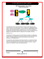
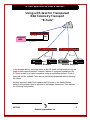
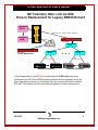
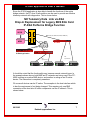
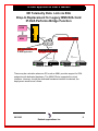
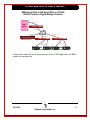
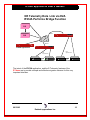
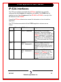
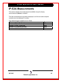
IP-E2A E2A Telemetry Interface Application User’s Manual Build #4 721 Route 202-206 Bridgewater, NJ 08807 fax: 908.218.1736 phone: 908.218.0500 email: [email protected] http://www.datatekcorp.com IP-E2A Application User's Manual CONTENTS INTRODUCTION ........................................................................................................................................ 3 IP-E2A FEATURES................................................................................................................................... 11 SUGGESTED REFERENCE .................................................................................................................... 12 IP-E2A INTERFACES .............................................................................................................................. 13 IP-E2A COMMAND SET.......................................................................................................................... 15 IP-E2A MEASUREMENTS ...................................................................................................................... 20 WARRANTY .............................................................................................................................................. 21 END-USER LICENSE AGREEMENT FOR SOFTWARE ................................................................... 22 06/19/03 2 Datatek Applications Inc. Introduction The E-Telemetry systems, with its associated central and remote equipment, was introduced originally for the purpose of centralizing alarm collection, effecting remote controls, elimination of staff from rural buildings, and utilizing the remaining maintenance staff in a more effective manner. As technology advanced, E-Telemetry was used, with several central units, and a multitude of remote units. The E-telemetry units were for surveillance and control applications in the areas of switching, distribution, and interoffice facility management. The central units were originally manual and not capable of managing numerous remote units. The later central units became rather large minicomputer based operations systems. The remote units also evolved from a collection of discrete components to microprocessor based units. There are two basic functions of the remote units. The first is to monitor the binary states of alarm points supplied as relay contacts, and transmit these monitored states back to the operations systems on demand. The second is to provide relay closures to the monitored equipment under the control of the operations system. The E-Telemetry protocol is used to join the central operations systems and remote units. The following is a typical diagram of the E-Telemetry system as it is deployed: IP-E2A Application User's Manual NE Telemetry Data Link via E2A Typical Deployment DK/BNS DK/BNS SCCS NFM CS A M P M C P M SAM BNS WAN T R K T R K E2A Bridge Bridge Bridge E2A Asynchronous E2A Asynchronous Network Elements Network Elements The operations system communicates with a central access point for a set of network element on a bridge network. This is a serial port an a BNS/Datakit E2A card, or it may be a direct interface on the host if there is no BNS/Datakit network present. The central access point is attached to one or more tiers of bridges to broadcast the message to multiple network elements. In some installations, these bridges are actually 202T data sets configured as a half duplex multi-drop distribution net. The distribution scheme works well for the E-telemetry interface, but diagnosing problems can be exceptionally time consuming with a multi-leg multi-drop bridge network. This paper attempts to address those problems by the eventual elimination of the bridge network. One approach to the elimination of the bridge network is to centralize the bridge functions, and distribute individual tail circuits to each remote device. Of course, if this were done physically; the cost would be prohibitive. However, it makes sense to do it logically. Consider the following solution: 06/19/03 4 Datatek Applications Inc. IP-E2A Application User's Manual Using a DT-4xxx for Transparent E2A Telemetry Transport “E-Tails” IP DT-4xxx NMA E2A Asynchronous DT-4xxx E2A Asynchronous Network Elements DT-4xxx E2A Asynchronous Network Elements In the diagram above, the bridge exists at the OS head. Individual tail circuits are used to each network element. However, instead of a physical connection; the DT-4xxx is used for a logical connection using an embedded network. Each of these tail circuits (called E-Tails) can be individually diagnosed without affecting the others. Another approach would be to replace the E2A ports on the Datakit feeder network and provide a drop-in solution to the bridges themselves. This requires the following configuration. 06/19/03 5 Datatek Applications Inc. IP-E2A Application User's Manual NE Telemetry Data Link via E2A Drop-In Replacement for Legacy BNS E2A Card DK/BNS SCCS NFM CS A P M C P M M U T M U M I BNS Trunk (IP, ATM, FR, HDLC, TDM, etc) 10BaseT IP DT-4000 Bridge 10BaseT DT-6xxx IP-E2A Application Bridge E2A Asynchronous Network Elements Bridge E2A Asynchronous Network Elements In the diagram above, the DT-6xxx is executing the IP-E2A application that interfaces to the SCCS and NFM operations system without changes. As far as these operations systems are concerned, they are communicating via a Datakit E2A port. This allows a smooth and effective migration of these components. 06/19/03 6 Datatek Applications Inc. IP-E2A Application User's Manual Since the IP-E2A application is also able to handle the functions of the entire bridge network, the DT-4xxx E-tails solution can be used to provide an effective telemetry network with diagnostics. This is shown below: NE Telemetry Data Link via E2A Drop-In Replacement for Legacy BNS E2A Card IP-E2A Performs Bridge Function DK/BNS SCCS NFM CS A M P M C P M U T M BNS Trunk (IP, ATM, FR, HDLC, TDM, etc) U M I 10BaseT DT-4000 IP 10BaseT 10BaseT DT-6xxx IP-E2A Application DT-4xxx E2A Asynchronous Network Elements E2A Asynchronous Network Elements It should be noted that the functionality may traverse several network types. In the example shown above, both BNS and IP networks are being used. One DT4000 is acting as a native BNS device, and another is acting as an IP native device. The interaction is completely seamless. Of course all devices can be IP native. The exception is the host interface which is has the requirement of not being changed. This requires only one BNS connection at the host site. All other components use the IP network. This is shown below: 06/19/03 7 Datatek Applications Inc. IP-E2A Application User's Manual NE Telemetry Data Link via E2A Drop-In Replacement for Legacy BNS E2A Card IP-E2A Performs Bridge Function DK/BNS SCCS NFM CS A M P M C P M U M I 10BaseT 10BaseT IP DT-4xxx 10BaseT 10BaseT DT-6xxx IP-E2A Application DT-4xxx E2A Asynchronous Network Elements E2A Asynchronous Network Elements There may be a situation where an OS, such as NMA, provides support for E2A endpoints with dedicated hardware. The NMA OS also supports the virtual interface. However, should the dedicated hardware interface be desired, the deployment would be as follows: 06/19/03 8 Datatek Applications Inc. IP-E2A Application User's Manual NMA Serial E2A to NE Serial E2A via IP-E2A IP-E2A Performs Digital Bridge Function E2A Asynchronous NMA w/ETEL DT-4xxx 10/100 BaseT IP 10/100 BaseT 10/100 BaseT 10/100 BaseT DT-6xxx IP-E2A Application DT-4xxx DT-4xxx E2A Asynchronous E2A Asynchronous Network Elements Network Elements Finally, some hosts will use a native interface to the IP-E2A application. No BNS network is required at all. 06/19/03 9 Datatek Applications Inc. IP-E2A Application User's Manual NE Telemetry Data Link via E2A IP-E2A Performs Bridge Function OS 10BaseT OS IP DT-4000 10BaseT 10BaseT DT-6061 IP-E2A Application DT-4000 E2A Asynchronous Network Elements E2A Asynchronous Network Elements The intent of the IP-E2A application, and the E-Telemetry features of the DT-4xxx are to provide a simple and effective migration scheme for this very important interface. 06/19/03 10 Datatek Applications Inc. IP-E2A Application User's Manual IP-E2A Features This section defines the features of the IP-E2A application. This is done as a list, but some features require further elaboration. • • • • • • • • Support for one Host E2A interface per instance. The E2A interface is typically originating on a Datakit CPM module, and a virtual port on a UMI is used to connect the host to the DT-6xxx IP-E2A instance. Up to 64 bridge E-tails per instance of the IP-E2A application. Support for the BNS E2A port protocol. This eliminates any host software changes. Automatic configuration of the DT-4xxx ports set up for E-Tails. Up to 30 instances of the IP-E2A application may be present on the same DT-6160, or DT-6061. Up to 48 instances of the IP-E2A application may be present on the same DT-6260. 1 Configuration Console is available to be used by the IP-E2A administrator for configuration, diagnostic and measurement purposes. The IP-E2A application requires no configuration for proper operation. 06/19/03 11 Datatek Applications Inc. IP-E2A Application User's Manual Suggested Reference The following documents are resident at http://www.datatekcorp.com under the documentation button. Document DT-6xxx Platform User’s Manual. DT-4000 User’s Manual. DT-42xx User’s Manual. DT-6xxx Redundant Operation White Paper. Scope Describes the DT-6xxx Embedded Network Processor infrastructure and command set. This includes configuration information, hardware specifications, and SNMP MIB support. The DT-6xxx is the infrastructure on which the IP-E2A application shall reside. Describes the DT-4xxx multi-protocol access device. The DT-4xxx is used as the interface for physical serial connections to the E-Telemetry devices. Describes the method of operating the DT-6xxx in a 1+1 sparing configuration. Note: This paper is not posted on the above site. Contact the author for a copy via email. 06/19/03 12 Datatek Applications Inc. IP-E2A Application User's Manual IP-E2A Interfaces The TCP port numbers associated with a DT-6xxx application are normally referenced by which instance the application is installed. The IP-E2A may be installed on any of the 30 instances of the DT-6061 or DT-6160, or on any of the 48 instances of the DT-6260. Consult the DT-6xxx infrastructure manual for information on how to install an application. The TCP Numbers associated with the IP-E2A application instance are as follows: Set #Channels TCP Port# Usage OA&M 1 10000 + Instance# Host 1 30000 + (200 * Instance#-1) E-Tails 64 30000 + (200 * Instance#-1) + 1. Administration of the IP-E2A application. This is the standard configuration TCP port number for a DT-6xxx application. For example, instance #1 is 10001, instance #2 is 10002, and so on. Connections to this TCP port are made via a Telnet client. There is a single connection to the Operations System host. For instance #1, this is 30000, for #2 it is 30200, through instance #30 at 35800. There are up to 64 E-tail connections. Each E-tail may be connected to a DT-4xxx port. The DT-4xxx port is automatically initialized at connection. All 64 Etails are considered a single bridge network. 06/19/03 13 Datatek Applications Inc. IP-E2A Application User's Manual Serial Host 1 30000 + (200 * Instance#-1) + 2. There is a single serial host connection per instance. The serial host connection is mutually exclusive with the OS host connection on the same instance. The Serial Host is expected to be connected to a DT-4xxx device that is serially attached to the host E2A port. 06/19/03 14 Datatek Applications Inc. IP-E2A Application User's Manual IP-E2A Command Set Input Conventions All parameters may be given on the command line. Parameters of the form name=<value> may be given in any order. Commands may be entered in upper or lower case. Parameters of the form name=value may use upper or lower case for name. Default values, if any, are shown in parenthesis as part of the prompt. Case is preserved for values. Backspace erases one character. Login Syntax: login PASSWD=<password> The login command is used to allow access to the other configuration commands. The login command is only visible when the application is in the logged out (i.e. secure) mode. The unit enters this mode whenever a logout command is issued or when the Telnet to the application instance OA&M TCP port is interrupted for any reason. The password is not echo-suppressed. The password consists of up to seven alphanumeric characters. Special characters are not allowed. The default password is “initial”. Logout Syntax: logout The logout command is only allowed if the console user is logged in. It uses no arguments. It will set the console to the logged out mode. Change Password Syntax: chgpass PASSWD=<old> NEWPASS=<new> CONFIRM=<new> The chgpass command is used to change a user password on the system console. The command is only allowed if the user is logged in. 06/19/03 15 Datatek Applications Inc. IP-E2A Application User's Manual All three parameters must be given on the same line as the command. None of those entries are echo-suppressed. If the current password is valid, and the two entries for the new password match, the password is changed to the new value. Help Syntax: help |? [Command] The help command is always visible. The help command displays the currently allowed commands for the mode that the unit is currently entered. The alternate command for help is a question mark. Version Syntax: ver The version command is only visible when the application is logged in. The command has no arguments. It displays the current software and database revisions of the application. Verify of Configuration Syntax: vfy The vfy command is only visible when the application is logged in. In the IP-E2A application, the vfy command does not require arguments. The vfy command displays the relevant configuration of the IP-E2A application instance. Display of Measurements Syntax: dmeas < ALL | RMT <RANGE> > The dmeas command is only visible when the application is logged in. The command is used to display the current measurements on any of the interfaces. The dmeas command always display the measurements for the common elements of the IP-E2A application. 06/19/03 16 Datatek Applications Inc. IP-E2A Application User's Manual The dmeas command may display the measurements specific to one or more remote E-tails by using the RMT argument. The <RANGE> is the remote endpoint list for which measurements are required. The value of ALL shall yield measurements for all of the remote endpoints. Displaying Current Connections Syntax: dc The dconn command is used to display all of the current connections into the IPE2A application. Please note that the command does not require any arguments. The command will issue a report that shows the connection peer for each active connection. Snooping on Traffic Syntax: snoop [ OFF | HOST | RMT <Range> ] The IP-E2A application has a diagnostic ability to snoop on any of interfaces which carry data. This is done with the snoop command. All output is directed to the OA&M connection. If the command is invoked with no arguments, it produces a report of all active snooper configurations. If the command is invoked with the OFF option, all of the active snooper configurations are disabled. If the command is invoked with the HOST option, the OS Host interface snooping is enabled. This option also enables snooping the serial host interface, if such is used. If the command is invoked with the RMT option, the specified remote E-tail connections are snooped. A range of remote E-tails may be specified. 06/19/03 17 Datatek Applications Inc. IP-E2A Application User's Manual E2A Address Maps Syntax: map [ ADDR | TIMEOUT | CLEAR ] The IP-E2A application creates and manages a dynamic E2A address map. This allows the remote E-Tails to be positioned anywhere in the bridge chain, and not necessarily at the end device. Further, it does not require any configuration due to its dynamic nature. The address map is used to send the E2A traffic to just a single remote and thereby minimize the network overhead. The map command will display the dynamic E2A address map. All 256 E2A addresses on the virtual tree are displayed in a 16 x 16 grid. The value of “.” indicates that this E2A address is not known at the present time. A numeric value indicates the remote number that contains that E2A address. Note that a remote number may contain just one address, the entire E2A address range, or any other permutation. E2A addresses are unique and will never be contained by more than one remote. When the map command is invoked without arguments, it will display the E2A address map. This is exactly the same function as if the addr argument has been provided. When the map command is invoked with the timeout argument, a similar 16 x 16 grid is displayed that contains the number of message timeouts from the remote since last cleared. In the timeout grid, the value of ‘.’ represents the value zero, and ‘*’ represents a value greater than 99. Numeric values were not used for zero to enhance readability as this grid tends to be sparse. When the command is invoked with the argument of clear, both the address map and timeout grid are manually cleared. All of the E2A address are then acquired dynamically and the map is rebuilt. The address map has a diagnostic ability to snoop on any of interfaces which carry data. This is done with the snoop command. All output is directed to the OA&M connection. 06/19/03 18 Datatek Applications Inc. IP-E2A Application User's Manual Clear Measurements Syntax: clr < ALL | HOST | RMT <RANGE> > The measurements displayed with the dmeas command are aggregated until cleared. The clear command will set measurements to zero. When the target is ALL, the OS Host interface and all of the remote E-tail connection measurements are cleared. When the target is HOST, only the OS Host and common aggregate measurements are cleared. When the target is RMT, a range of E-tail ids indicates which connections are to have the measurements cleared. Prompt Labels Syntax: label [ word (no spaces) | NONE ] The prompt on the application console may be customized with a label up to eight characters in length. The value of none deletes any existing label on the prompt. The current configuration is displayed during a verify configuration, by invoking the label command without arguments, or merely by the prompt display. Application Comments Syntax: comment [ L1=”Any Comment”] [ L2=”Any Comment”] [ L3=”Any Comment”] The IP-E2A application may have comments which are displayed with the verify configuration command. Up to three lines of comments are available. Each line may have a comment up to 64 characters in length. Each comment is double quoted to allow for spaces to be embedded. A comment with no characters (i.e. “”) is used to delete a comment which is not desired. It is not necessary to delete prior to adding a new comment. The new comment shall replace the existing comment at the line specified. 06/19/03 19 Datatek Applications Inc. IP-E2A Application User's Manual IP-E2A Measurements This section itemizes the measurements available using the display measurements (dmeas) command. The base measurements are always displayed, and the error and exception counters are only displayed if nonzero. The measurements available are as follows: Measurement Description Number of Bytes Received Number of Bytes Transmitted Number of IP Packets Received Number of IP Packets Transmitted 06/19/03 Type Base Base Base Base 20 Datatek Applications Inc. IP-E2A Application User's Manual Warranty The warranty period for hardware shall be 90 days from the date of delivery, and the warranty for software shall be 90 days from the date of delivery. Replacements and repairs are guaranteed for the longer of the remaining original warranty period or 90 days. 06/19/03 21 Datatek Applications Inc. IP-E2A Application User's Manual END-USER LICENSE AGREEMENT FOR SOFTWARE This License Agreement ("License") is a legal contract between you and the manufacturer ("Manufacturer") of the system ("HARDWARE") with which you acquired software product(s) identified above ("SOFTWARE"). The SOFTWARE may include printed materials that accompany the SOFTWARE. Any software provided along with the SOFTWARE that is associated with a separate end-user license agreement is licensed to you under the terms of that license agreement. By installing, copying, downloading, accessing or otherwise using the SOFTWARE, you agree to be bound by the terms of this LICENSE. If you do not agree to the terms of this LICENSE, Manufacturer is unwilling to license the SOFTWARE to you. In such event, you may not use or copy the SOFTWARE, and you should promptly contact Manufacturer for instructions on return of the unused product(s) for a refund. Software License You may only install and use one copy of the SOFTWARE on the HARDWARE (unless otherwise licensed by Manufacturer). The SOFTWARE may not be installed, accessed, displayed, run, shared or used concurrently on or from different computers, including a workstation, terminal or other digital electronic device (“Devices”). Notwithstanding the foregoing and except as otherwise provided below, any number of Devices may access or otherwise utilize the services of the SOFTWARE. You may not reverse engineer, decompile, or disassemble the SOFTWARE, except and only to the extent that such activity is expressly permitted by applicable law notwithstanding this limitation. The SOFTWARE is licensed as a single product. Its component parts may not be separated for use on more than one HARDWARE. The SOFTWARE is licensed with the HARDWARE as a single integrated product. The SOFTWARE may only be used with the HARDWARE as set forth in this LICENSE. You may not rent, lease or lend the SOFTWARE in any manner. You may permanently transfer all of your rights under this LICENSE only as part of a permanent sale or transfer of the HARDWARE, provided you retain no copies, you transfer all of the SOFTWARE (including all component parts, the media and printed materials, any upgrades, this LICENSE and, if applicable, the Certificate(s) of Authenticity), and the recipient agrees to the terms of this LICENSE. If the SOFTWARE is an upgrade, any transfer must also include all prior versions of the SOFTWARE. Without prejudice to any other rights, Manufacturer may terminate this LICENSE if you fail to comply with the terms and conditions of this LICENSE. In such event, you must destroy all copies of the SOFTWARE and all of its component parts. Intellectual Property Rights The SOFTWARE is licensed, not sold to you. The SOFTWARE is protected by copyright laws and international copyright treaties, as well as other intellectual property laws and treaties. You may not copy the printed materials accompanying the SOFTWARE. All title and intellectual property rights in and to the content which may be accessed through use of the SOFTWARE is the property of the respective content owner and may be protected by applicable copyright or other intellectual property laws and treaties. This LICENSE grants you no rights to use such content. All rights not expressly granted under this LICENSE are reserved Manufacturer and its licensors (if any). Software Support SOFTWARE support is not provided by Manufacturer, or its affiliates or subsidiaries separate from the HARDWARE. For SOFTWARE support, please contact your supplier of the HARDWARE. Should you have any questions concerning this LICENSE, or if you desire to contact Manufacturer for any other reason, please refer to the address provided in the documentation for the HARDWARE. Export Restrictions You agree that you will not export or re-export the SOFTWARE to any country, person, or entity subject to U.S. export restrictions. You specifically agree not to export or re-export the SOFTWARE: (i) to any country to which the U.S. has embargoed or restricted the export of goods or services, which as of March 1998 include, but are not necessarily limited to Cuba, Iran, Iraq, Libya, North Korea, Sudan and Syria, or to any national of any such country, wherever located, who intends to transmit or transport the products back to such country; (ii) to any person or entity who you know or have reason to know will utilize the SOFTWARE 06/19/03 22 Datatek Applications Inc. IP-E2A Application User's Manual or portion thereof in the design, development or production of nuclear, chemical or biological weapons; or (iii) to any person or entity who has been prohibited from participating in U.S. export transactions by any federal agency of the U.S. government. Limited Warranty Manufacturer warrants that (a) the SOFTWARE will perform substantially in accordance with the accompanying written materials for a period of ninety (90) days from the date of receipt. Any implied warranties on the SOFTWARE are limited to ninety (90) days. Some states/jurisdictions do not allow limitations on duration of an implied warranty, so the above limitation may not apply to you. Manufacturer's and its suppliers' entire liability and your exclusive remedy shall be, at Manufacturer's option, either (a) return of the price paid, or (b) repair or replacement of the SOFTWARE that does not meet this Limited Warranty and which is returned to Manufacturer with a copy of your receipt. This Limited Warranty is void if failure of the SOFTWARE has resulted from accident, abuse, or misapplication. Any replacement SOFTWARE will be warranted for the remainder of the original warranty period or thirty (30) days, whichever is longer. No Other Warranties TO THE MAXIMUM EXTENT PERMITTED BY APPLICABLE LAW, MANUFACTURER AND ITS SUPPLIERS DISCLAIM ALL OTHER WARRANTIES, EITHER EXPRESS OR IMPLIED, INCLUDING, BUT NOT LIMITED TO IMPLIED WARRANTIES OF MERCHANTABILITY, FITNESS FOR A PARTICULAR PURPOSE AND NONINFRINGEMENT, WITH REGARD TO THE SOFTWARE AND THE ACCOMPANYING WRITTEN MATERIALS. THIS LIMITED WARRANTY GIVES YOU SPECIFIC LEGAL RIGHTS. YOU MAY HAVE OTHERS, WHICH VARY FROM STATE/JURISDICTION TO STATE/JURISDICTION. Limitation of Liability To the maximum extent permitted by applicable law, in no event shall Manufacturer or its suppliers be liable for any damages whatsoever (including without limitation, special, incidental, consequential, or indirect damages for personal injury, loss of business profits, business interruption, loss of business information, or any other pecuniary loss) arising out of the use of or inability to use this product, even if Manufacturer has been advised of the possibility of such damages. In any case, Manufacturer's and its suppliers' entire liability under any provision of this License shall be limited to the amount actually paid by you for the SOFTWARE and/or the HARDWARE. Because some states/jurisdictions do not allow the exclusion or limitation of liability for consequential or incidental damages, the above limitation may not apply to you. Special Provisions The SOFTWARE and documentation are provided with RESTRICTED RIGHTS. Use, duplication, or disclosure by the United States Government is subject to restrictions as set forth in subparagraph (c)(1)(ii) of the Rights in Technical Data and HARDWARE Software clause at DFARS 252.227-7013 or subparagraphs (c)(1) and (2) of the Commercial HARDWARE Software-Restricted Rights at 48 CFR 52.227-19, as applicable. Manufacturer is Datatek Applications, Inc., Rte. 202-206, Bridgewater, New Jersey 08807. If you acquired the SOFTWARE in the United States of America, this Software License are governed by the laws of the State of New Jersey, excluding its choice of laws provisions. If you acquired the SOFTWARE outside the United States of America, local law may apply. This LICENSE constitutes the entire understanding and agreement between you and the Manufacturer in relation to the SOFTWARE and supercedes any and all prior or other communications, statements, documents, agreements or other information between the parties with respect to the subject matter hereof. ©Copyright 2003 TeleComp Research & Development Corporation. ©Copyright 1998, 2002 TeleComp, Inc. ©Copyright 2003 Datatek Applications, Inc. All Rights Reserved Printed in USA Datakit and StarKeeper II NMS are registered trademarks of Lucent Technologies. 06/19/03 23 Datatek Applications Inc.