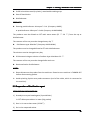
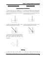
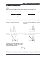
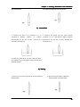
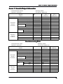
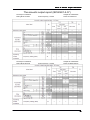
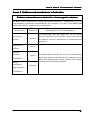
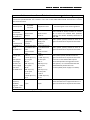
1
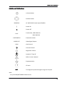
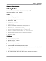
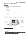
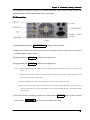
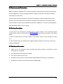
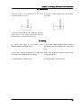
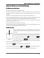
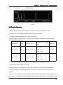
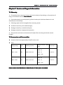
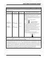
ODM-2100S
ULTRASONIC A/B SCANNER
FOR OPHTHALMOLOGY
USER’S MANUAL
Version 4.1
User's Manual
0
Contents
PRECAUTIONS................................................................................................................................................... i
WARNINGS........................................................................................................................................................ i
CAUTION.......................................................................................................................................................... ii
Labels and Indicators....................................................................................................................................... 1
Chapter 1. Introduction....................................................................................................................................2
1.1 General Description.......................................................................................................................... 2
1.2 Intended Use.....................................................................................................................................2
1.3 Contraindications.............................................................................................................................. 2
Chapter 2. Specifications..................................................................................................................................3
2.1 Working Conditions...........................................................................................................................3
2.2 B Mode..............................................................................................................................................3
2.3 A Mode..............................................................................................................................................3
2.4 Firmware........................................................................................................................................... 4
2.5 Safety................................................................................................................................................ 4
2.6 Storage and Transportation.............................................................................................................. 4
Chapter 3. Installation, Startup, Shutdown......................................................................................................5
3.1 Packing List........................................................................................................................................5
3.3 Environmental Requirements........................................................................................................... 5
3.4 Connection........................................................................................................................................6
3.5 Environmental Protection................................................................................................................. 7
3.6 Startup Procedure.............................................................................................................................7
3.7 Shutdown Procedure........................................................................................................................ 7
Chapter 4. Operation....................................................................................................................................... 8
4.1 Keypad Description........................................................................................................................... 8
4.2 Suggested Position of Patient, Operator and other near person....................................................10
4.3 B Mode............................................................................................................................................10
4.4 A Mode........................................................................................................................................... 14
4.5 Five-Point Marking Method............................................................................................................ 16
4.6 IOL Calculation................................................................................................................................ 19
4.7 Parameter Setup............................................................................................................................. 21
4.8 Image printing.................................................................................................................................22
Chapter 5. Cleaning, Disinfection and Sterilization........................................................................................23
5.1 How to prevent Cross-Infection...................................................................................................... 23
5.2 Sterilization Procedure – Pre-sterilization and Sterilization of the Probes..................................... 23
5.3 Preparation of Sterilization agent................................................................................................... 24
5.4 Standard method............................................................................................................................ 25
5.5 Method for high risk patients......................................................................................................... 28
Chapter 6. Maintenance and Trouble Shooting............................................................................................. 31
6.1 Maintenance of the Device.............................................................................................................31
6.2 Biometric Test................................................................................................................................. 31
6.3 Trouble Shooting.............................................................................................................................32
Chapter 7. Service and Support Information................................................................................................. 34
7.1 Warranty......................................................................................................................................... 34
7.2 Accessories and Consumables........................................................................................................ 34
Annex A Acoustic Output Information...........................................................................................................35
Annex B Guidance and manufacturer's declaration..................................................................................... 37
Annex C References....................................................................................................................................... 41
User's Manual
1
Precautions and Warnings
PRECAUTIONS
�
The instrument should be operated by trained doctors.
�
Please read the manual carefully before installation and operation
�
Please refer to chapter 5. Cleaning, Disinfection and Sterilization to avoid
cross-infection while using.
�
Unplug power supply before cleaning.
�
Please refer to chapter 6. for maintenance attentions.
WARNINGS
�
Do not make any modification to the Device without authorization.
�
The manufacturer won't be responsible for any damage or injury caused by any failure to
follow the instructions in the User's Manual
Manual.
�
The manufacturer reserves the right to modify equipment characteristics without
previous notice under FDA Laws and MDD (93/42/EEC) Regulation.
�
The quality guarantee of ODM-2100S will be invalid if it is opened (even partially),
modified or repaired in any way by anyone who is not authorized by the manufacturer.
____________________
�
This device is not intended for fetal use.
�
According to FDA laws, ODM-1000 is a prescription Device and is to be used by or under
the supervision of a licensed physician.
�
Disconnect AC power before cleaning the housing case.
�
While plugging in the robe, make sure the red mark on the probe align with the red mark
on the socket.
�
While plugging of the probe, please be sure you are pulling the connector instead of the
cable.
�
Do not scratch the surface of the probe.
�
Do not drop the probes
For any question, please contact the Manufacturer or your Local Distributor
User's Manual
i
Precautions and Warnings
CAUTION
HOW TO PREVENT CROSS-INFECTION
�
Between uses on different patients the probe must be cleaned to prevent
cross-infection.
�
Manufacturer advocates a preventive action and a cleaning procedure in Chapter 5.
Cleaning, Disinfection and Sterilization.
____________________
CAUTION
�
The ODM-2100S IOL calculator will calculate negative IOL values if such is predicted by
the data input.
�
These are displayed with a minus sign "-". Do not ignore this sign.
CAUTION
�
To preserve the equipment, avoid using any abrasive cleaner. If possible, clean spots
before they dry.
_____________________
TISSUE EXPOSURE TO ULTRASOUND ENERGY:
�
The ODM-2100S is designed for use in ophthalmology only.
�
While the manufacturer is not aware of any reports of adverse effects from using
ophthalmic ultrasound scanner, even at FDA pre-enactment levels, no other use is
intended or implied.
�
The system controls limit of the output energy within the parameters specified for its
intended purpose. Please refer to Annex A of User's Manual
Manual.
�
No control of ultrasound energy is available to the users other than the duration of
exposure, considering the current concern for possible unknown hazards, and despite
the extremely low output intensities used in this ultrasound system.
�
The manufacturer recommends that patients exposure time during measurement.
User's Manual
ii
Labels and Indicators
Labels and Indicators
A-Probe Socket
B-Probe Socket
POWER IN
AC 100V-240V Power Input, 50/60Hz
│
Power On
〇
Power Off
FUSE
FOOTSWITCH
VIDEO OUT
GAIN
Fuse Socket, 100V-200V:4A
200V-240V:2A
Footswitch socket
Video Signal Output
Gain Control
Contrast Control
Brightness Control
Symbol of "Type B"
Refer to User's Manual
Equipotentiality
CE mark
IPX7
The degree of protection against ingress of liquids
Note:
only for SONY/MITSUBISHI Video Printer.
User's Manual
1
Chapter 1. Introduction
Chapter 1. Introduction
1.1 General Description
ODM-2100S Ultrasonic A/B Scanner for Ophthalmology is an ultrasonic imaging instrument
specialized in ophthalmological diagnosis.
It consists of the main unit, 10MHz mechanical sector B-scan probe, 10MHz A-biometric
probe, built-in video monitor, and foldable keypad.
1.2 Intended Use
The device is intended to be used for ophthalmic ultrasonic diagnosis and measurement.
1.3 Contraindications
Eyelid trauma and severe eye infection patients are prohibited to use B scan and cornea
trauma, inflammation or infection patients are prohibited to use A-biometric Scan.
User's Manual
2
Chapter 2. Specifications
Chapter 2. Specifications
2.1 Working Conditions
Environmental temperature: 5°C~40°C, relative humidity: ≤ 80%.
Power supply: AC 100V~240V,50/60 Hz
2.2 B Mode
�
Ultrasonic frequency: 10MHz.
�
Scanning method: mechanical sector scan.
�
Gain control:
�
Display mode: B, B+B, B+A.
�
Gray scale: 256
�
Scanning scope: depth 31mm-63mm, scanning angle: 53º.
�
Resolution: axial
�
Accuracy of geometrical position: axial
�
Capacity of digital scan converter (DSC): ≥4 ×512×512×8 bit
�
Electronic caliper: electronic cursor for distance measurement,
�
Accuracy: 0.25mm.
98dB.
0.2mm, lateral
0.4mm
5%, lateral 10%
2.3 A Mode
�
Ultrasonic frequency: 10MHz.
�
Biometry accuracy:
�
Resolution: 0.01mm.
�
Measuring range (AL): 15-39mm.
�
Total gain: 98dB, user adjustable gain range: 0-55dB.
�
Measuring parameter: anterior chamber depth, lens thickness, vitreous length and axial
length.
�
Measuring method: automatic and manual
�
IOL power calculation: SRK-1, SRK/T, SRK-II, BINK/2, HOLLADAY and HOFFER-Q.
User's Manual
0.06mm.
3
Chapter 2. Specifications
2.4 Firmware
Firmware: 21SAB V1.20
2.5 Safety
In accordance to IEC 60601-1 and IEC 60601-2-37
2.6 Storage and Transportation
Storage Condition:
Packed device should be stored in a room of Temperature: -20℃~40℃; Relative humidity:
≤80%; No corrosive gas, well-ventilated.
Transportation:
The accessories such as Probe should be packed in to original package before transportation.
Severe impact and crash, rain and snow shall be avoided.
User's Manual
4
Chapter 3. Installation, Startup, Shutdown
Chapter 3. Installation, Startup, Shutdown
3.1 Packing List
Please check the components in the package according to the following list.
� Main Unit
1
� B Probe
1
� A Probe
1
� Foot Switch
1
� Power cord
1
� Fuse
2 (110V-120V: 4A; or 220V-240V:2A)
� Test Object
1
� User’s Manual
1
3.2 Main Parts of ODM-2100S
ODM-2100S consists of Main Unit, 10 MHz mechanical sector B Probe, 10 MHz A mode
biometric probe, built-in video monitor and foldable keypad. Its configuration is as below:
Fig 3-1
3.3 Environmental Requirements
The device should be operated in clean, dry and air-conditioned environment.
The power socket used must be with good grounding, otherwise it increases the risk of noise
as well as creepage.
� Do not use the equipment in locations subject to intense electric or magnetic fields.
Avoid excessive shock (e.g. tooth drill) and direct sunlight.
User's Manual
5
Chapter 3. Installation, Startup, Shutdown
The equipment should be placed on a stable worktable. Leave certain space around the
instrument and avoid soft object below it for ventilation.
3.4 Connection
Fig 3-2
1) Plug footswitch cable to
FOOT SWITCH
socket on the rear panel.
2) Plug power cable to the power socket on the rear panel and the other end to a properly
grounded power supply socket.
3) Plug B probe into
B-Probe
socket on the right panel.
4) Plug A probe into
A-Probe
socket on the right panel.
Note: 1) While plugging the probe, make sure the red mark on the probe aligns with the red mark on the
socket.
2) The probe should be placed in the probe holder. Do not put it on table or other supporters. Do
not scratch the surface of the probe.
3) While unplugging the probe, please hold the connector. Do not pull the cable.
4) If the probe drops while using or moving, please check the surface and shell carefully. If any of
them is broken, then stop using it immediately and contact the manufacturer or local distributor
for repairing.
5) If a video printer is available, connect the video cable to VIDEO IN of the printer, and the
other end to
User's Manual
VIDEO OUT
on the rear panel of the main unit.
6
Chapter 3. Installation, Startup, Shutdown
3.5 Environmental Protection
When the device is abandoned, it could be treated as usual Electronic products according to
the local Regulation. And its package should be treated as the plastic and paper materials
according to the local laws.
The gel bottle is made of polythene, and the remaining gel is water-soluble. Heavy metal
contents meet the requirements of cosmetic standard. The treatment of the empty bottle
should conform to the local environmental protection regulations. It can be treated together
with disposable plastics such as syringe
3.6 Startup Procedure
1. Check up all the connections including power cables, Probes. If not connected, please
connect them under the instruction of 3.4 Connection
Connection. And keep the probes in the probe
holder.
2. Start the Power socket, and then switch on the power switch on the rear panel of main
unit.
3. A few minutes later, you could see the single B mode interface on the screen, and now it
could start diagnosis.
3.7 Shutdown Procedure
1.
Make sure all the diagnosis result and data have been printed or transferred to your
workstation or computer.
2.
Put two probes back to the probe holder.
3.
Turn off the switch of main unit.
4.
Shutdown all the devices connected with ODM-2100S (Such as printer, workstation).
5.
Shutdown the power socket connected with ODM-2100S.
User's Manual
7
Chapter 4. Operation
Chapter 4. Operation
4.1 Keypad Description
The instrument can be operated by keypad and soft keys on the screen. The keypad consists
of alphabetic keys, numeric keys and functional keys. The soft keys are controlled by the
trackball and its left and right key
L
and
R
.
4.1.1 Alphanumerical keys
Letter, Number
Number:: The alphabetic and numeric keys are used to input characters in the place of
the cursor.
�, �, �, � Press them to input corresponding arrows in the place of the cursor.
� Backspace key. Press it to place the cursor one space back. At the same time the character
will be erased.
SPACE
Space key. To move the cursor to the right.
Enter key. It is used to finish the current line and go to the next line, or finish the
↵
current item and go to the next one.
+
-
To adjust the threshold of A-Scan measurement under A-Mode; while under the
interface of IOL and SETUP, can be used as just plus and minus.
4.1.2 Function Keys
B
Press it to enter single B scan.
B+A
Press it to enter B+ A mode.
B1
B2
A
Press them to enter double B scans and switch between images of B1 and B2.
Press it to enter A mode automatic measurement or to refresh A-scanning and start a
new measurement.
AUTO Automatic measuring key. Press it in the status of A automatic measurement, the
instrument will be shifted among NORM, APHA, SPEC and CATA.
User's Manual
8
Chapter 4. Operation
�
NORM
NORM: NORMAL EYES
�
SPEC
SPEC: SPECIAL EYES
�
APHA
APHA: APHAKIC EYES
�
CATA
CATA: DENSE CATARACT EYES
MANL
Manual measuring key. Press it to enter manual measurement of A mode.
IOL Press it to enter IOL calculation mode where calculation parameters can be input.
From A-Mode to IOL, the average axial length can be automatically put in AL box; while if an
appointed AL from 8 groups of results is necessary, press AL. Refer to AL below.
AL
Press it under IOL mode, the axial length pointed by “→” line that is measured
automatically in A mode can be input to AL box for IOL calculation.
CAL In IOL mode, press this key to calculate IOL after all constants are input correctly.
OS
OD
Indicate left or right eye which is displayed on the screen.
�
�
� Cursor control / function keys used to move the cursor and select functions.
�
� � In B mode, press it to turn the image page up and down and save 8 pages, marked as
P1-P8; in A mode, press it to display the curve of automatic measurement indicated by “→”;
In IOL mode, press it to retrieve the information of axial length, cornea curvature, etc.
FRZ/SCN
Scan/Freeze control key. Press it, the instrument shifts from START SCAN to
FREEZE IMAGE or from FREEZE IMAGE to START SCAN
SCAN. After 10 minutes of scanning, it is
frozen automatically to protect the probe.
4.1.3 Trackball
The trackball can be used to move the cursor on the screen. Press
functions where the cursor is; In B mode, press
R
L
to activate the
to display or hide the functional menu
on the right side of the screen.
4.1.4 Gain Control Knob
In B mode or A mode, the gain can be changed by adjusting this knob. Change of gain is
displayed on the screen at the same time: GN = xx dB.
4.1.5 Foot switch
User's Manual
9
Chapter 4. Operation
In B mode or A mode, the foot switch has the same function as
the start-up of the probe. When it is started,
SCN
FRZ/SCN
, i.e., controls
is on the screen: in B mode, the probe
waves and the image is displayed dynamically; in A mode, the probe indicator is on. When it
is frozen,
FRZ
is on the screen: in B mode, the probe stops and the image is still; in A
mode, the probe indicator is off.
4.2 Suggested Position of Patient, Operator and other near person.
In a usual measurement, it's better to let patient lie down and let his head close to the
device (less than 1.2m). The operator should take a position convenient for reach patient's
head and operating the device.
4.3 B Mode
Fig 4-1
In mode menu, SB: single B mode; B1/B2: double B images; B+A/A+B: B mode and A mode,
both B image and A waves displayed. Click the functional keys or the
L
key of the
trackball to enter the corresponding work mode. The screen displays as following (Fig 4-2):
User's Manual
10
Chapter 4. Operation
Fig 4-3 Single B Mode
Fig 4-4 Double B Mode
The upper one is B1 and the lower one is B2.
Select one of them and active it, then you
can scan, freeze, adjust the gain, label the
eye and save.
Press the ↑ ↓ keys to move the Sample
taking Line and A curve changes accordingly .
Fig 4-5: B+A Mode
4.3.1 Direction and Position Analysis
There is a white dot on one side of the probe end.
This dot always corresponds to the upper part of
the sector image. For instance, if the dot is above
the eye, marked as “↑”, the image on the screen
is the vertical section of that eye. The top of the
sector corresponds to the upper part of the eye,
and the bottom of the sector corresponds to the
lower part of the eye. Another example: if the dot
Fig 4-6
is on the nose side of the right eye, marked as
“→”, the image on the screen is the horizontal
section of the eye. The top of the sector is the nose side of the eye, and the bottom of the
sector is the temporal side of the eye.
User's Manual
11
Chapter 4. Operation
Move the cursor with the trackball to the probe position marker, press
L
key, the marker
will rotate clockwise; it rotates 45° every time it is pressed.
4.3.2 How to obtain a scan under B mode.
a) Select B mode.
b) Input patient information at the bottom of the screen.
Fig 4-7
c)
�
NAME: 13 digits of letters or numbers.
�
SEX: 6 digits of letters or numbers.
�
AGE: 3 digits of letters or numbers.
Label the eye to be examined. Press OD key for right eye; press OS key for left eye.
d) Let the patient lie on his/her back, slightly close the eyes.
e) Put some acoustic gel on eyelid; gently place the B probe on the eyelid.
f)
Push down the footswitch or press
FRZ/SCN , the probe starts scanning. The real
time ultrasonic sectional view of the eye will appear on the screen.
g) Adjust the total gain knob to make the focus clear and get a satisfactory image. Push
down the footswitch again or press
FRZ/SCN
to freeze the image. The collection
of ultrasonic B image is completed.
Note: Adjustment of gain control is one of the key operations that affecting B mode image quality.
For different conditions and diagnostic requirements, the gain adjustment is different. Make sure
do not fix the gain, however it is also not the case that the larger the gain, the better the image.
h) Press the �
� keys to save the current image and turn the page up and down.
Mark the image with
P1
,…,
P8 . 8 images can be saved at most
4.3.3 Function Menu
In B mode, press the
R
key of the trackball to show the functional menu; press any key
again to hide it. Select the functions with the trackball’s
User's Manual
L
key.
12
Chapter 4. Operation
a)
ZOOM
Depth control key. To change the scanning scope. 6 depths are available to
be adjusted. They are showed on the right upper screen as:
Press
�
DEPTH = 34 mm
�
DEPTH = 50 mm
�
DEPTH = 39 mm
�
DEPTH = 56 mm
�
DEPTH = 45 mm
�
DEPTH = 60 mm
←
b) PROC
→ to adjust the depth. It is effective after the scanning is activated.
Gray scale control and Post-image processing key. Press
←
→
keys to
select the post image processing mode: linear (LINE), logarithmic (LOG CURVE),
exponential (EXP CURVE) and S (S CURVE).
c)
TEXT
Full screen text labeling key. Move the cursor with the
L
key of the
trackball and enter the text to label the image.
d)
DIST
Distance Measuring key. Select DIST and activate double cursor distance
measuring status, a “++” appears on the screen. Move the “++” to the position where
you want to start measuring, then press the
L
key of the trackball, the current “++”
will be locked. Move the trackball again, another “++” is shown up. Move it to the
terminal of measuring and press
L
key again to complete the measurement. The
distance between two “++” will appear on the screen. The unit is “mm”. If another
measurement is needed, repeat the above procedure.
e)
AREA
L
Area measuring key. Press
of an area with the trackball. Press
L
key to fix a start point and draw the outline
key again to get the area measurement result.
Multiple measurements can be made and the unit is mm2.
f)
CLRS
g)
NEW
To clear all the labels and measuring results on the image.
New patient. Clear the previous patient’s information, temporarily save
ultrasonic B images and get prepared for the next examination.
h)
EXIT
User's Manual
To exit function menu.
13
Chapter 4. Operation
4.4 A Mode
Ultrasonic A Biometry is used to measure the anterior chamber depth, lens thickness,
vitreous length and to calculate the axial length according to these measurements. To ensure
the accuracy, the ultrasound should go into the eye from the vertex of the cornea as close as
possible, and superpose with the axis.
Auto and manual modes can be selected for the measurement. Auto mode is suitable for
normal, aphakic, dense cataract and other conditions, where the velocity of ultrasound is
known.
For contact method, A probe is contacted with the cornea vertex directly. This method is
simple and easy to control. But the cornea can be injured and slightly distorted, therefore
affecting the results. So the operator should operate very carefully and not press the cornea.
The contact method applies to both the auto and manual mode.
When A Scan is selected, it enters the following screen (Fig 4-8).
Fig 4-8
�
NORM
Normal Eye, Auto
�
AC
Anterior Chamber Depth
�
APHA
Aphakic, Auto
�
LENS
Thickness of Lens
�
SPEC
Special Eye, Auto
�
VITR
Vitreous Length
�
CATA
Dense Cataract, Auto
�
AL
Axial Length
�
MANL
Manual
�
AV
Average Measuring Result
�
COR
Thickness of Cornea
�
SD
Standard Deviation
4.4.1 Auto Measuring
User's Manual
14
Chapter 4. Operation
(1) Press
A
to enter A scan auto measuring mode (NORM).
(2) Select the type of eye among NORM, APHA, SPEC, CATA.
(3) Let the patient lie on his/her back and open both eyes. Anaesthetize the eye to be
measured.
(4) Sterilize the front part of A probe with chloramphenicol eyedrop.
(5) Push down the footswitch or press the
�
FRZ/SCN
to start scanning.
Let the patient stare at the probe and put the probe on the cornea vertex
gently.
(6) Adjust the gain control to get the satisfactory wave.
(7) When you hear a series of beep sound, the result comes out and is displayed on the
screen. If the beeps are not heard, move the probe slightly until beeps heard and
the measuring is completed. Measuring is undertaken one by one automatically
until eight groups of data are achieved or it can be stopped when FRZ/SCN
is
pressed to freeze the image. Eight groups of data can be achieved from each
patient at most, and the operator decides how many groups of data are needed.
Note: Since auto measuring result is calculated by averaging multiple operations, the operator
needs to handle the probe gently and stably. The image can be frozen and the probe be taken
away only after the beeps stop and the result appears on the screen.
Check the results & Delete unreliable data: If the measuring results are obviously unreliable,
delete them. Press � � keys to move the cursor “→”” to the line that needs to be deleted
and click
DEL
with the trackball’s
L
key. The next line moves up and average value is
recalculated.
Fig 4-8 A waveform with contact method
Please delete the results in the following situations:
User's Manual
15
Chapter 4. Operation
�
Position marker does not correspond with the top of the wave.
�
The retina wave is not sharp.
�
There is a big difference between the measuring and the average.
(8) Label the eye.
OS
for left eye;
OD
for right eye.
Clear the current result and start a new measurement. Repress
with
L
A
key or click
NEW
key of the trackball
4.4.2 Manual Measuring
In some circumstances, it is difficult to get the result by automatic biometry or patients have
difficulties to cooperation with the operator. In these cases, manual biometry is selected;
otherwise, it is not preferred. Press MANL to enter manual measurement.
Operating steps are similar to the automatic measurement. Press
scanning, adjust gain control and get a satisfactory wave. Press
FRZ/SCN
FRZ/SCN
to start
to freeze the
wave, mark and measure it with the trackball. The operation refer to 4.5 Five-Point Marking
Method
Method.
Fig 4-9: Waveform captured manually.
4.5 Five-Point Marking Method
When a bundle of ultrasounic goes through optic axial, we can get ultrasonic reflex from five
different layers (Fig 4-10), including: (1) cornea vertex; (2) back of cornea; (3) front of lens; (4)
back of lens; (5) retina.
User's Manual
16
Chapter 4. Operation
Fig 4-10: five-point marking
Due to the specialty of eye structure, ultrasonic velocity becomes different when going
through different tissues as follows:
Velocity of cornea:
Vcor = 1620 m/s
(1) – (2)
Velocity of anterior chamber:
Vac = 1532 m/s
(2) –(3)
Velocity of lens:
Vlen = 1641 m/s
(3) – (4)
Velocity of vitreous:
Vvitr = 1532 m/s
(4)—(5)
Axial length: AL = Vcor * (t2-t1) + Vac*(t3-t2) + Vlen *(t4-t3) + Vvitr *(t5-t4).
(1.1)
As long as the five special points can be marked precisely, we can then figure out accurate
axial length according to (1.1). This is what we called Five-Point Marking method for axial
length measurement
4.5.1 Use of Five-Point marking method under B+A mode for axial length measurement.
(1) Press B+A key to enter B+A mode, see Fig 4-11.
(2) Scan the eyeball, then freeze it once satisfied image is obtained;
(3) Move trackball, press >>> area on screen with L key of the trackball, then enter Five-Point
marking stage;
(4) Move the cursor to A curve at the bottom of the screen, press L key of the trackball to
mark the five points;
Note: ODM-2100S has only contact mode for A measurement, it is hard to recognize vertex and back of
cornea, so points (1) and (2) should both be put on (1). Vertex and back of cornea can be recognized
seperately on A measurement when immersion mode is available.
(5) After marking the 5th point, the result of axial length will be shown on top of the screen.
Note: Velocity between points can be set up in SETUP menu (press SPEC
SPEC, input velocity of cornea, lens
SAVE
and vitreous, then click on SAVE)
User's Manual
17
Chapter 4. Operation
Fig 4-11
Fig 4-12
4.5.2 Use of Five-Point marking method under A mode for Axial length measurement
(1) Press A to enter A mode;
(2) Choose measuring mode: (NORM, APHA, SPEC, CATA);
(3) Place A probe onto patient’s cornea, start foot switch and undertake an automatic
measurement;
(4) When standard deviation, S.D, is not clinically satisfied, Five-Point marking can be
corrected.
(a) Press �
� key to see A scan waves, remark the ones are not satisfied;
(b) Move trackball, press >>> area on screen with L key, then enter Five-Point marking stage;
(c) Move the cursor to A curve at the bottom of the screen, press L key of the trackball to mark the
five points, (if it is hard to recognize vertex and back of cornea, points (1) and (2) can both be put on
(1));
(d) After marking the 5th point, the measurement result, average of axial length and S.D will all be
recaculated according to the new marking. See Fig 4-12.
Note: Velocities under different measuring modes:
NORM (Normal):
� Velocity of cornea:
Vcor = 1620 m/s
(1) – (2)
� Velocity of anterior chamber: Vac = 1532 m/s
(2) –(3)
� Velocity of lens:
Vlen = 1641 m/s
(3) – (4)
� Velocity of vitreous:
Vvitr = 1532 m/s
(4)—(5)
Vcor = 1620 m/s
(1) – (2)
� Velocity of anterior chamber: Vac = 1532 m/s
(2) –(3)
CATA (dense cataract):
� Velocity of cornea:
User's Manual
18
Chapter 4. Operation
� Velocity of lens:
Vlen = 1629 m/s
(3) – (4)
� Velocity of vitreous:
Vvitr = 1532 m/s
(4)—(5)
Velocities under modes of SPEC (special), MANL (manual), APHA (aphakic) can be set up in
SETUP menu.
After reset the velocities, press <<< under A mode, the results will be recalculated
accordingly.
+
-
can be used to adjust the threshold of A-scan measurement.
4.6 IOL Calculation
4.6.1 Velocity Setup
The velocity refers to the spread velocity of the ultrasound within the eye. This instrument
has four eye modes: NORM (normal), APHA (aphakic), SPEC (special) and CATA (dense
cataract). The parameters are as follows
Unit: m/s
Vac
Vlen
NORM
1532
APHA
---
SPEC*
1532*
CATA
1532
**
1641
__
PMMA: 2718
Acrylic: 1946
Silicon: 1050
Vvitr
1532
1532*
7 Parameter Setup
*: To modify the velocity in the parameter setup function, refer to 4.
4.7
Setup.
**:Provided by IOL manufacturer
1629
1532
4.6.2 Constant of Formulae
6 groups of IOL calculation formulae are provided: SRK_II, SRK_T, BINK_II, HOLLADAY,
HOFFER_Q, HAIGIS. Different constants are used for different formula, recorded as A or ACD
or SF, which are provided by IOL manufacturers. They can be modified and saved in the
parameter SETUP function. For details, refer to 4.6.
BINK-II and HOFFER-Q use ACD, i.e., the desired anterior chamber depth constant. ACD can
also be calculated from constant A:
ACD = [((A × 0.5663) - 65.60) + 3.595] / 0.9704
or ACD = (SF + 3.595) / 0.9704
HOLLADAY uses SF,can also be calculated from constant A:
User's Manual
19
Chapter 4. Operation
SF = (A × 0.5663) - 65.60
or SF = (ACD × 0.9704) - 3.595
The shift from A to SF is completed automatically after constant A is entered.
SRK-II and SRK-T use A, can be calculated from the following formula:
A = (SF + 65.60) / 0.5663
or A = 109.49 + (1.71358 × ACD)
HAIGIS uses three constants: a0, a1, a2, can be calculated from A:
a0 = (0.62467 × A) - 72.434
a1 = 0.40
a2 = 0.10
4.6.3 IOL Calculation steps
a) Press
IOL
to enter the calculation mode.
b) Select formula with the
c)
L
key of the trackball.
Enter correct parameters.
AL = Axial Length
K1, K2 = Keratometry
DR = desired Refraction
When calculation mode is entered, the
average of axial length calculated is put in AL.
Press AL key to input the axial length from the
line where the cursor “→” is located.
Move the cursor “_” with arrow key and
enter key to input numbers required.
Fig 4-13
d) Modify and save constants A or ACD in the parameter SETUP function. See 4.6.
�
IOL type needs to be selected for formula BINK-II: anterior or poserior. Click ANTI
or POST with
User's Manual
L
key of the trackball.
20
Chapter 4. Operation
� Anterior chamber depth AC needs to be input for formula HAIGIS. The automatically
calculated average anterior chamber depth is put in AC in calculation status. Press AL
key, the anterior chamber length from the line where the cursor “→” is located is input.
If it is required to enter manually, move cursor “_” to AC and enter the numbers.
e) Enter patient informaiton, label the eye.
f)
CAL
Press
the calculation will be completed and listed on the screen.
DEM
Diopter of emmetropia
(D)
DAM
Diopter of ametropia
(D)
IOL
Diopter of IOL
(D)
REFR
Refraction after implant (D)
Each group of AL, K1, K2, REFR, etc. can be calculated by different formulae in order to be
compared with each other .
g) The parameters and measured results can be saved as a record by click SAVE with L key of
the trackball. “REC= XX” is showed at the right upper corner of the screen. To
review the records, press � � . 50 records can be saved in total.
4.7 Parameter Setup
Click
MENU
select
SETUP
on the left upper corner of the screen with the
L
key of the trackball,
to enter.
Move the cursor “_” with arrow key and enter key to enter the number where the “_” is.
Fig 4-14
User's Manual
21
Chapter 4. Operation
Click on
IOL CONST
with
L
of the trackball and setup IOL constants: A and ACD. There
are two groups: LEFT and RIGHT
RIGHT, for left and right side IOL calculation respectively. The
number after CURRENT tells which group is active. DR is desired refraction after surgery.
The constants setup by the manufacturer are:
Click on
�
LEFT 1
A = 115.3
ACD = 3.39
�
RIGHT 1
A = 116.6
ACD = 4.15
�
LEFT 2
A = 117.9
ACD = 4.91
�
RIGHT 2
A = 118.7
ACD = 5.37
�
CURRENT = 1
SPEC
with
L
key of the trackball to set the velocity. When aphakic (APHA) or
special (SEPC) eyes are measured, the velocity in the anterior chamber, lens and vitreous
body can be set manually. For the velocity in IOL, consult the manufacturer.
V(A) : velocity in anterior chamber (m/s)
V(L) : velocity in lens (m/s)
V(V) : velocity in vitreous body (m/s)
After setup, press
SAVE
to save permanently. The parameters will be effective when the
instrument is turned on next time.
Click
TIME
with
L
key of the trackball to set the time. The format is mm-dd-yy,
hh-mm with 24-hour system. Click
TIME
again to save.
4.8 Image printing
If a video printer is available, all images and characters on the screen can be printed by
simply pressing PRINT key on the printer. Please read the user’s manual of the printer for
details.
User's Manual
22
Chapter 5. Cleaning, Disinfection and Sterilization
Chapter 5. Cleaning, Disinfection and Sterilization
5.1 How to prevent Cross-Infection
The surface of the probe must be always clean, which can be cleaned with soft tissue after
each use.
Front part of the probe may be washed with distilled water, physiological saline water,
alcohol, chloramphenicol eye drop or Cidex liquid disinfectant, which are usually found in
hospitals. Other FDA-cleared disinfectants may also be used.
�
The probe can be immersed.
�
Do not immerse the connector.
�
Do not autoclave the probes.
�
After cleaning, rinse the end of the probe thoroughly with clean water to remove all
traces of the liquid used.
�
Follow the instruction on the label of commercial disinfectants.
�
The surface should then be dried with lint-free cloth.
5.2 Sterilization Procedure – Pre-sterilization and Sterilization of the Probes
Forward:
---- Operator should use standard method to ensure satisfactory sterilization of the probe
after use.
---- Operator should use risky-patient protocol to ensure satisfactory sterilization of the
probe every time after use on a patient where there is a risk of infection of Creutzfeld-Jacob
disease.
OPERATOR
OPERATOR’’S CLOTHING
� One-off overall.
� Disposable gloves, sterile for sterilization.
� Glasses and anti-rejection masks.
EQUIPMENT
� Soft silk brush (surgical nail brush)
User's Manual
23
Chapter 5. Cleaning, Disinfection and Sterilization
� 3×500 ml stainless steel (or plastic), autoclavable-soaking trays.
� One-off hand cloths.
� Distilled water.
PRODUCTS
� Cleaning-predisinfectant: Aniosyme ® P.L.A. (Company: ANIOS),
or predisinfectant: Alkazyme ® alcalin (Company: ALKAPHARM).
The products must be diluted at 0.5% with warm water (25 ℃ -30 ℃ ) from the tap or
distilled water.
The contents of the tray must be changed every day.℃
�
Disinfectant type Alkacide ® (Company ALKAPHARM).
The product must be changed diluted at 5% with distilled water.
The solution must be changed every day.
� 6 Chlorometric degree solution of sodium hypo chloride at 20 ℃.
The contents of the tray must be changed after each use.
� Demineralized or distilled water.
NOTES:
� Please disconnect the probes from the machines. Please be sure machine is TURNED OFF
before disconnecting probes.
� Avoid splashing liquids onto probe connectors (end of the cable, which is connected to
the machine).
5.3 Preparation of Sterilization agent
STERILIZATION-PREDISINFECION
1) Proteolytic enzyme based agents (2 possibilities)
1-0.5% Alkazyme solution in water (20g sachet)
2) Pour in 1L warm clean water (25-30℃)
3) Put in the unopened sachet.
User's Manual
24
Chapter 5. Cleaning, Disinfection and Sterilization
4) Wait for 1 minute.
5) Pour in 4 L water and stir it.
The Alkazyme solution can be used within 8 days if kept in sealed flasks. The solution can
also be made up in a 4L recipient using demineralized or distilled water fill up the soaking
tray from there.
OR:
---- 1-0.5% Aniozyme solution in water (25g sachet):
1) Pour in 1L warm water (25-30℃)
2) Put into the unopened sachet.
3) Wait for 1 minute
4) Pour in 4L warm water and stir.
nt
Sterilization Age
Agen
1) ---- 1-0.5% Alkacide solution in water:
2) Pour 5L distilled in flask
3) Pour in the Alkacide
4) Stir it
The Alkacide solution can be used within 8 days if kept in sealed flask.
Please pour in soaking tray (500ml) when sterilization is necessary.
Replacing Contents Of soaking trays
For frequent use, the contents of the trays should be replaced at the beginning of the
morning and beginning of the afternoon.
Wait 10 minutes after the last sterilization before emptying out the Alkazyme or Aniozyme
solutions.
5.4 Standard method
NOTES:
Please disconnect the probes from the machines. Machines must be turned off first.
Please avoid splashing any liquid onto the electrical connectors.
User's Manual
25
Chapter 5. Cleaning, Disinfection and Sterilization
Sector scan “B” type probe
“A scan” type probe
A) Decontamination-Predisinfection
1. Immerse the first 5 cm maximum in a
solution of either Alkazyme or Aniozyme for
5 to 15 minutes depending on the perceived
level of risk.
1. Immerse the probe and the cable (except
the connector) in the solution of Alkazyme
or Aniozyme for 5 to 15 minutes depending
on the perceived level of risk.
2. Clean the probe and the cable in the 2. Clean the probe and the cable in the
solution with the brush for 1 minute.
solution with the brush for 1 minute.
3. Clean the rest of the probe body and the
cables using a swab lightly dampened with
the same solution. Do not wet the
connectors.
B) Rinsing
4. Rinse the end of the probe in 3. Rinse the probe and the cable in
demineralized or distilled water. Do not wet demineralized or distilled water. Do not wet
User's Manual
26
Chapter 5. Cleaning, Disinfection and Sterilization
the connectors
the connectors.
5. Dip the probe up to A maximum of 5 cm
in the Alkacide solution for 5 to 20 minutes
depending on the estimated level of risk. Do
not wet the connectors.
4. Immerse the probe and the cable in the
Alkacide solution for 5 to 20 minutes
depending on the estimated level of risk.
Please keep the connectors dry.
6. Clean the probe body and the cable that
were not soaked using a wipe lightly
dampened with the Alkacide solution. Keep
the connectors dry.
C) Drying
7. Rinse the end of the probe with 5. Rinse the end of the probe with
demineralized or distilled water. Keep the demineralized or distilled water. Keep the
connectors dry.
connectors dry.
8. Dry it with a sterile compress.
6. Dry it with a sterile compress.
9. The B probe is ready for use.
7. The A probe is ready for use.
User's Manual
27
Chapter 5. Cleaning, Disinfection and Sterilization
5.5 Method for high risk patients
NOTES:
Please disconnect the probes from the machines. Machines must be turned off first.
Please avoid splashing any liquid onto the electrical connectors.
Sector-scan “B” type probe
“A scan
scan”” type probe
A) Decontamination –Pre
Pre--disinfection
1. Immerse the first 5 cm maximum in a solution of 1. Immerse the probe and the cable (except
either Alkazyme or Aniozyme for5 to 15 minutes connector) in a solution of Alkazyme or Aniozyme
depending on the percreived level of risk.
for 5 to 15 minutes depending on the perceived
level of risk.
2. Clean the end of the probe in the chosen 2. Clean the probe and the cable in the Chosen
solution for 1 minute using the brush.
solution for 1 minute using the brush
3. Clean the rest of the probe body and the cables
using a swab lightly dampened with the same
solution.. Do not wet the connector.
B) Rinsing
4. Rinse the end of the probe in 3. Rinse the probe and the cable with
demineralized or distilled water. Do not wet demineralized or distilled water. Please do
User's Manual
28
Chapter 5. Cleaning, Disinfection and Sterilization
the connectors.
not splash liquid onto the connector.
C) Inactivation
5. Immerse the first 5 cm maximum in a 6 4. Immerse the probe and the cable (except
chlorometric
degree
solution
of
sodium connector) in a 6 chlorometric degree solution
hypochloride for 60 min. at 20℃ ensuring the hypochloride for 60 min. at 20℃ keeping the
connectors are kept dry.
connectors dry.
6. Clean the probe body and the cable that were
not soaked using a wipe lightly dampened with the
Alkacide solution
D) Rinsing
7. Rinse the end of the probe with demineralized or
distilled water.
User's Manual
5. Rinse the probe and the cable with
demineralized or distilled water.
29
Chapter 5. Cleaning, Disinfection and Sterilization
E) Disinfection
8. Dip the probe up to a maximum of 5 cm in the 6. Dry with a sterile compress if the rinsing water
Alkacide solution for 15 min.
was sterile.
9. Clean the probe body and the cable that were not
soaked using a wipe lightly dampened with the
Alkacide solution. keep the connectors dry.
F) Rinsing
10. Rinse the end of the probe with 7. Rinse the probe end with demineralized
demineralized or distilled water.
or Distilled water keeping the connectors
dry.
11. Dry with a sterile compress or a single use 8. Dry with a sterile compress if the rinsing
dry wipe if the rinsing water was sterile
water was sterile
12. The B probe is ready for use
User's Manual
9. The A probe is ready for use.
30
Chapter 6. Maintenance and Trouble Shooting
Chapter 6. Maintenance and Trouble Shooting
6.1 Maintenance of the Device
Main power socket must be with good grounding.
The main unit should not be used for a long time, normally not more than 4 hours
continuously. While no measurement is done, the instrument should be in the state of
freezing.
Avoid collision and falling of the probe. Keep the top surface of the probe clean.
None corrosive detergent is allowed to clean the housing. Avoid water and liquid get into the
housing and external keyboard. Only a mild detergent may be used with soft cloth.
In humid area and season, if the instrument is not used for a long time, it should be
power-on for two hours per month.
Don't shake and fall off the instrument when moving.
All parts should be put into the original package in case of moving, especially the probe.
Therefore, the original package should be kept properly.
6.2 Biometric Test
There is a test object available with each equipement which imitates four
acoustical reflect interfaces of human eyes and used to test the biometric
measuring.
Fill the object with distilled water. Be sure that there is no air bubble in
the water. Gently place A probe onto the highest stage perpendicularly
in the object (see left drawing). Press
Fig 6-1
A
to enter A-scan and MANL to
enter manual mode. Click on FRZ/SCN to start scanning; move the probe
gently, adjust the gain properly to make the start wave and 3 reflected
waves clear and sharp as shown as Fig 6-2.
At this time, press AUTO key, the result will be seen automatically.
Keep the position of the probe, press
A
and then FRZ/SCN , the test can be restarted. If
the measuring results are repeatable, it means A-biometric scan is working properly.
User's Manual
31
Chapter 6. Maintenance and Trouble Shooting
Fig 6-2
6.3 Trouble Shooting
1) Light indicator of the power supply is not on and the instrument doesn’t work.
―Check if the power supply plug and socket are well connected.
―Unplug the power and check if the fuse is burnt out.
The fuse is 4A Fuse (110V-120V) or 2A Fuse (220V-240V). Be always sure to use the same
standard product as below.
Voltage Range
Spec.
Breaking Capacity
Testing Current / Blow
Dimension
Time
100% - 4h
100V~120V
4A
200A at 250 V AC
135% - 1h
5×20 mm
200% - 120s
100% - 4h
200V~240V
2A
100A at 250 V AC
135% - 1h
5×20 mm
200% - 120s
2) Main unit is working, but the monitor is not active or not displayed correctly.
―Check if the probe is well connected.
If above operation is not effective, please don’t open the housing without authorization.
Contact the supplier immediately. Explain the problems in detail for proper and in time
support.
The scanner is a high-tech product designed elaborately. Only qualified trained engineers are
authorized to repair the instrument. We are not responsible for problems caused by any kind
User's Manual
32
Chapter 6. Maintenance and Trouble Shooting
of unauthorized repair.
If required, we can provide the complete maintenance and repair manual to the authorized
qualified engineers of service stations.
User's Manual
33
Chapter 6. Maintenance and Trouble Shooting
Chapter 7. Service and Support Information
7.1 Warranty
1) The product has a warranty of one year from the date of purchasing, on the premise of
using in accordance with the User's Manual
Manual.
2) If the device does not work properly, please contact your local manufacturer or the
manufacturer immediately.
3) Following repairs will be charged within warranty period:
�
Problems caused by man-made damages;
�
Damages caused by unauthorized repair;
�
Damages caused by inappropriate operation.
4) We provide continuous maintenance and repair after warranty period with certain
charges.
7.2 Accessories and Consumables
�
Acoustic Gel all that approved by FDA/EC can be used.
�
Fuse
Voltage Range
Spec.
Breaking Capacity
Testing Current / Blow
Dimension
Time
100% - 4h
100V~120V
4A
200A at 250 V AC
135% - 1h
5×20 mm
200% - 120s
100% - 4h
200V~240V
2A
100A at 250 V AC
135% - 1h
5×20 mm
200% - 120s
Please contact local distributor or Manufacturer if other parts are needed.
User's Manual
34
Annex A Acoustic Output Information
Annex A Acoustic Output Information
Transducer Mode: B-Probe
Operating: B-Mode
Application: Ophthalmic
Test Standard: NEMA-1997
Acoustic
Output
Global Maximum Value
Pr.3
(MPa)
W0
(mW)
fc
(MHz)
Associated
Zsp
(cm)
Acoustic
Beam
x-6
(cm)
Parameter
dimensions
y-6
(cm)
PD
(μsec)
PRF
(Hz)
EBD
Az
(cm)
Ele
(cm)
MI
ISPTA.3
(mW/cm2)
0.097
0.315
10.6
2.10
ISPPA.3
(mW/cm2)
0.0375
3.50
0.0186
10.6
0.0186
10.6
2.10
0.0658
0.0662
0.138
2760
0.138
2760
1.80
1.80
Operating
Control
Conditions
Non-Autoscanning Mode
Transducer Mode: A-Scan
Operating: A-Mode
Application: Ophthalmic
Acoustic
Output
Global Maximum Value
Pr.3
(MPa)
W0
(mW)
fc
(MHz)
Associated
Zsp
(cm)
Acoustic
Beam
x-6
(cm)
Parameter
dimensions
y-6
(cm)
PD
(μsec)
PRF
(Hz)
EBD
Az
(cm)
Ele
(cm)
Test Standard: NEMA-1997
MI
0.160
0.525
10.8
1.40
ISPTA.3
(mW/cm2)
0.0136
ISPPA.3
(mW/cm2)
11.2
6.18E-4
10.8
1.40
0.133
0.121
6.18E-4
10.8
1.40
0.133
0.121
0.121
10.0
0.121
10.0
0.00
0.00
Operating
Control
Conditions
User's Manual
35
Annex A Acoustic Output Information
The acoustic output report (IEC60601-2-37)
Test Report #: 20090101
Testing Mode: A-Mode
Sample SN: 2008YP355
Probe Frequency: 10 MHz
Test Report #: 20090101
Testing Mode: B-Mode
User's Manual
Probe SN: 0508-5716
Sample SN: 2008YP355
Probe Frequency: 10 MHz
Probe SN: B558-085312
36
Annex B Guidance and manufacturer's declaration
Annex B Guidance and manufacturer's declaration
Guidance and manufacturer
manufacturer’’s declaration - electromagnetic emissions
The ODM-2100S ULTRASONIC A/B SCAN FOR OPHTHALMOLOGY is intended for use in the
electromagnetic environment specified below. The customer or the user of the ODM-2100S
should assure that it is used in such an environment.
Emissions test
RF emissions
CISPR 11
compliance
Electromagnetic environment-guidance
Group 1
The ODM-2100S uses RF energy only for its internal
function. Therefore, its RF emissions are very low and are
not likely to cause any interference in nearby electronic
equipment.
RF emissions
CISPR 11
Harmonic
emissions
Class A
Class A
IEC 61000-3-2
Voltage
fluctuations/
The ODM-2100S is suitable for use in all establishments
other than domestic and those directly connected to the
public low-voltage power supply network that supplies
buildings used for domestic purposes.
Complies
flicker emissions
IEC 61000-3-3
User's Manual
37
Annex B Guidance and manufacturer's declaration
Guidance and manufacturer
manufacturer’’s declaration - electromagnetic immunity
The ODM-2100S ULTRASONIC A/B SCAN FOR OPHTHALMOLOGY is intended for use in the electromagnetic
environment specified below. The customer or the user of the ODM-2100S should assure that it is used in
such an environment.
Immunity test
IEC 60601
test level
Electrostatic
discharge (ESD)
IEC 61000-4-2
±6 kV contact
±8 kV air
±6 kV contact
±8 kV air
±2 kV for power
supply lines
±1 kV for
input/output lines
±1 kV differential
mode
±2 kV common
mode
<5% UT
(>95% dip in UT)
for 0.5 cycle
40% UT
(60% dip in UT)
for 5 cycles
70%UT
(30% dip in UT)
for 25 cycles
<5% UT
(>95% dip in UT)
for 5 s
±2 kV for power
supply lines
±1 kV for
input/output lines
± 1 kV differential
mode
±2 kV common
mode
<5% UT
(>95% dip in UT)
for 0.5 cycle
40% UT
(60% dip in UT)
for 5 cycles
70%UT
(30% dip in UT)
for 25 cycles
<5% UT
(>95% dip in UT)
for 5 s
Electrostatic
fast
transient/burst
IEC 61000-4-4
Surge
IEC 61000-4-5
Voltage dips,
short
interruptions
and voltage
variations on
power supply
input lines
IEC 61000-4-11
Compliance level
Electromagnetic environment-guidance
Floors should be wood, concrete or ceramic
tile. If floors are covered with synthetic
material, the relative humidity should be at
least 30%.
Mains power quality should be that of a
typical commercial or hospital environment.
Mains power quality should be that of a
typical commercial or hospital environment.
Mains power quality should be that of a
typical commercial or hospital environment.
If the user of the ODM-2100S requires
continued operation during power mains
interruptions, it is recommended that the
ODM-2100S be powered from an
uninterruptible power supply or a battery.
Power
Power frequency magnetic field should be at
frequency
levels characteristic of a typical location in a
(50/60Hz)
3 A/m
3 A/m
typical commercial or hospital environment.
magnetic field
IEC 61000-4-8
Note: UT is the A.C. mains voltage prior to application of the test level.
User's Manual
38
Annex B Guidance and manufacturer's declaration
Guidance and manufacturer
manufacturer’’s declaration-electromagnetic immunity
The ODM-2100S ULTRASONIC A/B SCAN FOR OPHTHALMOLOGY is intended for use in the electromagnetic
environment specified below. The customer or the user of the ODM-2100S should assure that it is used in
such an environment.
IEC 60601
Compliance
Immunity test
Electromagnetic environment-guidance
test level
level
Portable and mobile RF communications
equipment should be used no closer to any part of
the ODM-2100S, including cables, than the
recommended separation distance calculated from
the equation applicable to the frequency of the
transmitter.
Recommended separation distance
d = 3.5 p
d = 1.2 p
80MHz to 800MHz
Conducted RF
3 Vrms
d = 2.3 p
800MHz to 2.5GHz
IEC 61000-4-6
150kHz to 80MHz 1 Vrms
where P is the maximum output power rating of
the transmitter in watts (w) according to the
transmitter manufacturer and d is the
Radiated RF
3 V/m
3 V/m
recommended separation distance in miters (m).
IEC 61000-4-3
80MHz to 2.5GHz
Field strengths from fixed RF transmitters, as
determined by an electromagnetic site survey, a
should be less than the compliance level in each
frequency range. b
Interference may occur in the vicinity of
equipment marked with the following symbol:
Note 1: At 80 MHz and 800 MHz, the higher frequency range applies.
Note 2: these guidelines may not apply in all situations. Electromagnetic propagation is affected by
absorption and reflection from structures, objects and people.
a
Field strengths from fixed transmitters, such as base stations for radio (cellular/cordless) telephones
and land mobile radios, amateur radio, AM and FM radio broadcast and TV broadcast cannot be
predicated theoretically with accuracy. To assess the electromagnetic environment due to fixed RF
transmitters, an electromagnetic site survey should be considered. If the measured field strength in the
location in which the ODM-2100S is used exceeds the applicable RF compliance level above, the
ODM-2100S should be observed to verify normal operation. If abnormal performance is observed,
additional measures may be necessary, such as re-orienting or relocating the ODM-2100S.
b
Over the frequency range 150KHz to 80 MHz, field strengths should be less than 1 V/m.
User's Manual
39
Annex B Guidance and manufacturer's declaration
Recommended separation distances between portable and mobile RF communications
2100S ULTRASONIC A/B SCAN FOR OPHTHALMOLOGY
equipment and the ODMODM-2100S
The ODM-2100S is intended for use in an electromagnetic environment in which radiated RF disturbances
are controlled. The customer or the user of the ODM-2100S can help prevent electromagnetic interference
by maintaining a minimum distance between portable and mobile RF communications equipment
(transmitters) and the ODM-2100S as recommended below, according to the maximum output power of
the communications equipment.
Separation distance according to frequency of transmitter
Rated maximum output
power of transmitter
w
m
150kHz to 80MHz
d = 1.2
p
80MHz to 800MHz
d = 1.2
p
800Mhz to 2.5GHz
d = 2.3
0.01
0.35
0.12
0.23
0.1
0.11
0.38
0.73
1
3.5
1.2
2.3
10
11
3.8
7.3
100
35
12
23
p
For transmitters rated at a maximum output power not listed above, the recommended separation distance
d in meters (m) can be estimated using the equation applicable to the frequency of the transmitter, where
p is the maximum output power rating of the transmitter in watts (m) according to the transmitter
manufacturer.
NOTE 1: At 80MHz and 800MHz, the separation distance for the higher frequency range applies.
NOTE 2: These guidelines may not apply in all situations. Electromagnetic propagation is affected by
absorption and reflection from structures, objects and people.
User's Manual
40
Annex C References
Annex C References
� HAIGIS W: Biometrie, in: Augenärztliche Untersuchungsmethoden, Straub W, Kroll P,
Küchle HJ (Hrsg), F.Enke Verlag Stuttgart, 255-304, 1995
� RETZLAFF J: A new intraocular lens calculation formula, Am Intra-Ocular Implant Soc J
6:148-152, 1980
� RETZLAFF J, SANDERS DR, KRAFF MC: Development of the SRK/T intraocular lens implant
power calculation formula. J Cataract Refract Surg 16 (3):333-340, 1990
� SANDERS DR, KRAFF MC: Improvement of intraocular lens power calculation using
empirical data, Am Intra-Ocular Implant Soc J 6: 263-267, 1980
� SANDERS DR, RETZLAFF J, KRAFF MC: Comparison of the SRK II formula and other second
generation formulas. J Cataract Refract Surg 14: 136-141, 1988
� HOFFER KJ: The effect of axial length on posterior chamber lens and posterior capsule
position. Current Concepts Ophthalmic Surg, 1:20-22, 1984
� HOLLADAY JT, PRAGER TC, CHANDLER TY, MUSGROVE KH, LEWIS JW, RUIZ RS: A
three-part system for refining intraocular lens power calculations. J Cataract Refract Surg,
14:17-24, 1988
User's Manual
41