1
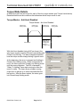
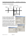
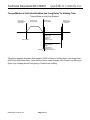
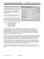
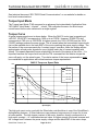
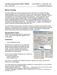
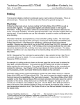
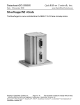
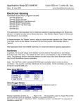
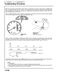
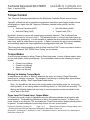
Technical Document:QCI-TD051 Date: 4 January 2008 QuickSilver Controls, Inc. www.QuickSilverControls.com Torque Control This Technical Document describes how the SilverLode Controller/Drivers control torque. Typically, a SilverLode servo generates torque based on position error (target position minus actual position), inputs from the Trajectory Generator (desired motion profile), and the commands: • Anti-Hunt Constants (AHC) • Anti-Hunt Mode (AHM) • Anti-Hunt Delay (AHD) • Torque Limits (TQL) By default, all motion occurs with torque being constantly adjusted. This is referred to as Closed Loop mode (or “the servo loop”). This allows the servo to use only as much torque as required for any given move. It is also possible to operate the servo without the benefits of the servo loop, which is called Open Loop mode. In Open Loop mode the servo has no feedback, and constantly applies the torque specified by a programmed limit (see TQL below). The closed loop torque equation as well as a flow chart the PVIA™ servo loop can be found in Technical Document “QCI-TD054 Servo Tuning” on our website. Torque Modes A servo may be operated in either Closed or Open loop mode. In each of these modes, there are two sub modes, Holding and Moving. The combination results in the following for torque modes: • Closed Loop Holding • Closed Loop Moving • Open Loop Holding • Open Loop Moving Moving Vs Holding Torque Mode In simple terms, the servo is “Moving” whenever the servo is in motion (Target Generator active) and is “Holding” otherwise. The transition from Moving to Holding takes a pre-defined time to allow for settling. See Torque Mode Details below. Note: It is possible for the motor to be moving while in the Holding mode (i.e. turning the shaft by hand), or not moving while in the Moving mode (i.e. if the shaft was jammed). The Moving and Holding modes are used only for control purposes and are not related to the actual state of the shaft. Open Loop Vs Closed Loop Torque Mode In Closed Loop mode, torque is calculated using the difference between target position and actual position. The greater the difference (or error), the greater the torque. In Open Loop mode, torque is set using the TQL command (see Torque Limits below) and the actual position is ignored. A simple example of closed loop control is a car’s cruise control. Property of QuickSilver Controls, Inc. Page 1 of 11 This document is subject to change without notice. QuickControl® and QCI® are Registered Trademarks of QuickSilver Controls, Inc. SilverLode™, SilverNugget™, SilverDust™, PVIA™, QuickSilver Controls™, and AntiHunt™ are trademarks of QuickSilver Controls, Inc.. Technical Document:QCI-TD051 QuickSilver Controls, Inc. Typically, the servo automatically switches between Open and Closed Loop modes based on the Anti-Hunt settings (see below), but the mode may be directly selected with the Go Open Loop (GOL) and Go Closed Loop (GCL) commands. See Command Reference for details on GOL and GCL. Anti-Hunt™ Anti-Hunt is enabled using the Anti-Hunt Constants (AHC) command and is used to automatically switch between Closed Loop mode and Open Loop mode, based on position error and torque level. Using the Anti-Hunt Mode (AHM) command, the servo can be set to enter Anti-Hunt only when holding a position, or it can be set to enter Anti-Hunt any time position error is low enough. When using open loop control to hold position, the controller applies a constant torque to the motor, ignoring small position errors. When using Open Loop mode during a move, the servo ignores small errors and applies torque to the motor based only on the motion profile from the Trajectory Generator. Anti-Hunt can make the servo operate more smoothly, but it also limits the final position accuracy. The following commands are important to Anti-Hunt operation. Typically, they are edited in the Initialization Wizard, but may be added to application programs: • Anti-Hunt Constants (AHC) • Anti-Hunt Delay (AHD) • Anti-Hunt Mode (AHM) • Torque Limits (TQL) • Error Limits (ERL) The AHC and AHD commands set the conditions under which the servo enters and exits AntiHunt, while the AHM command sets the type of Anti-Hunt operation the device uses. See Anti-Hunt Feature in User Manual for more details. QuickSilver Controls, Inc. Page 2 of 11 QuickSilver Controls, Inc. Technical Document:QCI-TD051 Torque Mode Details A different torque limit can be set for each of the four torque modes (see Torque Limits below). Described below are the conditions that determine which torque mode to use. Torque Modes - Anti-Hunt Disabled Torque Modes - Anti-Hunt Disabled Closed Loop Holding Mode Closed Loop Moving Mode Closed Loop Moving Mode Closed Loop Holding Mode Time ERL:Delay To Holding Time Change from Moving to Holding Torque Start of Move With Anti-Hunt disabled (using AHC as shown), the only torque modes used are Closed Loop Holding and Closed Loop Moving. The above diagram illustrates how the torque modes change during a typical move. At the beginning, the servo is stopped and holding in Closed Loop Holding mode. When commanded to move, the servo goes into Closed Loop Moving mode until the move completes. The ERL command’s “Delay To Holding” timer starts running to allow the motor to settle. The timer allows a higher moving torque limit to persist up to seven seconds after the last motion. After the timer expires, the servo goes into Closed Loop Holding mode. QuickSilver Controls, Inc. Page 3 of 11 Technical Document:QCI-TD051 QuickSilver Controls, Inc. Torque Modes w/ Anti-Hunt Enabled Torque Modes w/ Anti-Hunt Enabled Open Loop Holding Mode “Anti-Hunt” Closed Loop Moving Mode Closed Loop Moving Mode Closed Loop Holding Mode Open Loop Holding Mode “Anti-Hunt” Time ERL:Delay To Holding Time Change from Moving to Holding Torque Start of Move Settling AHD:Anti-Hunt Delay Change from Closed Loop to Open Loop Torque With Anti-Hunt enabled (using AHC and AHM as shown), the only torque modes used are Closed Loop Holding, Closed Loop Moving, and Open Loop Holding. The above diagram illustrates how the torque modes change during a typical move. At the beginning, the servo is stopped and holding in Open Loop Holding mode. When commanded to move, the servo goes into Closed Loop Moving mode until the move completes and ERL’s “Delay To Holding” timer expires at which time the servo goes into Closed Loop Holding mode. AHD’s “AntiHunt Delay” timer starts after the motor settles to within the “Closed to Open” limits specified by AHC. After the Anti-Hung Delay timer expires, the servo goes into Open Loop Holding mode. QuickSilver Controls, Inc. Page 4 of 11 Technical Document:QCI-TD051 QuickSilver Controls, Inc. Torque Modes w/ Anti-Hunt Enabled and Long Delay To Holding Time Torque Modes w/ Anti-Hunt Enabled Open Loop Holding Mode “Anti-Hunt” Closed Loop Moving Mode Closed Loop Moving Mode Open Loop Holding Mode “Anti-Hunt” Time ERL:Delay To Holding Time Change from Moving to Holding Torque Start of Move Settling AHD:Anti-Hunt Delay Change from Closed Loop to Open Loop Torque The above diagram illustrates what happens if ERL’s Delay to Holding timer is set longer than AHD’s Anti-Hunt Delay timer. Note that the torque mode changes from Closed Loop Moving to Open Loop Holding without ever going to Closed Loop Holding. QuickSilver Controls, Inc. Page 5 of 11 Technical Document:QCI-TD051 QuickSilver Controls, Inc. Torque Modes w/ Anti-Hunt Enabled and Position Error Without Move Torque Modes w/ Anti-Hunt Enabled Open Loop Holding Mode “Anti-Hunt” Closed Loop Holding Mode Closed Loop Holding Mode Open Loop Holding Mode “Anti-Hunt” Time Load Causes Motor Shaft to Move Settling AHD:Anti-Hunt Delay Change from Closed Loop to Open Loop Torque Command The above diagram illustrates what happens in Anti-Hunt when the load causes the motor shaft to move without a move command. As soon as the position error is greater than AHC’s “Open to Closed” parameter the torque mode changes to Closed Loop Holding. As long as the position error is less than AHC’s “Open to Closed” parameter, the Anti-Hunt Delay timer runs. Once the timer expires, the servo goes back to Open Loop Holding mode. Note, since there is no move, ERL’s Delay to Holding timer does not run. QuickSilver Controls, Inc. Page 6 of 11 Technical Document:QCI-TD051 QuickSilver Controls, Inc. Torque Limits Command (TQL) Torque limits have broad uses, including protecting machine parts at hard stops, web tensioning, allowing the shaft to free wheel, and reducing power consumption by the servo (and hence its temperature) when holding position. Torque limits are primarily changed using the Torque Limits (TQL) command. A servo may be operated in either closed or open loop mode. In each of these modes, the user can specify a holding and moving torque. The combination of these modes results in TQL’s four (4) torque limit parameters, one for each torque mode as discussed above. • Closed Loop Holding • Closed Loop Moving • Open Loop Holding • Open Loop Moving In a simple application, TQL is edited as part of the Initialization Wizard. However, it is perfectly acceptable to vary torque limits at any time by inserting a TQL anywhere in an application program. However, TQL is a class D command (See Command Reference for command classifications). This means TQL can only be executed from within a program or sent from a host while the servo is idle. For direct access to the torque limits, even during program execution, see Register Control below. 100% Torque is permitted for continuous duty assuming adequate heat sink and 25C ambient. Maximum torque above 100% is permitted, but at a reduced duty cycle and duration (typically 10% duty cycle depending on application). The primary difficulty with high torque and high duty cycle application is servo motor overheating. Short duty cycles (less than 10%) at Maximum torque can usually be used without restriction. The exact time depends entirely on the operating environment. If sufficient external cooling is provided, a SilverLode servo can operate at the Maximum setting indefinitely. A slight amount of air movement over the servo motor and controller can have a significant effect on temperature. To determine the actual torque that may be applied to the load, refer to the torque curve charts. The 100% torque applied to the load depends on the motor speed. See Torque Curve below. QuickSilver Controls, Inc. Page 7 of 11 Technical Document:QCI-TD051 QuickSilver Controls, Inc. Unit: Normal vs Native Typically, servos have a 100% torque level corresponding to a native value of 20,000 SilverLode Torque Units (STU) and a Maximum torque of 30,000 STU. The following I-Grade motors are the exceptions. In QuickControl, the TQL command automatically scales percentage values to STU (see Scaling in User Manual) depending on motor type. I-Grade Motors With Non-Standard 100% and Maximum Torque Limits (NOTE: All other I-Grade motors have 20,000 STU for 100% torque and 30000 STU for Maximum torque). NonSTU STU Standard @100% @Maximum Motors QCI-A34N-1 20,000 22,500 QCI-A34H-1 16,383 24,575 A STU does not directly correlate to a physical torque units (i.e. ounce-inches) because torque changes as speed changes. Therefore, QCI gives torque in “percentage” of available torque at current speed as defined by the published torque curves. See Torque Curve below. Closed Loop Holding Typically, a reduced torque level is desired as no motion is active; the lower level here can permit manual movement of an axis, or may reduce motor heating if a jam occurs. The purpose of the “Delay to Holding” is to permit the (typically) higher moving torque (if needed) at the end of a move so that any final vibrations may be settled before dropping to a lower torque level. Closed Loop Moving Typically a higher permissible torque level is desired for this mode to allow motion when commanded. Open Loop Holding This torque setting is frequently referred to as the Anti-Hunt™ torque (see Anti-Hunt in User Manual for details). The torque should normally only be set a margin above what is needed to hold the unit to minimize heating, however setting too low may cause the unit to cycle between open and closed loop in the Anti-Hunt mode due to not having sufficient torque in the open loop mode. This is an open loop mode, so the current required to generate the torque specified is always flowing through the windings. This current flow generates heat, increasing the temperature of the servo. If the servo is experiencing excessive heating while at rest, lowering this value can decrease the amount of heat generated. Excessive holding current contributes solely to the heating of the servo, so remember that less torque means less current, decreasing the operating temperature. In addition, torque is proportional to current, but heat is proportional to the square of current. Therefore, decreasing the torque setting by 30% will generally decrease the heat generated (at rest) by almost 50%; setting the torque to 30% reduces the heat to approximately 9% as compared to the 100% setting. QuickSilver Controls, Inc. Page 8 of 11 Technical Document:QCI-TD051 QuickSilver Controls, Inc. Open Loop Moving This torque is only used when a move is commanded and the AHM command is set to “when moving or stopped” as shown. In this Anti-Hunt mode, the servo uses Open Loop Moving mode during moves as long as the position error stays within the limits set in AHC. As this is an open loop mode, all the heating issues discussed above apply. Register Control The four torque limits set by TQL are stored in four 16-bit words in two data registers as shown (both registers are read/write capable): Reg 206 Reg 207 Upper 16 Bit Word Closed Loop Holding Open Loop Holding Lower 16 Bit Word Closed Loop Moving Open Loop Moving When the TQL command is executed, it simply writes its four parameters to registers 206 and 207. Use of the TQL command could be replaced with direct writes to these registers allowing the torque limits to be updated in real-time. The servo will begin using the new torque limit value within of one servo-cycle (120 usec) of the register update. Direct editing also allows individual limits to be adjusted, without changing any of the other three limits. Note that when writing to either register 206 or 207, the torque limits must be in SilverLode Torque Units (STU) (i.e. 20,000 STU = 100%). Registers 206 and 207 can be updated from any internal and external source. To change torque limits internally, use the CLC (or CLX) command to move the data. CLC has the ability to write to either the low word or high word of a register. Thus, an individual torque limit can be changed with CLC. The procedure for changing torque limits is to first copy, or write, the desired torque limit value into register 10, the accumulator. Be sure that the value is in native torque units. Copy this number from the Accumulator to the corresponding 16-bit half of torque limit register using CLC. In the CLC example below, CLC updates the closed loop moving torque limit, the low word of register 206. Updating the torque limits externally requires some type of host. Use the Write Register Immediate (WRI) command to write a value to a register and Read Register (RRG) to read the value of a register (see Command Reference). QuickSilver Controls, Inc. Page 9 of 11 Technical Document:QCI-TD051 QuickSilver Controls, Inc. See technical document “QCI-TD053 Serial Communications” on our website for details on host level communications. Torque Input Mode The Torque Input Mode (TIM) command is an advanced topic described in Application Note “QCI-AN047 Input Mode – Joystick”. In brief, TIM configures the servo for direct torque control based on the value contained in a single register. Torque Curve A typical torque-speed curve is shown below. When the 34HC-2 motor type is operating at +48 VDC, 30,000 STU corresponds to 1650 oz-in at 0 RPM. However, 30,000 STU also corresponds to 780 oz-in at 1000 RPM. At higher speeds, the 150% (30,000) and the 100% (20,000) settings produce the same torque. This is caused when the commanded torque levels can not be reached due to the back-EMF of the motor reaching the power supply voltage. The flat portion of the curve represents the “constant torque” operation, while the sloping section approximates a fixed power hyperbolic curve (slightly lower due to losses increasing with speed). This speed-dependant torque relationship is a result of the design of the motor. It is important because the torque limits set with the TQL command limit the relative torque the servo will apply, not the actual torque. The relative nature of the torque representation must be considered on applications with critical maximum torque requirements. 34HC-2 Torque vs. Speed Data 1800 48V MAX 1600 48V 100% 1400 36V 100% 24V 100% 1200 12V 100% 1000 Torque (in-oz) 600 400 200 0 0 500 1000 1500 2000 2500 Speed (rpm) The high pole count motor used with the SilverLode controller/driver is one of the QuickSilver’s distinguishing features. A SilverLode servo can produce a large amount of torque for its size at lower speeds. The high torque constant of the motor, however, directly corresponds to a high motor constant – i.e. volts/radian/second value. At higher speeds, the losses increase and the “voltage head” between the power supply voltage and the back EMF of the motor drops, QuickSilver Controls, Inc. Page 10 of 11 Technical Document:QCI-TD051 QuickSilver Controls, Inc. causing a reduction in torque at moderate to high speeds. For this reason, operating the device from higher voltages (up to +48 VDC) allows the system to attain higher speeds and greater output torque. Understanding torque-speed relationship is extremely important to properly using and sizing a SilverLode servo system. Reading Actual Torque The servo’s actual torque can be obtained from the low word of register 9 and is updated every servo cycle (120 uSec). In closed loop control, the torque value can be anything between plus or minus the torque limit setting. The torque value during open loop control will be the exact value in the TQL command. This is a read only data register. Chart vs Actual Torque The SilverLode servo it is not intended for use as a precision torque sensor. Attempting to set a servo to a precise torque (i.e. 200 oz-in) using TQL and the motor’s torque curve will get you within about 10%. The torque curves are de-rated from actual readings to insure all motors can meet the torque and efficiency changes a little from motor to motor. Speed, power supply drift, and temperature also affect the actual torque. The most linear torque range is from 20% to 80% of the torque rating (10% to 80% for SilverDust I-Grade controllers with an I-Grade motor). The nominal speed range lies on the torque plateau at the lower speed end of the torque curves. This is the area of the torque curve where the torque remains roughly constant as the speed increases. Temperature has a slight effect on the rotor magnetic strength, as well as motor winding resistance. Lower temperatures and torque/speed usage in the nominal regions improves torque accuracy. The power supply in use must also be taken into consideration. A supply in compliance with QCI specifications is highly recommended, and required to maintain the warranty. Further, variation in the voltage level, up to 10%, may vary the output torque similarly. These minimum power supply requirements are meant to ensure the servo can operate optimally. If all four of these requirements are met, torque variation is minimized. Note, The SilverDust I-Grade controllers, when mated to an I-Grade Motor enable the use of factory calibration values stored in the memory onboard the I-Grade motor. These calibration values significantly reduce the torque ripple of the system, and resulting velocity variations as compared to previous systems. QuickSilver Controls, Inc. Page 11 of 11