1
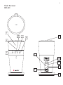
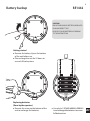
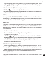
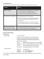
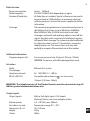
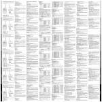
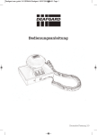
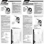
1 Flash Receiver BE1442/1443 Flash Receiver Model BE1442 input 7.5V 1500mA For indoor use only Made in the PRC N3583 US IPNMO01BERXT2 IC 66P3A-BERXT2 2 Flash Receiver BE1441 1 4 2 3 5 9 6 7 16 17 10 8 12 3 Appendix - Further information GB Settings No adjustments are required for normal use. The relevant descriptions are provided below, if you wish to change a setting for some reason. Radio key In order to use several Bellman Visit Systems close to one another without interference, different Radio Keys can be set on the different systems. All Bellman Visit System units are supplied from the factory tuned to the same Radio Key, channel 0. This means that all Radio Key Switches on the transmitters are set to the OFF position. A Bellman Visit transmitter is also required to alter the radio key on the Bellman Visit Flash Receiver. Proceed as follows to change the Radio Key: Set a Bellman Visit Transmitter to the desired Radio Key by altering its Radio Key Switch to the desired Radio Key. See the transmitter user manual for further information. Hold down the Test Button (9) on the Bellman Visit Flash Receiver until the green and yellow LEDs blink alternately. The Bellman Visit Flash Receiver will now be in programming mode for about 30 seconds. Press the Bellman Visit transmitter’s test button. The LEDs will now blink five times in quick succession to indicate a successful change of radio key. After changing the radio key, the Bellman Visit Flash Receiver will automatically return to normal mode. Please note: all Bellman Visit products within a system must be tuned to the same Radio Key in order to operate as a group. Signal pattern A Signal Pattern is the name for the way in which a receiver in the Bellman Visit System indicates activation. Changing the transmitters’ Signal Switch changes the Signal Pattern which the receivers display when the transmitter is activated. The following signal patterns are available for the Bellman Visit System: (Please note that the Flash Receiver does not emit any sound): 4 868/315MHz Europe, Asia Type LED pattern Sound Vibration Flash Green 1 Green is constantly lit 1 x ding dong, lowfrequency tone Separate Yes Green 2 Green blinks in sequences of two 2 x ding dong, lowfrequency tone Separate Yes Green 3 Green blinks in sequences of three 1 x ding dong, high-frequency tone Separate Yes Green 4 Green blinks constantly 2 x ding dong, high-frequency tone Separate Yes Yellow 1 Yellow is constantly lit 1 x ring, lowfrequency tone Short Yes Yellow 2 Yellow blinks in sequences of two 2 x ring ring, lowfrequency tone Short Yes Yellow 3 Yellow blinks in sequences of three 1 x ring, lowfrequency tone Short Yes Yellow 4 Yellow blinks constantly 2 x ring ring, highfrequency tone Short Yes IT Orange 1 Orange is constantly lit Baby Rapid Yes NL Orange 2 Orange blinks in sequences of two Baby Rapid Yes NO Orange 3 Orange blinks in sequences of three Baby Rapid Yes Orange 4 Orange blinks constantly Baby Rapid Yes VMA Red and Orange constantly blink alternately VMA constant Long Yes Red blinks constantly Fire alarm constant Fire alarm CZ DE DK ES FI FR GB GR HU PL PT SE SRB APP Long Yes 5 433MHz North America, Australia Type LED pattern Sound Vibration Flash Green 1 Green is constantly lit 1 x Ding dong, Bass tone Long Yes Green 2 Green is constantly lit 1 x Ring, Treble tone Short Yes Green 3 Green is constantly lit 1 x Ding dong, Bass tone Long Yes Yellow 1 Yellow is constantly lit 1 x Ding dong, Treble tone Long Yes Yellow 2 Yellow is constantly lit 1 x Ring, Bass tone Short Yes Yellow 3 Yellow is constantly lit 1 x Ding dong, Treble tone Long Yes Orange 1 Orange is constantly lit 2 x Ding dong, Bass tone Long Yes Orange 2 Orange is constantly lit 2 x Ring, Bass tone Short Yes Red 1 Red is constantly lit 2 x Ding dong, Treble tone Long Yes Red 2 Red is constantly lit 2 x Ring, Treble tone Short Yes Red 3 Red is constantly lit 2 x Ding dong, Treble tone Long Yes VMA Red and Orange constantly blink alternately VMA Constant Yes Fire alarm Red blinks constantly Fire Constant Yes 6 Battery backup Battery backup BE1442 BE1442 CZ CAUTION RISK OF EXPLOSION IF BATTERY IS REPLACED BY AN INCORRECT TYPE. DISPOSE OF USED BATTERIES ACCORDING TO THE INSTRUCTIONS. DE DK ES FI FR Getting started GB Remove the battery slip on the bottom of the unit before use. Please charge the unit for 24 hours to ensure full backup time. GR HU IT NL NO PL PT SE Replacing batteries (Done by the operator) Remove the screw on the bottom of the unit to exchange the batteries. SRB Use only 4x1.2VNiMH 600AAA/900AAA Lexel rechargeable batteries to ensure full backup time. APP 7 Bellman Visit Blitzempfänger BE1441/1442/1443 DE Vielen Dank, dass Sie sich für Produkte von Bellman & Symfon entschieden haben. Das Bellman Visit-System besteht aus verschiedenen Funksendern und Funkempfängern. Die Sender erkennen verschiedene Geräusche aus der Umgebung und senden ein Funksignal an die Empfänger. Die Empfänger empfangen dieses Signal und reagieren durch eine Leuchtanzeige, einen Ton und/oder Vibration. Der Sender entscheidet, welche Art von Leuchtanzeige, Ton oder Vibration ausgegeben werden soll, sodass der Benutzer die Ursache des Signals erkennen kann. Lesen Sie zunächst die Gebrauchsanweisung durch, bevor Sie mit der Montage des Systems beginnen. Siehe auch die Abbildung des Bellman Visit-Systems auf der Umschlaginnenseite. Erste Schritte Gerät auspacken, montieren und in Betrieb nehmen 1 Schließen Sie das Netzteil am Anschluss an. Drücken Sie die Prüftaste (9). Vom Bellman Visit Blitzempfänger werden dann Blitzlichtsignale ausgegeben, und falls ein Bellman Vibrationskissen, BE1270 (Zubehör), angeschlossen ist, vibriert dieses. 2 Zur Überprüfung des Funkempfangs ist ein Bellman Visit-Sender erforderlich. DrückenSie die Prüftaste eines Bellman Visit-Senders. Vom Bellman Visit Blitzempfänger werden Blitzlicht- sowie Leuchtsignale ausgegeben, und falls ein Bellman Vibrationskissen, BE1270 (Zubehör), angeschlossen ist, vibriert dieses. 3 Der Anschluss an eine analoge Telefonanschlussdose erfolgt über den Telefoneingang mit dem Telefonkabel BE9105 (Zubehör) sowie einem Modularstecker (Zubehör). Geht ein Anruf an die aktuelle Telefonnummer ein, gibt der Bellman Visit Blitzempfänger Blitzlichtsignale aus und schaltet die gelbe LED ein, und falls ein Bellman Vibrationskissen, BE1270 (Zubehör), angeschlossen ist, vibriert dieses. 4 Stellen Sie den Bellman Visit Blitzempfänger auf einer ebenen Fläche auf, oder montieren Sie ihn mit Hilfe der Bellman Wandkonsole, BE9075 (Zubehör), an der Wand. Platzieren Sie das Gerät möglichst an einem gut sichtbaren Ort. 8 Funktion Allgemeines Der Bellman Visit Blitzempfänger, BE1441/1442/1443, ist ein Empfänger im Bellman VisitSystem für die Innenanwendung, der die Aufmerksamkeit auf sich zieht, indem Blitzlichter und LEDAnzeigen, und sofern ein Bellman Vibrationskissen, BE1270 (Zubehör), angeschlossen ist, auch Vibrationssignale ausgegeben werden. CZ Die Aktivierung erfolgt über Funksignale von einem der Sender des Bellman Visit Systems oder über eine Direktverbindung mit einem analogen Telefonanschluss. DK Der Blitzkopf lässt sich in die gewünschte Richtung drehen. So können Sie das Blitzlicht z. B. gegen eine Wand richten, um nicht geblendet zu werden. ES Durch kurzes Drücken der Prüftaste (9) wird der BE1441/1442/1443 so aktiviert, dass er die letzte Signalausgabe wiederholt. Funkkanal Bei der Lieferung sind alle Bellman Visit-Einheiten auf denselben Funkkanal eingestellt. Sollten Sie einen Nachbar haben, der dasselbe System verwendet, können Sie den Funkkanal ändern, um eine Störung des Systems zu vermeiden. Der Funkkanal dieses Empfängers wird geändert, indem die Prüftaste (9) etwa fünf Sekunden lang gedrückt gehalten wird, bis die LEDs und abwechselnd blinken. Drücken Sie anschließend die Prüftaste des Senders, sodass die LEDs des Empfängers zur Bestätigung der Funkkanaländerung blinken. Alle Einheiten innerhalb eines Bellman Visit-Systems müssen auf denselben Funkkanal eingestellt sein, um zusammen funktionieren zu können. Einzelheiten entnehmen Sie der entsprechenden Gebrauchsanweisung. DE FI FR GB GR HU IT NL NO Anzeigen und Signale Im Bellman Visit-System wird im Allgemeinen durch die Sender festgelegt, welche Signale von den Empfängern ausgegeben werden. Weitere Informationen entnehmen Sie der Gebrauchsanweisung des jeweiligen Senders. Der Bellman Visit Blitzempfänger verfügt über eine Funktion, mit der man leicht überprüfen kann, welcher Alarm zuletzt ausgegeben wurde. Sie brauchen lediglich kurz auf die Prüftaste (9) zu drücken, um den letzten Alarm erneut auszugeben. PL PT SE SRB APP 9 Systemanzeigen Die LEDs , die angeben, von welchem Sender der Bellman Visit Blitzempfänger aktiviert wurde, haben in der Regel folgende Bedeutung: Die orange LED Die grüne LED Die gelbe LED Die rote LED bedeutet Babyüberwachung. bedeutet Türsender. bedeutet Telefonsender. bedeutet Feueralarm. Blinken die grüne und die gelbe LED abwechselnd, weist dies darauf hin, dass sich der Bellman Visit Blitzempfänger im Modus für die Wahl eines Funkkanals befindet. Der Blitzempfänger wartet dann auf ein Funksignal von einem Sender im Bellman Visit-System, das den Empfänger an denselben Funkkanal anpasst, auf den der Sender eingestellt ist. Blitzlicht Bei Aktivierung des Bellman Visit Blitzempfängers blitzt die Blitzleuchte (2) mit einem scharfen, weißen Licht. Der Blitzkopf lässt sich in die gewünschte Richtung drehen. So können Sie das Blitzlicht z. B. gegen eine Wand richten, um nicht geblendet zu werden. Vibration Der Bellman Visit Blitzempfänger kann ein Bellman Vibrationskissen BE1270 (Zubehör) betreiben, das am Anschluss angeschlossen wird. Das Vibrationskissen wird unter das Kopfkissen gelegt, sodass Sie geweckt werden, wenn der Bellman Visit Blitzempfänger aktiviert wird. Weitere Informationen zu den Vibrationsmustern finden Sie in der Gebrauchsanweisung des entsprechenden Bellman Visit-Senders. Stromversorgung Wenn die LED den. leuchtet, ist der Bellman Visit korrekt mit der Stromversorgung verbun- 10 Fehlersuche (Kurzübersicht) Maßnahme Es passiert nichts. Der Empfänger wird nicht aktiviert. Überprüfen, ob das Netzteil korrekt angeschlossen ist. Die LED muss grün leuchten. Überprüfen, ob auf der Steckdose Strom anliegt. Batterie der Sender überprüfen. CZ DE Symptom DE DK Sicherstellen, dass der Empfänger nicht zu weit von den Sendern entfernt ist. ES Überprüfen, ob der Empfänger auf den richtigen Funkkanal eingestellt ist. Siehe auch Funktion/Funkkanal. FI FR Die Empfänger im System geben Signale ohne Anlass. 1 2 3 4 5 6 7 Drehbarer Reflektor Blitz Orange LED Grüne LED Gelbe LED Rote LED Anschluss für Netzteil Funkkanal aller Einheiten des Systems auswechseln. Siehe auch Funktion/Funkkanal. 8 9 10 11 12 13 Telefoneingang für analoges Telefon Prüftaste Vibrationskissenausgang Kabelhalterung Tischständer Grüne LED Nähere Informationen zu diesem Produkt auf Englisch finden Sie im Appendix. Zweckbestimmung: Zulässige Betriebsbedingung: Reinigungshinweise: Wartungshinweis: Technische Daten: Hinweis zum Wiedereinsatz: GB GR HU IT NL NO Blitzlichtlampe zur optischen Signalisierung PL Für innen und außen in geschützter Lage. Verträgt kein Wasser oder Regen PT Nur mit trockenen/ leicht feuchtem Tuch abwischen Wartungsfrei (bei BE1442 können die Batterien ausgetauscht SE werden) 4 x AAA NiMH 600mAh Batterie (nur bei BE1442) SRB Das Produkt ist nicht für den Wiedereinsatz für einen andere Person vorgesehen APP 11 Advanced programming Advanced programming provides additional options for those who wish to make special modifications to the Bellman Visit Flash Receiver. The idea is that it should be possible to select a completely unique signal pattern which is linked to activation from a specific input on a special Bellman Visit transmitter. The function works regardless of the radio key settings on the units that are programmed. Please note that, for safety reasons, the function does not work with the BE1480 Bellman Visit Smoke Alarm. By using advanced programming of the Bellman Visit Flash Receiver, it can be adjusted so that its signal pattern corresponds exactly to what is required. In other words an entirely individual signal pattern can be programmed, such as displaying an orange permanently lit LED and a constant vibration. In order to adjust the setting, the Bellman Visit Transmitter to which the Bellman Visit Flash Receiver should be adapted must be available. The transmitter must also be connected so that it can be activated in the way in which it is intended to be used. Proceed as follows: 1 Hold down the Test Button (9) on the Bellman Visit Flash Receiver until the green and yellow LEDs blink alternately. The Bellman Visit Flash Receiver will now be in programming mode for about 30 seconds. 2 Hold down the Test Button (9) at the same time as the relevant Bellman Visit transmitter is activated in precisely the way in which it is intended to be used. Note that all inputs are individual. It is therefore not possible to use the Test Button on a Bellman Visit Telephone Transmitter whose telephone input will indicate the relevant pattern. 3 Scroll through the different LED options by a short press on the Test Button (9). Select the relevant indication by holding down the Test Button (9) until the LED goes out and starts to shine with a constant green light again. 4 Scroll through the different vibration options by a short press on the Test Button (9). Select the relevant indication by holding down the Test Button (9) until the LED goes out and starts to shine with a constant green light again. 5 The Bellman Visit Flash Receiver will now show the indication method programmed. End the display with a short press of the Test Button (9). 6 After a short while, the Bellman Visit Flash Receiver will automatically return to normal mode. This function is essential where a transmitter has to work in a special way with regard to a specific receiver. Resetting advanced programming It is quite easy to reset the Bellman Visit Flash Receiver if it needs to be reset after it has been programmed using advanced programming. 12 1 Hold down the Test Button (9) on the Bellman Visit Flash Receiver until the green and yellow LEDs blink alternately. The Bellman Visit Flash Receiver will now be in programming mode for about 30 seconds. 2 Press the Test Button (9) three times in quick succession. 3 All LEDs remain constantly on for a few seconds. CZ 4 All the advanced programming has now been deleted and the Bellman Visit Flash Receiver will automatically return to normal mode. DE Testing DK It is easy to test the BE1441/1442/1443 Bellman Visit Flash Receiver. If the Flash Receiver does not work as described below, you can check further below under Appendix/Further information/Troubleshooting/Troubleshooting guide. ES How to test A transmitter in the Bellman Visit System which is set to the same Radio Key as the Bellman Flash Receiver is required to test the flashing light and vibration, if the BE1270 Bellman Bedshaker (accessory) is connected, and the radio reception on the BE1441/1442/1443 Bellman Visit Flash Receiver. Press the transmitter test button. The Bellman Visit Flash Receiver will give the following indications: o Flashing with the flash light (2). o The LEDs which the transmitter has been set to indicate with or which have been programmed into the Flash Receiver with Advanced Programming will be switched on. o If the BE1270 Bellman Bed-shaker (accessory) is connected, it will vibrate as the transmitter has been set to indicate or in the way the Flash Receiver has been pro grammed with Advanced Programming. FI FR GB GR HU IT NL NO To test the analogue telephone input: PL Connect the Bellman Visit Flash Receiver to an analogue telephone socket via the Telephone Input . Use the BE9105 Telephone Flex (accessory) and an adapter plug (accessory). PT Ring the telephone number. The Bellman Visit Flash Receiver will then start flashing, the yellow LED will light up and, if a BE1270 Bellman Bed-shaker (accessory) is connected, it will vibrate. A short press on the Test Button (9) activates BE1441/1442/1443 so that it repeats its last indication. SE SRB APP 13 Troubleshooting You can carry out a number of checks yourself before sending a product for repair. Problem Solution Nothing happens. The receiver is not activated. The receiver signals when no transmitter is activated. Check that the power supply unit is connected correctly. The LED should light up green. Check that there is current in the wall socket. Check the battery in the transmitters. Check that the receiver is not placed too far away from the transmitters by moving it closer to the transmitters. Check that the receiver is set to the correct radio key. For further information see Function/Radio key. Change the Radio Key on all units in the system. For further information see Function/Radio key. Technical information Power supply Mains power: Battery back-up 7.5 V DC / 1500 mA. This product is also designed for IT power distribution system with phase to phase voltage of up to 230V. The socket-outlet shall be installed near the equipment and shall be easily accessible. Europe: BE9092 (Something High Electric P12-075150EU) Great Britain: BE9217 (Something High Electric P12-075150UK) US/CAN: Something High Electric P12-075150US Australia/NZ: Something High Electric P12-075150AS for BE1441: not applicable for BE1442: 4x1.2V Lexel 600/900mAh for BE1443: 4x1.2V Lexel 900mAh Please dispose used batteries at municipal collecting points or dispense them to local stores free of charge. 14 Radio function Power consumption: Radio frequency: Number of Radio Keys: Coverage: Active: 1500 mA 315/433.92/868.3 MHz depending on region 64 Radio Keys as standard. Special software can be used to increase these to 256 Radio Keys in increments of 64 per software purchase. Contact the nearest supplier for further information. The normal coverage between a transmitter and receiver in the Bellman Visit System is up to 200 metres (868MHz)/ 80m (433MHz)/ 50m (315MHz) with clear line of sight. Coverage is reduced if walls and large objects screen off the signals. Any thick walls constructed of reinforced concrete will greatly affect coverage. The system may also be affected by radio transmitters such as TV transmitters, computers, mobile phones, etc. This means that a unit may work perfectly in one part of the room but not at all in another. For service personal only (Output: 3.3V/max. 150mA) CAUTION: Do not use, unit will be damaged when used. DK ES FI FR GR HU Activation Radio: Via analogue telephone network: 26 - 120 V RMS, 15 - 100 Hz. BE1441/BE1442: Via mobile phone detector Bellman Visit system IT : see accessories (Output: 3.3V/max 150mA) WARNING: The telephone port of the Flasher Receiver must be connected using 26 AWG or greater telecommunications wire. Output signals Output signals DE GB Additional information Programming pin (16): CZ NL NO PL PT Vibrator power Built-in flash light signal >10 Candela Warning! Flashes can cause epileptic attacks. 2.0 – 4.0 VDC (max. 500mA) For indoor use only Dimensions Ø x H: Weight: Colour: Temperature range 0°C – 40°C 70 x 140 mm 320 g White SE SRB APP 15 Optional accessories (sold seperately) Wall Mount Bracket BE9075 Bellman Bed-shaker BE1270 Telephone Flex BE9105 Mobile Detector BE9250 Adapter plug for the appropriate country IT Activation For use in all EU countries Correct use and disposal of batteries. Replace only with the same or equivalent type recommended by the manufacturer. Please dispose of old, Radio: Bellman Visit system defective batteries in an environmentally friendly manner in accordance with the relevant Via analogue legislation. Dispose used batteries at municipal R&TTE 1999/5/EC, LVD 1973/23/EC, EMC collecting points or dispense them toHz. local stores telephone network: 26 - 120 V RMS, 15 - 100 1989/336/EC and MDD 1993/42/EEC. Dimensions Ø x H: Weight: Colour: Warning! Flashes can cause epileptic attacks. Symfon Asia Ltd. 2.0Bellman – 4.0&VDC 1115-16 , Main Tower, GD Int’l Bldg. 339 Huanshi Dong Rd Guangzhou, China, 510095 Phone +86 20 8318 2950 E-mail [email protected] 70 x 140 mm 320 g White TM and © 2013 Bellman & Symfon AB. All rights reserved. All product designs are patented. Accessories Wall Mount Bracket BE1441_047MAN003.indb 76 BE9075 Bellman Bed-shaker BE1270 Telephone Flex BE9105 Adapter plug for the appropriate country Hereby, Bellman & Symfon, declares that this wrist receiver and charger is in compliance with the essential requirements and other relevant provisions of directives: R&TTE 1999/5/EC, LVD 1973/23/EC, EMC 1989/336/EC and MDD 1993/42/EEC. Bellman & Symfon Europe AB Södra Långebergsgatan 30 421 32 Västra Frölunda Sweden Phone +46 31 68 28 20 E-mail [email protected] For use in all EU countries Correct use and disposal of batteries. Replace only with the same or equivalent type recommended by the manufacturer. Please dispose of old, defective batteries in an environmentally friendly manner in accordance with the relevant legislation. Dispose used batteries at municipal collecting points or dispense them to local stores free of charge. Bellman & Symfon Asia Ltd. 1115-16 , Main Tower, GD Int’l Bldg. 339 Huanshi Dong Rd Guangzhou, China, 510095 Phone +86 20 8318 2950 E-mail [email protected] TM and © 2013 Bellman & Symfon AB. All rights reserved. All product designs are patented. NO PL CZ CZPT DE DESE DK DKSRB ES ES bellman.com APP FI FI FR FR 2013/7/25 10:57:32 GB GB GR GR HU HU IT IT NL NL Zusätzliche Information Nur Innen verwenden. Wartungsfrei. Nur mit einem leicht feuchten Tuch reinigen. free of charge. Output signals Bellman & Symfon Europe AB Vibrator power Södra Långebergsgatan 30 421 32 Västra Frölunda Additional information Sweden Phone +46indoor 31 68 28 20 For use only E-mail [email protected] Contact us For a complete Declaration of Conformity please contact [email protected] or call +46 31 68 28 20 BE1441_047MAN003 76 NL Hereby, Bellman & Symfon, declares that this wrist receiver and charger is in compliance with the essential requirements and other relevant provisions of directives: Contact us For a complete Declaration of Conformity please contact [email protected] or call +46 31 68 28 20 Zusätzliche Information Nur Innen verwenden. Wartungsfrei. Nur mit einem leicht feuchten Tuch reinigen. NO NO PL PL PTPT SESE SRB SRB bellman.com APP APP