1
NS1000
CLASSROOM MATERIAL
(TRAINER)
Introduction
This material refers to the KX-NS1000 PBX system, and details the basic information that should be
covered in a classroom session (1 day)
The Session comprises of the following sections;
NS1000 – Installation & Initialisation
NS1000 – WebMC
NS1000 – Terminal Registration
NS1000 – User Profiles
NS1000 – DSP Resources
NS1000 – Networking
NS1000 – Upgrade & Backup
NS1000 - Maintenance
From following this course element, participants will be gain an understanding of how to install,
initialize and maintain the NS1000 system.
Further information about feature implementation and specifications, may be found in the
associated Installation Manual, Feature Guide and User Manual.
Section - 1
INSTALLATION AND
INITIALIZATION
Introduction
This material refers to the KX-NS1000 PBX system, and details the basic steps necessary to install
and initialize the unit.
The Module comprises of the following sections;
NS1000 – Installation
NS1000 – System Initialization
From following this course element, participants will be gain an understanding of how to install
and initialize the NS1000 ready for first use.
Further information about feature implementation and specifications, may be found in the
associated Installation Manual, Feature Guide and User Manual.
Contents
Chapter 1 Installation
1.1 Unpacking
1.2 Component Location
1.3 Option Installation
1.4 Rack Mounting
1.5 Desk Mounting
1.6 Wall Mounting
1.7 Earth / Surge Protector connection
1.8 Connecting Power
1.9 External Connections
Chapter 2 System Initialization
2.1 System Initialization
2.2 Web Console Preparation
2.3 Web Console Connection
2.4 1st Login
2.5 Easy Setup
Chapter 3 Slave Initial Configuration
3.1 Slave Initial Configuration
3.2 Slave Registration
Chapter 4 System Outline
4.1 UPS Connection and setting
Chapter 1
INSTALLATION
NOTE
IMPORTANT:
Before installing the NS1000 system, refer to the Installation Manual. The Installation Manual
contains specific information regarding the safe installation of the unit and also details specific
installation and wiring precautions.
The information contained in this presentation is intended to supplement the NS1000 Installation
Manual by providing an overview of the installation and initialization process and in no way replaces
the published Installation Manual.
Where any information contained herein appears unclear or incomplete, the information contained
in the published NS1000 Installation Manual shall take precedence.
1.1 Unpacking (1)
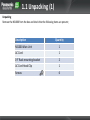
Unpacking
Remove the NS1000 from the box and check that the following items are present;
Description
Quantity
NS1000 Main Unit
1
AC Cord
1
19” Rack-mounting bracket
2
AC Cord Hook Clip
1
Screws
6
1.2 Component Location (1)
Component location (External)
The main ports, jacks and LEDs etc are shown below;
Front Side
LED indicators
System mode SW
Back Side
AC cord clamp
AC IN
AC SW
MOH/EPG ports
USB port
GROUND
DPH Port (Option)
Legacy Slot (Option)
IP ports
Serial port
FAN
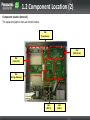
1.2 Component Location (2)
Component location (Internal)
The expansion/option slots are shown below;
Slot
(Doorphone)
Slot
(FAX Server)
Slot
(Trunk/SLT)
Slot
(Storage Memory)
Slot
(DSP 2)
Slot
(DSP 1)
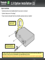
1.3 Option Installation (1)
Option Installation
• Optional cards can be installed when the top cover is removed.
• Option Cards are not “Hot-Swap”
• Power must be removed from the unit before optional cards are installed
1. Ensure the Power
Switch is ‘OFF’
2. Remove 3 screws from
the rear of the top cover.
NB: Where possible, Option cards should be installed before installing and powering-on the unit for the first time. When this is
not possible, the system must first be ‘SHUTDOWN’ using the Web Maintenance Console.
Removing the power without shutting down the unit may damage the systems file-structure and render the system inoperable.
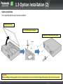
1.3 Option Installation (2)
Option Installation
The required options can now be installed.
3. Remove the cover
4. Install the required options
5. Replace the top cover and screws.
CAUTION:
When installing or removing option cards, do not put pressure on the main board. Damage to the option and main board may result.
1.4 Rack Mounting
Rack Mounting the NS1000
The NS1000 can be rack-mounted using the supplied brackets and screws.
1. Mount the brackets onto the NS1000.
2. Bolt the NS1000 into the rack using the hardware supplied by the rack manufacturer.
Size = 2U
Dimensions:
430mm×88mm×340mm
Weight : Under 4.5kg
(Fully Mounted)
NB: Ensure that there is sufficient ventilation around the system and that the rack temperature limit is not exceeded.
(Refer to the Installation manual for further details)
1.5 Desk Mounting
Desk Mounting the NS1000
The NS1000 can be installed on a flat surface.
• The unit MUST be placed flat on it’s base (Not on it’s back, sides or upside-down etc)
• The units FAN opening MUST be clear
• A 10cm gap around the sides and 20cm over the top of the unit MUST be maintained.
• DO NOT place flammable (wood etc) objects behind the unit (Refer to the Installation Manual for more
details)
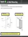
1.6 Wall Mounting
Wall Mounting the NS1000
The NS1000 can be installed onto a suitable wall using the optional Wall Mounting kit.
(Refer to the Installation Manual for further details)
1.
Install the screws
(with suitable wall anchors etc)
2.
Mount the unit to the wall
(using the Wall Mounting Kit)
NB: The unit must be installed with the arrows on the Wall Mounting brackets pointing “UP”.
In any other orientation, the unit will not be secured correctly to the wall and may fall.
1.7 Earth / Surge Protector connection
Frame Ground (Earth) and Surge Protection
(Refer to the Installation Manual!)
Frame Ground
Surge Protection
WARNING
• Proper connection to earth is very important to reduce the risk to the user of electrocution or to protect the PBX from the effects of
external noise or lightning strike.
• The earth wire of the AC cable has an effect against external noise and lightning strikes, but it may not be enough to protect the PBX
and to ensure electromagnetic compatibility. A permanent connection between earth and the earth terminal of the PBX must be
made.
• To protect the system from electrical surges, it is strongly recommend to connect the system to a surge protector that meets the
following specifications:
• Surge arrestor type: 3-electrode arrestor
• DC spark-over voltage: 230 V
• Maximum peak current: at least 10 kA
Many countries/areas have regulations requiring surge protection.
Be sure to comply with all applicable laws, regulations, and guidelines.
1.8 Connecting Power
Connecting the AC Cord
Using the AC Cord supplied with the unit, connect it to the PBX and secure with the supplied AC Cord Clip.
Connect the other end of the AC
Cord to the UPS System.
AC Cord Clip
UPS System:
A UPS should be connected to the PBX to provide temporary in the event of a power failure.
When using the recommended UPS (APC RS Series with USB interface), the PBX can shutdown automatically by sending a warning signal to
the PBX through the USB port.
By shutting down correctly, data loss or serious damage to the PBX caused by a sudden power cut can be prevented.
When power is restored, turn off the PBX using the power switch first, and then turn the PBX back on before starting the PBX.
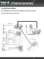
1.9 External connections
Connecting Peripherals and Options
Once the NS1000 has been mounted, various peripherals and options can be connected.
(Refer to the Installation Manual for further details)
Chapter 2
SYSTEM INITIALISATION
2.1 System Initialisation
After installing the option cards, initialize the system (factory default settings)
1. Ensure the power switch is OFF.
2. Slide the System Mode Switch to the “SYSTEM INITIALIZE” position.
System Mode
Switch
3. Turn the power switch ON. (STATUS and MASTER LED will flash AMBER), the STATUS LED will then
flash GREEN.
4. Slide the System Mode Switch back to the “NORMAL” position. (When the STATUS LED is flashing.)
Indicators
BATT
STATUS ALARM MASTER
STATUS = RED (No DHCP)
STATUS = GREEN (DHCP)
MASTER = Flashing AMBER
(Master/Slave not assigned)
5. When successfully executed, the STATUS indicator will
stop flashing and stay lit. (RED or GREEN)
Refer to Appendix for LED Sequence Detail.
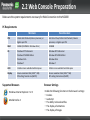
2.2 Web Console Preparation
Below are the system requirements necessary for Web Connection to the NS1000
PC Requirements
Minimum
Recommended
CPU
1.0GHz Intel Pentium/Celeron processor, or
higher spec CPU
Intel Core 2 Duo/3.2GHz Intel Pentium/ Celeron
processor, or higher spec CPU
RAM
256MB (1024MB for Windows Vista)
2048MB
OS
Windows XP Professional
Windows XP HOME Edition
Windows Vista
Windows 7
Windows XP Professional
Windows XP HOME Edition
Windows Vista
Windows 7
HDD
1.5GB or more available hard disk space
10GB or more available hard disk space
Display
Screen resolution: XGA (1024 * 768)
DPI setting: Normal size (96 DPI)
Screen resolution: XGA (1024 * 768)
DPI setting: Normal size (96 DPI)
Supported Browsers
Windows Internet Explorer 7 or 8
Mozilla Firefox 4
Browser Settings
Enable the following functions in the browser's settings:
• Cookies
• JavaScript
• The ability to download files
• The display of animations
• The display of images
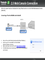
2.3 Web Console Connection
When the system has been initialized, the Setup Wizard can be run via the Web Maintenance Console
(Web-MC).
Connecting a PC to the NS1000 via the Web-MC
DHCP Client
DHCP Server
1.
2.
3.
4.
Set your PC as a DHCP Client (Automatically Obtain IP Address.)
Connect your PC to the MNT Port of the NS1000
(Default IP Address 223.0.0.1)
Open you Browser and enter the URL http://223.0.0.1/WebMC
The Web Maintenance Console login screen will then be displayed in
your browser.
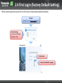
2.4 First Login (Factory Default Setting)
When connecting to the system for the first time, the Easy Setup Wizard will launch.
1st Login
(The PBX is in the factory default state)
Default Settings:
Username: INSTALLER
Password: 1234
2. Click Install
1. Select the Web-MC Language
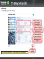
2.5 Easy Setup (1)
Location Setting
1. Set the unit status (Master/Slave), Suffix and Area
Set the unit
as Master or
Slave.
Set the unit Suffix Code
(UK, NE, CE, GR etc) and
your required country.
The Suffix Code can be
found on the units
Nameplate and box
Click ‘Next’ to
continue.
• If the Unit is to be configured as a Slave unit of a One-Look System on a Remote Site (Different Network than the Master), then set
the PBX Type as ‘Slave’ and enter the Master PBX IP Address in the Location Setting. (Master units in a One-Look system or StandAlone units must be configured as a ‘Master’.
• It is important to select the correct Suffix/Country settings so that the correct default tones, emergency dial and other country
specific data are set automatically.
2.5 Easy Setup (2)
PBX Setting
2. Give the system an appropriate name and set the Time Zone
Use a name which easily
identifies the unit.
Select the Time Zone.
The Local date and time are
obtained automatically from
your PC. Check that the PC
date/time is correct.
Click ‘Next’ to
continue.
2.5 Easy Setup (3)
LAN Setting
3. Enter the required LAN Settings
By default, the PBX uses
a static IP Address
(Recommended)
By default, no DNS server
addresses are set. Configure
them as required.
By default, the DSP Cards
use DHCP to obtain an IPAddress, however static
addresses can also be
assigned.
Note: If you are Not using DHCP then you Must assign a DSP IP Address Manually.
Click ‘Next’ to
continue.
2.5 Easy Setup (4)
LAN Setting
4. Enter the IP Terminal Registration Mode setting and select if ‘One-Look’ Trial should start.
There are three terminal registration Modes;
Manual:
Suitable for all supported IP Terminals and network configurations.
Registration information is set manually in the Terminal and PBX.
(This is the recommended setting when a range of IP/SIP Terminals will
be used with the system.)
Full Automatic:
Suitable for UT/NT Terminals connected to the same network as the PBX.
All settings, including Extension Number are registered automatically.
NB: DHCP Server Required
Extension Number Input:
If ACTIVE is selected,
then the 60-day OneLook Trial will start. If
NON-ACTIVE is selected,
it is possible to Activate
the Trial at a later date.
Suitable for NT Terminals connected to the same network as the PBX. All
network and registration settings are registered automatically. The
Extension number is configured manually via the Terminal.
NB: DHCP Server Required
Click ‘Next’ to
continue.
Note:
1. Non-UT Series SIP Terminals must be registered manually.
2. By default, the UT-Series SIP Extension password is automatically set to ‘1234’
2.5 Easy Setup (5)
SNTP (Simple Network Time Protocol) / Daylight Saving Setting
5. The source used for automatic time adjustment and the Daylight Saving mode is set here.
This is useful to keep the time displayed on the terminals and SMDR records etc accurate.
Automatic Time Adjustment can
be made using ISDN/Analogue
Trunks (ISDN/FSK) or via a
suitable SNTP server.
For countries using ‘Daylight
Saving’ - automatic adjustment
can be set here.
Click ‘Next’ to
continue.
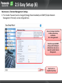
2.5 Easy Setup (6)
Maintenance / Remote Management Settings
6. The Installer Password can be changed (Strongly Recommended) and SNMP (Simple Network
Management Protocol) can be configured here.
Be sure to change the default
Installer password up
installation.
Use a strong password.
Check the required SNMP
settings with the Network
Administrator and enter as
required to enable Remote
Management.
Click ‘Finish’ to
complete Easy Setup.
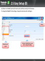
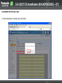
2.5 Easy Setup (7)
If the systems LAN settings were changed during Easy Setup, you will be prompted to restart the PBX
so that the changes can take effect. Be sure to login with the new password etc
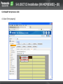
2nd Login
(Easy Setup has been completed)
Login with the new password.
Detailed system configuration
can now be made.
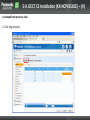
2.5 Easy Setup (8)
By Default, the WebMC portal will remain active (without activity) for 60 minutes.
To change the WebMC Portal settings, change the time here after 2nd login :-
Settings
Network Service
5. HTTP
To change the WebMC Auto Logout
timer – change this setting.
Chapter 3
SLAVE INITIAL CONFIGURATION
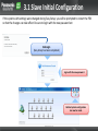
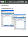
3.1 Slave Initial Configuration
Location Setting
1. Set the unit status as Slave.
2. Enter the IP Address of the Master System.
Set the unit as Slave.
Enter the IP Address of
the Master Unit.
Default IP Address:
192.168.0.101
Click ‘Next’ to
continue.
3.1 Slave Initial Configuration
LAN Setting
3. Enter the required LAN Settings. Change the IP Address to a different number within the same range
Change the IP Address
to a different number
within the same range
Click ‘Next’ to
continue.
Note: If you are Not using DHCP then you Must assign a DSP IP Address Manually.
3.1 Slave Initial Configuration
LAN Setting
Note: Once the LAN settings has changed, the system will need to reboot.
The bellow pop-up will be displayed. Click OK to reboot system.
3.1 Slave Initial Configuration
Registration Setting
4. Enter the IP Terminal Registration Mode as Manual. Full automatic can be used but is not covered
in this document. Manual entry reduces the number of Empty Extension numbers in CA.
Activate the 60-day OneLook Trial if required.
Click ‘Next’ to
continue.
Note:
1. Non-UT Series SIP Terminals must be registered manually.
2. By default, the UT-Series SIP Extension password is automatically set to ‘1234’
3.1 Slave Initial Configuration
SNTP (Simple Network Time Protocol) / Daylight Saving Setting
5. The source used for automatic time adjustment and the Daylight Saving mode is set here.
This is useful to keep the time displayed on the terminals and SMDR records etc accurate.
Automatic Time
Adjustment can be
made using
ISDN/Analogue Trunks
(ISDN/FSK) or via a
suitable SNTP server.
For countries using ‘Daylight
Saving’ - automatic adjustment
can be set here.
Click ‘Next’ to
continue.
3.1 Slave Initial Configuration
Maintenance / Remote Management Settings
6. The Installer Password can be changed if required. Even if you want to keep as default (1234) you
must re-enter it here before continuing.
Even if you want to keep the
default password you must reenter it before continuing.
Click ‘Finish’
to complete.
3.1 Slave Initial Configuration
If the systems LAN settings were changed during Easy Setup, you will be prompted to restart the PBX
so that the changes can take effect. Be sure to login with the new password etc
2nd Login
(Easy Setup has been completed)
Login with the new password.
Detailed system configuration
can now be made.
3.2 Slave Registration
Once the both systems have been initially configured, the Slave system needs to be added to the
Master system network. Log into the Master system. You will be presented with the bellow screen.
Click on the Add Site Button.
Add Site
Follow the prompts to add the desired Slave site.
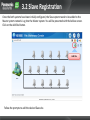
3.2 Slave Registration
Once the Slave system has been added to the network, the Slave system needs to be registered to
the Master system. Log into the Master system. You will be presented with the bellow screen. Click
on the List button.
List View
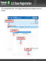
3.2 Slave Registration
Click on the Registration button. From the popup, select the Slave system displayed in the list and
click Next.
Click on Registration
Select Slave Unit
Select move button
Click Next
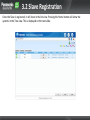
3.2 Slave Registration
Once the Slave is registered, it will show in the list view. Pressing the Home button will show the
systems in the Tree view. This is displayed on the next slide.
3.2 Slave Registration
Once the Slave has been registered, it will show on the Home screen (In-Service).
Chapter 4
UPS CONNECTION
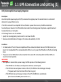
4.1 UPS Connection and setting (1)
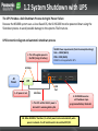
UPS (Uninterruptible Power Supply) Integration
Description
An uninterruptible power supply unit (UPS) is a device that supplies power for several minutes to a connected
device when a power failure occurs.
If the PBX is connected to a compatible UPS via USB when a power failure occurs, the PBX can determine
how much power remains in the UPS and shut down when the remaining power drops below a specified amount
to prevent data loss or corruption.
The following features are also available:
• Specify the remaining battery level at which to shut down the PBX.
• Receive e-mail notifications of changes to the status and availability of a UPS.
Conditions
• For details about UPS units that are compatible with the automatic shutdown feature of this PBX, consult your dealer. If an
incompatible UPS is connected and the UPS runs out of power, the PBX will turn off without shutting down.
• The power cord and USB cable must be connected to the same UPS. Connecting them to different UPS’s can result in incorrect
operation.
IMPORTANT
• When power is restored after a power outage, the PBX operates in the following manner:
– If the PBX did not shut down, normal operation continues uninterrupted.
– If the PBX shut down and power remains in the UPS, the PBX must be started again manually.
(The power switch must be turned off and then on again.)
– If the PBX shut down and no power remains in the UPS, the PBX starts automatically.
(This is because the PBX's power switch is on.)
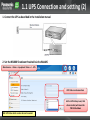
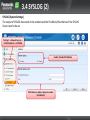
4.1 UPS Connection and setting (2)
1. Connect the UPS as described in the Installation manual
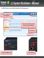
2. Set the NS1000 Shutdown threshold via the WebMC
Maintenance -> Status -> Equipment Status -> 1. UPS
UPS Status can be seen here
Set the UPS Battery Level, that
when reached, will cause the
PBX to Shutdown
NB: UPS Status alerts can also be sent via email.
SYSTEM INITIALIZATION COMPLETE
Section - 2
WEB MAINTENANCE
CONSOLE
Introduction
Web Maintenance Console (Web MC)
All features and settings of the PBX can be set through system programming with the Web
Maintenance Console.
The following explains the installation procedure, basic structure and operation of the WebMC.
Contents
Chapter 1 Overview
1-1. Web Maintenance Console
1-2. Operating Modes
1-3. User’s Account
Chapter 2 Connections
2-1. System Requirements
2-2. Available Connections
2-3. Accessing Web MC
2-4. Logging into Web MC
Chapter 3 WebMC – Tour
3-1. Screen Descriptions
3-2. Button Descriptions
3-3. SLOT View
Chapter 4 Appendix
Static NAT Setting Example
Chapter 1
OVERVIEW
1-1. Web Maintenance Console - Overview
There is only one Programming Tool for KX-NS1000.
The NS1000 WebMC is a web-based application which allows you to manage the PBX system easily.
• KX-NS1000 does NOT support Unified PC Maintenance Console (UPCMC) for KX-NCP/TDE/TDA.
• KX-NS1000 does NOT support the system programming using proprietary telephones.
1-2. Operating Modes
There are two programming modes; Interactive Mode & Batch Mode
• Interactive Mode (Allows real-time access and configuration of the PBX system.)
•Direct Connection (http)
•Via LAN (http)
•Via VPN (http)
•Via Internet (https)
• Off-Line Mode (Configuration is done Off-Line and applied to the PBX at a later date.)
Available 2012
•Direct Connection (http)
•Via LAN (http)
•Via VPN (http)
•Via Internet (https)
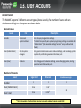
1-3. User Accounts
Account Levels
The WebMC supports 3 different account types (Access Levels). The number of users who can
simultaneously login to the system are shown below.
Account Levels
Level
For
Description
Installer
Dealers and
system installers
For all system programming settings.
“Installer” can specify which system programming settings are available for
“Administrator” (the accessible settings for “User” are pre-defined and
fixed).
User (Administrator)
On-site system
managers
For general maintenance of users and user settings, such as backing up the
system data, confirming extension information, etc.
User (User)
End users
For changing user’s extension settings, such as changing profiles, storing
personal speed dial numbers, etc.
Number of Accounts
Level
Single Unit
One-look
Simultaneous Login
1
1
1
User (Administrator)
0-16
0-16*1
User (User)
0-16
0-1512*1
Installer
*1
The total number of administrator and user accounts combined cannot exceed 1512.
32
Chapter 2
CONNECTIONS
2-1. System Requirements
System Requirements
Requirements
Descriptions
- Windows XP
- Windows Vista Business
- Windows 7 Professional
Both 32bit and 64bit version is available.
HDD
100MB of available hard disk space
Minimum Requirements
Display
-Screen resolution: XGA (1024 * 768)
-DPI setting: Normal size (96 DPI)
Recommended Settings
Browsers
- Windows Internet Explorer 8 or 9
- Mozilla Firefox version 5.0 or later
Make sure you are using the latest version of the
above Web browser software. For details, refer to
the Web browser’s documentation.
Browser
Settings
- Cookies
- Java Script
- The ability to download files
- The display of animations
- The display of images
These functions must be enabled in the Web
browser’s settings to use Web Maintenance
Console.
For details, refer to your Web browser’s
documentation.
OS
TBD
2-2. Available Connections (1/3)
In order to program or manage the PBX, you need to connect your PC to the PBX.
Several connection methods are provided, and here you can see the outline of the direct connection.
1. Direct Connection (MNT Port)
Set the PC as a
DHCP client.
The MNT port is set as a DHCP server.
- Ethernet cable with an RJ45 connector
- Maximum Distance: 100 m
If the PC has “Gigabit Ethernet interface”, an Ethernet “crossover cable may be needed.
It depends on the specification of the PC.
2-2. Available Connections (2/3)
It is also possible to manage the PBX via a LAN or VPN connection.
2. LAN/VPN Connection (LAN Port)
• Via LAN
• Via VPN
Switch
Switch
- 10BASE-T/100BASE-TX: CAT 5 or higher
- 1000BASE-T: CAT 5e or higher
- Maximum length: 100 m
- Auto Negotiation: ON
- If using VLAN:
The switch must be IEEE 802.1Q compliant, and set the port to “Untagged”.
2-2. Available Connections (3/3)
Using the WebMC and suitable network routing, it is possible to access the PBX system via the Internet.
Ensure that appropriate security measures are in-place before attempting this. (Firewall etc)
3. Connection via Internet
Switch
Specify static NAT (port forwarding)
settings to the router.
- 10BASE-T/100BASE-TX: CAT 5 or higher
- 1000BASE-T: CAT 5e or higher
- Maximum length: 100 m
- Auto Negotiation: ON
- If using VLAN:
The switch must be IEEE 802.1Q compliant,
and set the port to “Untagged”.
The WAN port on the KX-NS1000 is not supported with ver. 1.0.
2-3. Accessing the Web MC
There are different addresses depending on Connection Types:
1. When Connecting via MNT Port
http://kx-ns1000. (or http://223.0.0.1)
Be sure to include the period (.) at the end as shown.
“223.0.0.1”: the default IP address of the MNT port = Fixed
2. When Connecting via LAN or VPN
http://192.168.0.101/WebMC
“192.168.0.101”: the default IP address of the LAN port = Variable
3. When Connecting via Internet (SSL Connection)
https://xxx.xxx.xxx.xxx/yyy
“xxx.xxx.xxx.xxx” will be an IP address, and “yyy” will be a port numbers that can be accessed
from the internet, for example the IP address and port number of a router.
Port forwarding settings must specify the IP address and the port number of the network
router ("xxx.xxx.xxx.xxx:yyy") to transfer the packets to the PBX in the LAN, so that the
packets sent to the global IP address and specified port of the router will be transferred
to the IP address and specified
The URL is case-sensitive. Enter the uppercase and lowercase letters exactly as shown above.
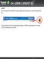
2-4. LOGIN / LOGOUT (1)
LOGIN
After establishing a connection to Web Maintenance Console, the login window is displayed, and a
login name and password must be entered.
Login Restrictions
• Up to 33 users may log in at one time to Web Maintenance Console. However, only 1 user may
change PBX system settings at a time. (1 Installer / 32 Admin/Users)
If a User is making changes, and the Installer logs in, the Installer may override the user’s ability to
make changes so that programming can be performed.
Users that are logged in to Web Maintenance Console, but do not have the ability to make changes,
may only view menus and setting items they would normally be able to edit.
• If a user fails to log in three times (wrong password), the failure is recorded in the error log of the
PBX and the user cannot log in again for 5min.
2-4. LOGIN / LOGOUT (2)
LOGOUT
Be sure to log out from the Web MC using the Logout button, otherwise any unsaved changes will be
lost.
Clicking this button will save any programming changes to the PBX’s Storage Memory Card and log
you out of Web Maintenance Console.
Chapter 3
WEBMC - TOUR
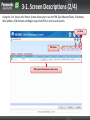
3-1. Screen Descriptions (1/4)
Upon LOGIN, you are presented with the ‘Home’ Screen
Home Screen Icon
PBX Slaves
Loads the Home screen.
Displays the Maintenance screen.
Displays the Setup screen.
Saves the data.
Opens the on-line help.
PBX Maser
Displays the Web MC version info.
Saves the data and logs you out.
Adds slave units.
Displays the Home screen
in icon view.
Displays the Home screen
in list view.
3-1. Screen Descriptions (2/4)
Using the ‘List’ view in the ‘Home’ Screen allows you to see the PBX Type (Master/Slave), IP-Address,
MAC address, S/W Version and Region type of all PBXs in a One-Look system.
List View
PBX Status
PBX System Information is shown here.
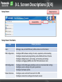
3-1. Screen Descriptions (3/4)
Setup Screen
Setup Screen Icon
Connected Site
Setup Screen Tree Items
Item
Primary Functions
Users
• Manage, view, and add PBX user profiles and account information
PBX Configuration
• Configure PBX hardware settings for cards, equipment, and networking
• Configure network-wide programming such as BGM and Class of Service
• Configure dialing features, call routing, and incoming call settings
• Configure call logging (SMDR) and other PBX maintenance items
UM Configuration
• Configure Unified Messaging mailboxes and voice mail subscriber settings
• Configure service settings and system parameters
• Configure hardware options
Network Services
• Configure server and client features for the PBX
• Configure connections settings and network security
3-1. Screen Descriptions (4/4)
Maintenance Screen
Maintenance Screen Icon
Maintenance Screen Tree Items
Item
Primary Functions
Status
• Check the status of the PBX’s system hardware
• Check the status of PBX equipment (PSs, CSs, UPS, etc.)
• Check the status of extensions used by the Unified Messaging system
System Control
• Download and update PBX software files
• Manage music on hold (MOH) data
• Reset or shutdown the system
Tool
• Backup system data to a USB memory device
• View a list of PBX extensions
• Import and export PBX settings and user information
• Backup or restore Unified Messaging data
Utility
• Perform tests for PBX cards and network connections
• Transfer files between the PBX and a connected PC
• View reports, error logs, event logs, and program update logs
• Monitor and trace PBX communications and protocols
• Manage activation keys and license information
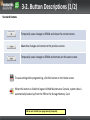
3-2. Button Descriptions (1/2)
Standard Buttons
Temporarily saves changes to DRAM and closes the current screen.
Abandons changes and returns to the previous screen.
Temporarily saves changes to DRAM and remains on the same screen.
To save setting while programming, click this button on the Home screen.
When this button is clicked to logout of Web Maintenance Console, system data is
automatically backed up from the PBX to the Storage Memory Card.
NB: Be sure to SAVE your programming frequently
3-2. Button Descriptions (2/2)
Each Setting screen has a number of helpful icons available. The available icons will differ, depending
on the screen.
Standard Icons
Copies Data Fields
Deletes the selected row
Edits the selected row
Adds new entry
Remove filter
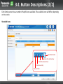
3-3. Slot View
In the ‘Settings’ View, the ‘SLOT’ view shows what Physical and Virtual cards are installed. May other
system properties or features can also be viewed.
‘Settings’ -> PBX Configuration ->
1. Slot
Select ‘Physical’ or ‘Virtual’ Slot View
Status Buttons
Installed ‘Physical’ Cards
Chapter 4
APPENDIX
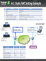
A-1 Static NAT Setting Example
Setting Items
Descriptions
1
Interface
WAN-side interface
2
Protocol
TCP or UDP
3
Receiving Port No. (WAN side)
Outside network port number (1~65535)
4
IP Address of Transfer Destination (LAN Side)
The destination IP address to which the packets are transferred.
5
Port No. of Transfer Destination (LAN Side)
The port number of (1~65535)
PBX 1
IP Address: 192.168.0.2
Protocol: TCP
Web MC Port No.: 443
PBX 1: https://133.149.172.28:8080
PBX 2: https://133.149.172.28:8081
Static NAPT
Dynamic NAPT
Local IP Address: 192.168.0.1
Global IP Address: 133.149.172.28
Local IP Address: 10.75.60.1
Global IP Address: 133.125.149.44
PBX 2
IP Address: 10.75.60.2
I/F: a
IP Address: 192.168.0.3
Protocol: TCP
Web MC Port No.: 443
Internet
I/F: b
Setting Items
For PBX 1
For PBX 2
Interface
a
b
Protocol
TCP
TCP
Receiving Port No. (WAN Side)
8080
8081
IP Address of Transfer Destination
192.168.0.2
192.168.0.3
Port No. of Transfer Destination
443
443
No particular settings
WEBMC COMPLETE
Section - 3
TERMINAL
REGISTRATION
Introduction
The NS1000 supports 3 methods of IP terminal registration.
1. Full Automatic Mode
When an IP terminal is connected to the network, the IP terminal will automatically discover the
main unit and an unallocated extension number will automatically assigned to the IP Terminal.
2. Extension Input Mode
When an IP terminal is connected to the network, the IP terminal will automatically discover the
main unit and the user will be asked to input an extension number.
3. Manual Mode
Same operation as TDE/NCP.
Supported Modes – by terminal type.
1. Full Automatic Mode
2. Extension Input Mode
3. Manual Mode
UT series
Yes
No
Yes
NT3xx / NT265
Yes
Yes
Yes
NT700
No
No
Yes
General SIP Phone
No
No
Yes*
(*) Only input the Password
NB: DHCP Server is required for Full/Extension Input Modes
Contents
Chapter 1 UT/NT Series Registration
1-0. NS1000 – DCHP Server Setting
1-1. Full Automatic Mode – Overview
1-2. PBX System Configuration
Chapter 2 NT Series Registration
2-1. Extension Number Mode – Overview
2-2. PBX System Configuration
Chapter 3 UT Series Registration
3-1. Manual Registration Mode – Overview
3-2. Manual Registration (UT)
3-3. PBX Configuration (UT)
3-4. Registration Confirmation (UT)
Chapter 4 NT Series Registration
4-1. Manual Registration (NT)
4-2. PBX Configuration (NT)
4-3. Registration Confirmation (NT)
Contents
Chapter 5 DECT CS Installation
5-0. DECT CS Installation
Chapter 6 Registration – Other Terminals
6-0. Registration
6-1. De-registration
Chapter 1
UT/NT SERIES REGISTRATION
FULL AUTOMATIC MODE
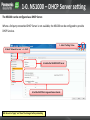
1-0. NS1000 – DHCP Server setting
The NS1000 can be configured as a DHCP Server.
Where a 3rd party networked DHCP Server is not available, the NS1000 can be configured to provide
DHCP Services.
1. Select ‘Settings’ View
2. Select ‘Network Service’ -> 1. DHCP
Thank you !
The END
3. Enable the NS1000 DHCP Server
4. Set the DHCP Pool range and lease interval.
NB: Be sure to ‘Apply’ and ‘Save’ the changes before proceeding.
1.1 ‘Full Automatic’ Registration Mode
Full Automatic Mode – Overview
When UT/NT PTs are connected to the NS1000 on the same network – Full Automatic Registration of
the Terminals is possible. No manual setting of the PTs or PBX is required.
Requirements;
1. DHCP Server (NS1000 or External DHCP Server)
2. V-IPEXT32 or V-UTEXT32 Card is installed in the NS1000
3. Sufficient IP-PT A/Ks are installed.
UT/NT
Series PT
LAN
Switching HUB
LAN
Port
DHCP
Server
1.2 PBX System Configuration (1)
Confirm the IP Terminal Registration Mode
1. Login to the Web-MC
3. Select 1.1 ‘Slot’ -> ‘Site Property’ -> ‘Main’
4. Confirm the system is in “Full Automatic” Mode.
2. Select ‘Setup’
1.2 PBX System Configuration (2)
Install a Virtual Extension card (V-IPEXT32 or V-UTEXT32) - 1
5. Select 1.1 ‘Slot’ -> ‘Virtual’
6. Install the V-Ext Card
1.2 PBX System Configuration (3)
Install a Virtual Extension card (V-IPEXT32 or V-UTEXT32) - 2
7. Click ‘OK’ to install the V-Ext card.
8. Select ‘Port Property’.
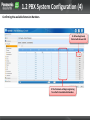
1.2 PBX System Configuration (4)
Confirming the available Extension Numbers.
10. When Registered,
the Ext will show as INS
9. The Terminals will begin registering
from the first available Ext Number.
Chapter 2
NT SERIES REGISTRATION
EXTENSION NUMBER MODE
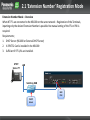
2.1 ‘Extension Number’ Registration Mode
Extension Number Mode – Overview
When NT PTs are connected to the NS1000 on the same network – Registration of the Terminals,
inputting only the desired Extension Number is possible. No manual setting of the PTs or PBX is
required.
Requirements;
1. DHCP Server (NS1000 or External DHCP Server)
2. V-IPEXT32 Card is installed in the NS1000
3. Sufficient IP-PT A/Ks are installed.
UT/NT
Series PT
LAN
Switching HUB
LAN
Port
DHCP
Server
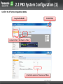
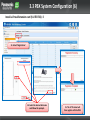
2.2 PBX System Configuration (1)
Confirm the IP Terminal Registration Mode
1. Login to the Web-MC
2. Select ‘Setup’
3. Select 1.1 ‘Slot’ -> ‘Site Property’ -> ‘Main’
4. Confirm the system is in “Extension Input” Mode.
2.2 PBX System Configuration (2)
Install a Virtual Extension card (V-IPEXT32) - 1
5. Select 1.1 ‘Slot’ -> ‘Virtual’
6. Install the V-IPEXT32.
2.2 PBX System Configuration (3)
Install a Virtual Extension card (V-IPEXT32) - 2
7. Click ‘OK’ to install the V-IPEX32 card.
8. Select ‘Port Property’.
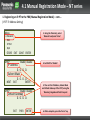
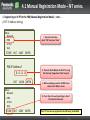
2.2 PBX System Configuration (4)
Connect the NT Series IP-PT to the network (which includes DHCP Server) and input the desired Ext
number via the IP-PT Keypad when prompted.
Note:
a.) If extension number is set in V-IPEXT32, but has no PT registration, the IP-PT will
automatically register to the first available Port/ Ext number (you will not be prompted
to enter an Ext number from the PT.)
b.) If you enter a number which is already used, you will hear an error tone.
9. Enter the desired Ext
number and press ENTER
Ext 101
c.) If you do not input an Ext number within 60s, then the IP-PT will register to an available
port (No Ext Number). The desired Ext Number can then be set via the WebMC.
11. When Registered, the Ext will show as
INS, MAC address and s/w version etc
10. The Terminal will register to the first available
port once the desired Ext number is input.
EXIT CLEAR ENTER
(NT3xx Display)
Chapter 3
UT SERIES REGISTRATION
‘MANUAL’ MODE
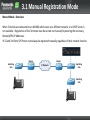
3.1 Manual Registration Mode
Manual Mode - Overview
When Terminals are connected to an NS1000 which exists on a different network, or a DHCP Server is
not available – Registration of the Terminals must be carried out manually by entering the necessary
Network/PBX IP Addresses.
IP-CS and 3rd Party SIP Phones must always be registered manually, regardless of their network location.
Router
Switching
Hub
Router
IP Network
Switching
Hub
Switching
Hub
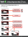
3.2 Manual Registration Mode – UT series
1. Registering an UT-PT to the PBX (Manual Registration Mode)
When registering a UT without a local DHCP server OR when registering the UT from a remote
location etc, you will need to enter the IP Address of the UT AND the IP Address of the PBX into the
UT manually (Manual Registration Mode).
1. Connect the UT to the network and
apply power (PoE or AC Adaptor etc)
Now starting…
Setup
2. When the UT powers on, press the
‘SETUP’ soft-key below the LCD display
3.2 Manual Registration Mode – UT series
1. Registering an IP-PT to the PBX (Manual Registration Mode) – cont….
(UT-PT IP Address Setting)
Information Display
Network Settings
Back
3. Using the ‘Navi-Key’, select
‘Network Settings’ and press ‘Enter’.
Enter
NAVI-KEY
4. Select ‘Network’
Network
VLAN
Back
Enter
DHCP
STATIC
Back
5. Select ‘STATIC’ for the IP Address mode
Enter
6. Then set the IP-Address, Subnet Mask
and Default Gateway of the IP-PT, using the
‘Navi-key’, Keypad and ‘Enter’ keys etc
IP Address
192.168.0.153
Back
Enter
Subnet mask
255.255.255.0
Back
ENTER
Enter
Default Gateway
192.168.0.1
Back
Enter
3.2 Manual Registration Mode – UT series.
1. Registering an IP-PT to the PBX (Manual Registration Mode) – cont….
(UT-PT IP Address Setting)
Information Display
Network Settings
Back
Enter
7. The Network address and MAC information
can be confirmed by navigating back to the
‘Information Display’ screen
The PBX IP-Address (location) will be set automatically during the registration process.
The registration process (UT <-> PBX) must be carried out within the same Broadcast
domain.
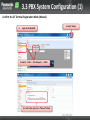
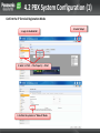
3.3 PBX System Configuration (1)
Confirm the UT Terminal Registration Mode (Manual)
1.
Login to the Web-MC
3. Select 1.1 ‘Slot’ -> ‘Site Property’ -> ‘Main’
4. Confirm the system is in “Manual” Mode.
2. Select ‘Setup’
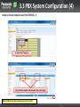
3.3 PBX System Configuration (2)
Install a Virtual Extension card (V-UTEXT32) - 1
5. Select 1.1 ‘Slot’ -> ‘Virtual’
6. Install the V-UTEXT32 Card and set the number of users.
3.3 PBX System Configuration (3)
Install a Virtual Extension card (V-UTEXT32) - 2
7. Click ‘OK’ to install the V-Ext card.
8. Select ‘Out Of Service’.
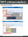
3.3 PBX System Configuration (4)
Install a Virtual Extension card (V-UTEXT32) - 3
9. Select ‘Port Property’.
10. Set the Ext number and Password, then click ‘Apply’
NB: By Default, the extension Password is set to ‘1234’
3.3 PBX System Configuration (5)
Install a Virtual Extension card (V-UTEXT32) - 4
11. Set the port ‘In Service’.
12. Select ‘IP-Phone’ Registration -> ‘SIP-MLT’
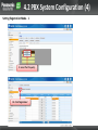
3.3 PBX System Configuration (6)
Install a Virtual Extension card (V-UTEXT32) - 5
13. Select ‘Registration’.
14. Select the desired Extension
and follow the prompts.
15. The UT Terminal will
then register with the PBX.
3.4 Registration Confirmation (UT)
Confirm the registration
10 OCT. 12:09PM MON
103
Setting
Call Log
11. After the UT-PT has re-booted and the WebMC Registration
process has been completed, the UT-PT will be in-service.
Menu
Further Extension configuration can now be made via the WebMC, using the Extension Number of the IP-PT.
From the V-UTEXT32 Port Properties screen, the UT registration status, Password, MAC, IP-Address and firmware version can be seen.
Chapter 4
NT SERIES REGISTRATION
‘MANUAL’ MODE
4.1 Manual Registration Mode – NT
series
1. Registering an IP-PT to the PBX (Manual Registration Mode)
When registering an IP-PT without a local DHCP server OR when registering an IP-PT from a remote
location etc, you will need to enter the IP Address of the IP-PT AND the IP Address of the PBX into
the IP-PT manually (Manual Registration Mode).
1. Connect the IP-PT to the network and
apply power (PoE or AC Adaptor etc)
Searching…
SETUP
2. When the IP-PT powers on, press the
‘SETUP’ soft-key below the LCD display
4.1 Manual Registration Mode – NT series
1. Registering an IP-PT to the PBX (Manual Registration Mode) – cont….
(IP-PT IP Address Setting)
3. Using the ‘Navi-Key’, select
‘Network’ and press ‘Enter’.
Menu
-> Network
PBX
IP Port
QoS
STORE EXIT CONT ENTER
DHCP
Enable Disable
IP Address
0. 0. 0. 0.
Subnet Mask
0. 0. 0. 0.
NEXT
EXIT
DHCP
ENTER
Enable Disable
Default Gateway
0. 0. 0. 0.
EXIT
PREV
ENTER
4. Set DHCP to ‘Disable’
5. Then set the IP-Address, Subnet Mask
and Default Gateway of the IP-PT, using the
‘Navi-key’, Keypad and ‘Enter’ keys etc
6. When complete, press the ‘Enter’ key.
4.1 Manual Registration Mode – NT series.
1. Registering an IP-PT to the PBX (Manual Registration Mode) – cont….
(IP-PT IP Address Setting)
Menu
Network
-> PBX
IP Port
QoS
7. Using the ‘Navi-Key’,
select ‘PBX’ and press ‘Enter’.
STORE EXIT CONT ENTER
PBX IP Address ?
0. 0. 0. 0.
EXIT CLEAR ENTER
Menu
Network
-> PBX
IP Port
QoS
STORE EXIT CONT ENTER
8. Then set the IP-Address of the IP-PT, using
the ‘Navi-key’, Keypad and ‘Enter’ keys etc
9. When complete, press the ‘ENTER’ key to
return to the ‘Menu’ screen.
10. Press ‘Store’ to save the settings in the IPPT and re-boot the unit.
The IP-PT can then be registered to the PBX using the WebMC.
4.2 PBX System Configuration (1)
Confirm the IP Terminal Registration Mode
1. Login to the Web-MC
3. Select 1.1 ‘Slot’ -> ‘Site Property’ -> ‘Main’
4. Confirm the system is in “Manual” Mode.
2. Select ‘Setup’
4.2 PBX System Configuration (2)
Install a Virtual Extension card (V-IPEXT32) - 1
5. Select 1.1 ‘Slot’ -> ‘Virtual’
6. Install the V-IPEXT32 Card.
4.2 PBX System Configuration (3)
Install a Virtual Extension card (V-IPEXT32) - 2
7. Click ‘OK’ to install the V-IPEX32 card.
4.2 PBX System Configuration (4)
Setting Registration Mode - 1
9. Select ‘Port Property’.
10. Click ‘Registration’.
4.2 PBX System Configuration (5)
Setting Registration Mode - 2
11. Select the desired Extension
number and follow the prompts.
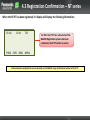
4.3 Registration Confirmation – NT series
When the NT-PT has been registered, it’s display will display the following information;
19 JUL.
10:14
TUE
12. After the IP-PT has re-booted and the
WebMC Registration process has been
completed, the IP-PT will be in-service.
PROG INFO RING MENU
Further Extension configuration can now be made via the WebMC, using the Extension Number of the IP-PT.
Chapter 5
DECT CS INSTALLATION
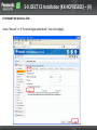
5-0. DECT CS Installation (KX-NCP0158CE) – (1)
To assign a static IP Address to the KX-NCP0158CE IP-CS, the Panasonic UPCMC Tool is required. It is
not possible to set a static IP Address on the IP-CS via the NS1000 WebMC.
Step 1. Assign the IP-CS IP address, subnet, PBX IP address, . etc,
UPCMC Tool is required. (Available from your NSC)
1
2
Select IP Terminal
4
3
Press next
Change DIP SW 7 to ON and
Power off/on the IP-CS.
5
Assign 192.168.2.xxx as PC
IP address and press next.
Assign IP-CS data like IP address, PBX IP address, etc.,
and press next. After that, Power off/on the IP-CS.
NB: By default, the KX-NCP0158CE is set to DHCP. It is only necessary to set a static IP Address if there is
no available DHCP Server or if the IP-CS is to be placed on a Network different than then PBX.
5-0. DECT CS Installation (KX-NCP0158CE) – (2)
Continued from previous slide
6
5-0. DECT CS Installation (KX-NCP0158CE) – (3)
Step 2 - Registering IP-CSs to the PBX
Click [Setup] select [PBX Configuration] – [1.Configration] – [1.Slot]
[IP Phone Registration] – [Option] or [Site Property] – [Main]
5-0. DECT CS Installation (KX-NCP0158CE) – (4)
Continued from previous slide
Select “Manual” in “IP Terminal Registration Mode”, then click [Apply].
5-0. DECT CS Installation (KX-NCP0158CE) – (5)
Continued from previous slide
1. Click [Setup] select [PBX Configuration] – [1.Configuration] – [1.Slot] select [Virtual]
5-0. DECT CS Installation (KX-NCP0158CE) – (6)
Continued from previous slide
2. Select [V-IPCS4]
5-0. DECT CS Installation (KX-NCP0158CE) – (7)
Continued from Previous slide
3. Select [Number of cards], then click [OK]
Cancel
5-0. DECT CS Installation (KX-NCP0158CE) – (8)
Continued from previous slide
4. Select [Port property]
5-0. DECT CS Installation (KX-NCP0158CE) – (9)
Continued from previous slide
5. Click [Registration]
5-0. DECT CS Installation (KX-NCP0158CE) – (10)
Continued from previous slide
6. Select [IP-CS Index], then click [Next]
5-0. DECT CS Installation (KX-NCP0158CE) – (11)
Continued from previous slide
7. After Registration completed, then click [Close]
Chapter 6
REGISTRATION – OTHER TERMINALS
6-1. Registration – Other Terminals
Other Terminals such as:
• KX-NT700 (Conferencing Unit)
• TCA/WT Series DECT Terminals
• 3rd Party SIP Telephones
Must all be registered using ‘Manual’ Registration mode.
Notes:
For KX-NT700 and 3rd Party SIP Telephones – ensure a V-SIPEXT32 (inc A/Ks) is installed.
DECT Handsets (TCA/WT) are registered in the same manner as TDE/NCP PBX systems.
6-2. De-Registration (1)
Registered Terminals can be de-registered from the system via the Virtual Cards ‘Port Properties’
1. Select the De-Registration mode.
a. Use ‘De-Registration’ mode when the Terminal
is connected to the system and powered on.
b. Use ‘Forced De-registration when the terminal is
not connected to the system or is faulty.
6-2. De-Registration (2)
After selecting the de-registration mode, select the desired extension and follow the prompts.
When the de-registration process is complete,
the display of the terminal will indicate that it is
not registered. (Fault, Poor Connection etc)
TERMINAL REGISTRATION COMPLETE
SECTION - 4
NS1000
USER / ADMIN / INSTALLER
PROFILES
Contents
Chapter 1
UT/NT Series Registration
1-1. Overview
1-2 . Default Profile (INSTALLER)
1-3. Creating a Profile
1-4. Profile Types (User)
1-5. Profile Types (User + Rec Control)
1-6. Profile Types (Administrator)
1-7. Profile Types (Installer)
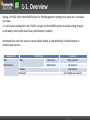
1-1. Overview
Setting a ‘Profile’ within the NS1000 allows for PBX Management settings to be made on a individualuser level.
i.e. Each person having their own ‘Profile’ can login to the NS1000 system and make setting changes
as allowed by their profile level (User, Administrator, Installer)
Information for each User account can be added, edited, or and deleted by an Administrator or
Installer level account.
Available Via
Web
Maintenance
Profile Type
Users
Installer
Password
User Level
Admin Level
Capacity
1512 accounts
32 accounts
One account
4 to 16 digits per account
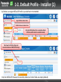
1-2. Default Profile - Installer (1)
By Default, an single INSTALLER Profile is pre-defined in the WebMC
Login Profile is shown here.
Profile list view is shown here.
Only the INSTALLER profile is created by default.
All other profiles must be created manually.
Tabs show the Profile settings and
associated Extension FWD/DND settings
Only the INSTALLER Password is stored by default, all other fields are empty (default)
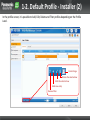
1-2. Default Profile - Installer (2)
In the profile screen, it is possible to Add, Edit, Delete and Filter profiles depending on the Profile
Level.
Create Range
Deletes the selected row
Edits the selected row
Adds new entry
Remove filter
1-2. Default Profile - Installer (3)
From the Installer Level profile (Maintenance Screen), it is possible to select which screens the
Administrator Profiles can see
Maintenance -> Tool ->
8. Screen Customise
Specify which menu screens, tools and
utilities can be accessed in the User
(Administrator) account level.
NB: By Default, an Administrator cannot see any Profile screen – this must be selected here to
enable an Admin to view their own Profile etc.
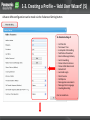
1-3. Creating a Profile – ‘Add User Wizard’ (1)
By clicking the ‘Add User’ option, the Add User Wizard starts
1. Click ‘Add User’
2. Wizard start and prompts for User Information.
3. Enter the Users details,
location and WebMC
Language preferences*.
*Available Languages
depends on your PBX
model type.
4. Select ‘User’ or
‘Administrator’ Profile type.
5. Click ‘OK’
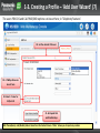
1-3. Creating a Profile – ‘Add User Wizard’ (2)
Next step is to enter the users Contact information, this is necessary for CA
6. Wizard prompts for Contact Information.
7. Select an existing Ext
number and set a PIN
8. Enter DDI, FAX, Phone and
Email data
9. Click ‘OK’
NB: Extension numbers must be pre-existing. It is not possible to input a ‘New’ Ext number.
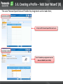
1-3. Creating a Profile – ‘Add User Wizard’ (3)
Next step is to configure the users Mailbox
10. Wizard prompts for UM data.
11. Select the UM group,
Mbx number and desired
UM COS.
12. Mbx prompts / greetings, Passwords and Advanced
Mbx settings can be made via the appropriate key.
NB: Mbx numbers must not pre-existing.
Mbxs are automatically created by this step.
1-3. Creating a Profile – ‘Add User Wizard’ (4)
Individual Mbx prompts can be set via the ‘Prompt’ Registration button;
14. Click ‘Play/Record
15. Record the Message from a PT,
or input a recording from your PC
13. Owners Name, Personal Greetings and Caller
information can be recorded here.
NB: File format is: CCITT A-law, 64kbps, 8kHz, 8bit, Mono (After conversion from .wav)
1-3. Creating a Profile – ‘Add User Wizard’ (5)
Advance Mbx configuration can be made via the ‘Advanced Setting button
16. Detailed settings of
•
•
•
•
•
•
•
•
•
•
•
•
•
•
•
Call Transfer
No Answer Time
Incomplete Call Handling
Notification Parameters
External Message Delivery
Auto Forwarding
Personal Custom Service
Personal Distribution Lists
Remote Call
Automatic Login
Direct Service
FAX Options
Message Announcements
Message Client Language
Greeting Recording
Can be made here.
1-3. Creating a Profile – ‘Add User Wizard’ (6)
It is possible to set if the user will receive and email for missed call (Email Notification).
17. Enable or Disable Email Notification.
NB: Email Activation Key is required per User.
1-3. Creating a Profile – ‘Add User Wizard’ (7)
The users PBX COS and Call-FWD/DND options can be set here; in ‘Telephony Features’
18. Set the desired COS Level.
19. C-FWD preferences
are set here
20. Select if same for
Int/Ext call
21. Set Speed Dial
and Flexible Keys
NB: Phone(Home) and (Mobile) data is taken from the Contact Screen. ‘Other’ allows you to input any number.
1-3. Creating a Profile – ‘Add User Wizard’ (8)
The users Personal Speed Dial and Flexible Key Assignment can be made here;
22. Up to 100 Personal Speed Dials can be set
23. UT Flexible Key assignment must be
done via WebMC (User Profile)
1-3. Creating a Profile – ‘Add User Wizard’ (9)
Last step is to create the users Login Account (ID and Password).
This will allow the user to Login via the WebMC and change their details / settings etc in future.
24. Enter the Appropriate ID and Password
(Strong Passwords are better)
Change Language:
English
25. INSTALLER can change the
Web MC language from the
Login Account.
26. Click ‘OK’ to Finish
NB: When Logging In, the user will only see the screens / data that they are allowed to change based on their profile
(User / Administrator / Installer etc)
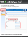
1-4. Profile Types – ‘User’
A User profile only allows changes to limited settings;
Many setting options are not displayed or cannot be changed by the user.
System Settings
cannot be seen.
Many Items cannot be changed.
For details of what can be changed via a User profile, refer to the Appendix;
1-5. Profile Types – ‘User’ + ‘REC Control’
A User profile with Rec Control only allows changes to limited settings, however the user can access
the necessary recordings.
Many other setting options are not displayed or cannot be changed by the user.
Two-Way Recording folder
can be seen.
Other System Settings are
not shown.
For details of what can be changed via a User + 2-Way Rec profile, refer to the PC-Programming Guide
1-6. Profile Types – ‘Administrator’
An Administrator profile allows changes to limited system settings;
An Administrator is able to manage User profiles.
System Log data can also be obtained
via the Maintenance Screen
Basic System Settings can be
changed to enable local
administration and configuration
For details of what can be changed via an Administrator profile, refer to the PC-Programming Guide
1-7. Profile Types – ‘Installer’
An Installer profile allows System wide configuration and Maintenance;
An Installer is able to manage Administrator and User profiles.
Complete Maintenance tools and System
Master/Slave structure can be seen
All System Settings can be changed
to enable complete system
configuration
For details of what can be changed via an Installer profile, refer to the PC-Programming Guide
USER PROFILES COMPLETE
Section - 5
DSP RESOURCES
Contents
1.1
1.2
1.3
1.4
Overview
DSP Resource Capacity
DSP Resource Usage
DSP Usage – Summary
2.1
2.2
2.3
DSP Resource Advisor
DSP Resource Reservation
DSP Usage Graph
1.1 Overview
To digitally process telephone calls, the PBX must use a certain number of DSP (Digital Signal Processing) resources.
DSP resources are provided by the DSP cards installed in the PBX.
Since the DSP resources are limited, no further operations (e.g., telephone calls, playing an OGM) can be
performed if all resources are in use.
The following basic operations require DSP resources.
• IP extension call (To Trunk)
• IP trunk call (To Ext)
Calls via IP-CS (Does not support P2P)
• Conferencing
• Accessing the Unified Messaging system (including recording calls)
• OGM playback
• Echo canceller (for trunk-to-trunk analogue calls)
Note.
For IP Ext/Trunk calls, the required DSP resource depends on the codec (Compression) used (G.711 or G.729) .
The Higher the Compression (G.729), the more DSP resource is required (but less Bandwidth)
The Lower the Compression (G711), the less DSP resource is required (but more Bandwidth)
P2P Calls (within the same P2P Group) can be considered NOT to use DSP resources.
DSP Resources are not ‘shared’ between Master/Slave systems – Calculate Resources for each PBX individually.
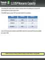
1.2 DSP Resource Capacity
Each optional DSP card provides a number of resources that can be called upon to provide VOIP
processing when the system requires them.
(The NS1000 requires at least 1 DSP card to be installed for it to operate.)
Model
Card Name
Resources
KX-NS0110
DSP-S
63
KX-NS0111
DSP-M
127
DSP-L
254
KX-NS0112
(Up to 2 DSP cards can be installed in each NS1000, therefore the maximum DSP resource available
per system is 508)
In Addition to the above ‘Free’ Resources, 2 Resources are always reserved for UM Tones – not programmable.
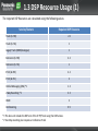
1.3 DSP Resource Usage (1)
The required DSP Resources are calculated using the following values
Service/Feature
Required DSP Resource
Trunk (G.729)
2.2
Trunk (G.711)
1
Legacy Trunk (ISDN/Analogue)
1
Extension (G.729)
2.2
Extension (G.711)
1
IP-CS (G.729)
2.2
IP-CS (G.711)
2
Unified Messaging (UM) *1
1.3
2-Way Recording *2
2.3
OGM
Conferencing
*1 This does not include the DSP cost of the IP-PT/Trunk using the UM Service.
*2 Two-Way recording also requires a Conference Trunk
2
0.5
1.3 DSP Resource Usage (2)
IP Phones – “P2P”
Call Setup Only
P2P Communication
1.
DSP is not used at any stage of a P2P call – DSP function is taken care of within handset itself
once connected.
2.
If selected compression method of phones differs, the handsets negotiate the lowest
bandwidth codec of the two:
(G729 > G711 > G722)
3.
This applies to both SIP and IP-PT types - makes no difference
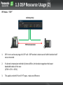
1.3 DSP Resource Usage (3)
IP-Trunk to IP-Extension
DSP Cost
2.2
DSP Cost
1
NS1000
IP-Trunk
G.729
G.711
IP-PT
From the previous Resource table, we can calculate the DSP Resources required for the
above call scenario:
2.2 + 1 = 3.2 DSP Resources Required
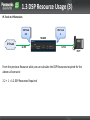
1.3 DSP Resource Usage (4)
Unified Messaging Access (MSG Playback)
DSP Cost
1
DSP Cost
1.3
G.711
IP-PT
UM
Recording or playing back messages from the UM requires DSP Resource. For this
example, the following DSP Resource is required:
1.3 + 1 = 2.3 DSP Resources Required
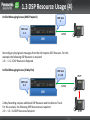
Unified Messaging Access (2-Way Rec)
DSP Cost
1 + 0.5
DSP Cost
2.3
IP-PT
G.711
UM
2-Way Recording requires additional DSP Resource and Conference Trunk.
For this scenario, the following DSP Resources are required:
2.3 + 1.5 = 3.8 DSP Resources Required
IP-PT
1.3 DSP Resource Usage (5)
Conferencing (Example – 6pty conference).
DSP Cost
4.4 (2.2X2)
NS1000
IP-Trunk
G.729 (x2)
DSP Cost
3 (6X0.5)
DSP Cost
1
G.711
IP-PT
Conferencing
DSP Cost
4.4 (2.2X2)
IP-Trunk
G.729 (x2)
DSP Cost
1
Must assign 1 DSP cost
for analogue
Conferencing.
SLT
A conference requires additional resources to handle multiple voice channels.
Also, in standard two-way conversations, analogue lines do not require any DSP resources, but in a
conference they do.
In addition, IP trunks in a conference require additional DSP resources.
For this example the number of required resources are 4.4 + 4.4 + 3 + 1 + 1 = 13.8.
1.4 DSP Resource Usage - Summary
DSP Resource Summary
• Accurate DSP selection is only possible when you know the maximum concurrent scenarios that
will be required by the system
• In most cases, IP phones used in the office will use G722 for extension to extension calls and G711
for ISDN trunk calls so DSPs are used lightly.
• Typically only remote IP phones would use G729 mode. (Low Bandwidth)
• SIP trunk providers can use either G711 or G729 – available bandwidth on the internet/broadband
service will dictate if G711 or G729 is used.
• Use the NS1000 DSP Resource tool and Usage graph to guide you to the required DSP card.
NS1000
DSP RESOURCE ADVISOR
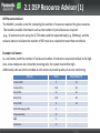
2.1 DSP Resource Advisor (1)
DSP Resource Advisor
The WebMC provides a tool for calculating the number of resources required for given scenarios.
The Installer provides information such as the number of ports/resources required
(e.g., 16 extension ports using the G.729 codec) and the expected load (e.g., 50%busy), and the
resource advisor calculates the number of DSP resources required to meet those conditions.
Example: Call Centre
In a call centre, both the number of trunks and number of extensions required are likely to be high.
Also, since employees are constantly receiving calls, the system load will be high.
Additionally, calls are often recorded at call centers to provide quality-of-service monitoring.
Service
Ports
Busy Ratio (%)
Trunks (G729)
8
50
Trunks (G711)
128
80
Exts (G729)
32
50
Exts (G711)
128
80
IP-CS (G729)
8
50
Unified Messaging (UM)
8
-
2-Way Recording
12
-
OGM
4
-
Conference
12
-
2.1 DSP Resource Advisor (2)
Example: Call Centre (Cont..)
The Web MC DSP Resource advisor can be used to select the necessary DSP combination
‘SETTINGS’ -> PBX Configuration -> 1. Configuration ->
5. DSP Resources -> 1. Setting
Select DSP Resource Advisor
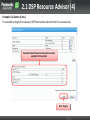
2.1 DSP Resource Advisor (3)
Example: Call Centre (Cont..)
Enter the Scenario details;
Select the desired DSP combination to
give you enough DSP Resource.
Check there is sufficient
‘Free’ Resource
In this example, it can be seen that both a DSP-L (252) and DSP-S (63) will be required.
(Total 315 Available Resources)
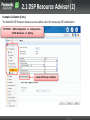
2.1 DSP Resource Advisor (4)
Example: Call Centre (Cont..)
It is possible to Apply the necessary DSP Reservation scheme from this scenario also:
Recommended Resource Reservation can be
applied to the system
Click ‘Apply’
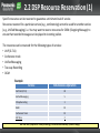
2.2 DSP Resource Reservation (1)
Specific resources can be reserved to guarantee a minimum level of service.
Resources reserved for a particular service (e.g., conferencing) cannot be used for another service
(e.g., Unified Messaging). i.e. You may want to reserve resources for OGM (Outgoing Message) to
ensure that recorded messages can be played to incoming callers.
The resources can be reserved for the following types of services:
• VoIP (G.711)
• Conference trunk
• Unified Messaging
• Two-way Recording
• OGM
Example
Service
Simultaneous Operation
VoIP Call (G711)
40
Unified Messaging
5
2-Way Recording
3
OGM
10
Conference Trunk
10
UM Tone
2
NB: UM Tone (required for 2-way recording) is reserved automatically (cannot change)
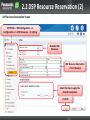
2.2 DSP Resource Reservation (2)
DSP Resource Reservation Screen
‘SETTINGS’ -> PBX Configuration -> 1.
Configuration -> 5. DSP Resources -> 1. Setting
Available DSP
Resource
DSP Resource Reservation
+ ‘Free’ Resource
Select the time to apply the
desired reservation
Click OK
2.3 DSP Usage Graph
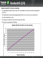
DSP usage graph
The PBX keeps a record of the maximum DSP usage per hour for each of the following features/services.
• VoIP (IP trunk, IP extension and IP-CS usage)
• Conference
• Unified Messaging
• OGM
• Two-way recording
This data is displayed via the WebMC and shows trends in DSP usage over time, as well as the number of
calls / operations abandoned due to lack of resources. (Up to 30 days usage is logged)
The graph allows you to confirm that sufficient resources are available, or if a larger DSP is required.
‘SETTINGS’ -> PBX
Configuration -> 1.
Configuration -> 5. DSP
Resources -> 2. Usage
Time Frame
EXAMPLE ONLY!
DSP RESOURCES COMPLETE
Section - 6
NETWORKING
Contents
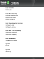
Chapter 1 Introduction
1-1. Introduction
Chapter 2 One-Look Networking
2-1. One-Look Networking Concept
2-2. Main One-Look Features
2-3. Master and Slave Unit
Chapter 3 One-Look Networking: System Design
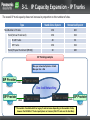
3-1. IP Capacity – Trunks
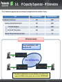
3-2. IP Capacity – Extensions
Chapter 4 Peer – to- Peer (P2P) Networking
4-1. Peer to Peer Communication
4-2. Peer to Peer Group Setting
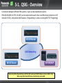
Chapter 5 QSIG Networking
5-1. QSIG Networking Overview
Appendix 1
Bandwidth
Appendix 2
IP Port Security
Chapter 1
INTRODUCTION
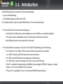
1-1. Introduction
KX-NS1000 provides two methods of private networking:
1. One-Look Networking
2. QSIG Networking (via ISDN and H.323)
This module will focus on the new NS1000 feature “One-Look Networking”.
• The main benefits of One-look networking are;
• It looks like one PBX system, even though two or more PBXs are networked together.
• The system can be expanded easily via a Web based maintenance console.
• No additional servers are required for call control.
• The main differences between “One-look” and “QSIG” Networking are the following;
• For “One-look”, the ‘Master’ PBX controls all extensions within the network.
In a “QSIG” network, each PBX controls its own extensions.
• For “QSIG”, each PBX needs to be programmed individually.
For “One-look”, almost all settings are made in the master PBX only.
• “QSIG” is suitable for connecting the NS1000 to the existing KX-TDE/NCP systems, or when
there are 17 or more NS1000s in the network.
• “One-Look” is available for up to 16 connected NS1000 systems (Max)
Chapter 2
ONE-LOOK NETWORKING
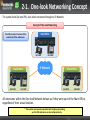
2-1. One-look Networking Concept
The system looks like one PBX, even when connected though an IP Network
Concept of One-look Networking
The PBX located at the head office
controls all of the extensions.
Head Office
Ext.1001
IP Network
Branch Office
Ext.1101
Ext.1002
Ext.1102
Branch Office
Ext.1201
Ext.1202
All extensions within the One-look Network behave as if they were part of the Main Office,
regardless of their actual location.
* The network can be easily expanded with simple programming.
- up to 1,000 extensions can be configured easily.
2-1. One-look Networking Concept
The Master Unit controls one or more Slave Units (15 Max).
Physical Connection of One-look Networking
Head Office
Master Unit
PTSN
PTSN
Branch Office
IP Network
Branch Office
Slave Unit
The PBX located at the branch
office is called the “Slave Unit”.
Slave Unit
If ‘Slave’ units are installed in Branch Offices, local calls can be made using local trunks.
The Slave units can also support additional extensions and UM features.
NB: System redundancy is not supported, if the Master unit fails, calls will not be possible via the Slave units (TBC)
2-1. One-look Networking Concept
Specifications
The maximum number of units within an one-look networking is 16.
• Master : 1
• Slave : 15
The maximum number of extensions within an one-look networking is 1,000.
• Max. 1,000 extensions
/ networked system
• Max. 640 extensions * / site (unit)
SIP Phone : 640
• IP-PT and IP Softphone : 128
• Extension (SLC on Physical Extension Card) : 2
No external (additional) server for network call control is required.
• Major competitors need server for 5 or more PBXs.
The one-look network should be consist of the PBXs which have the same model suffix of model
number (e.g., KX-NS1000NE), This information can be found on the name plate).
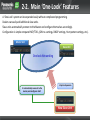
2-2. Main ‘One-Look’ Features
A ‘One-Look’ system can be expanded easily without complicated programming.
Dealers can easily add additional slave units.
Slave units automatically connect to the Master and configure themselves accordingly.
Configuration is simple compared NCP/TDEs, (GW no. settings, DN2IP settings, Hunt pattern settings, etc.).
Master Unit
Slave Unit
One-look Networking
2. Automatically connects to the
master, and configures itself.
1. System Expansion
New Slave Unit
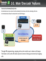
2-2. Main ‘One-Look’ Features
Trunk calls via Remote (Slave) Units.
An extension user can access trunks connected to remote units thus reducing call costs.
An International call can be reduced to Local Call charges.
Head Office
PTSN
Hamburg
Local Call
Paris
Ext.1001
PTSN
Branch Office
One-look Networking
Internal Company Call
(No charge)
Total call charges
can be reduced.
Ext.1101
Through ARS programming, outgoing calls can be routed so as to reduce call charges.
The Master unit has the ARS tables (System Common Setting) and controls all outgoing
calls.
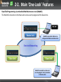
2-2. Main ‘One-Look’ Features
Simplified Programming via embedded Web Maintenance tool (WebMC)
The Web MC connection to the Main unit can be used to program all the Slave Units.
Web MC
Master Unit
Web MC connected to Master can
configure both Master and Slave Units.
One-look Networking
Slave Unit
Slave Unit
Web MC connected to a Slave unit
can only program ‘local’ parameters
of the Slave Unit.
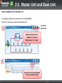
2-3. Master Unit and Slave Unit
Master and Slave units are the same physical PBX model.
The PBX mode (Master or Slave) is set via system programming (Initialization).
The key parameters assigned to each unit are:
• Master : PBX Type=Master + IP address
• Slave : PBX Type=Slave + IP address + IP address of the master unit
The PBX mode (Master or Slave) is indicated by the (MASTER) LED on the front of the unit.
Indicators
STATUS
BATT
ALARM MASTER
Master : Green ON
Slave : Amber ON
2-3. Master Unit and Slave Unit
Common and Individual Unit Settings
To configure One-Look Networking, some settings must be configured for each individual unit.
Main Settings
Common Settings (Master)
- Numbering Plan
- COS
- Group Settings
- Extension Settings
- Co Line Settings
- DDI/DID Table
- TRS
- ARS
- etc.
Individual Settings (Master & Slave)
- Slot (Installing Physical and Virtual card)
- Card and port property
- IP Terminal Registration
- Network service (IP address, DHCP server, etc.)
- E-mail Notification
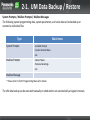
- Data backup / restore
- etc.
“Common settings” include Numbering Plan, COS, Group settings, etc.
“Individual Settings” include Installing Physical and Virtual cards, IP terminal registration,
etc.
2-3. Master Unit and Slave Unit
How to configure each individual unit
To configure each unit, select the unit via the Web MC.
There are two ways to select the desired unit
Via ‘Home’
Screen Icon
1
Right-click the unit to be
configured, and select
“Maintenance” or “Setup”.
2
Select the unit to be configured
from the pull-down menu.
2-3. Master Unit and Slave Unit
The Site ID is used for “Common settings”.
The Site ID is assigned to each unit via the “Add Site” Wizard.
On the PBX setting screen, the Site ID is used instead of “Site name”.
Extension Setting example
“Site” column
* The “Site ID” is used for “CO Line Settings”, “DIL Table & port Settings”, “Door-phone”, “External Relay”, “External Sensor”, etc.
* To confirm the Site ID, click “List View” on the Home screen.
Chapter 3
ONE-LOOK NETWORKING:
SYSTEM DESIGN
3-1. IP Capacity Expansion - IP Trunks
The overall IP trunk capacity does not increase in proportion to the number of sites.
Type
Stand Alone System
Networked System
256
600
Trunk (Virtual Trunk Card)
256
256
H.323 Trunks
48
96
SIP Trunks
256
256
30
480
Total Number of Trunks
Trunk (Physical Trunk Card (PRI30))
SIP Trunking example
Max. per networked Systems ->256ch.
Max. per site -> 256
SIP Provider
100ch
One-look Networking
SIP Provider
100ch
56ch
SIP Provider
* The number of available H.323 or Legacy Trunks increases depending on the number of sites,
however the OVERALL IP Trunk capacity does not increase (256 IP Trunks over 16 sites Max).
3-2. IP Capacity Expansion - IP Extensions
The IP extension capacity does not increase in proportion to the number of sites.
Type
Stand Alone System
Networked System
640
1,000
Extension (Virtual Extension Card)
640
1,000
IP-PT and IP Softphone
128
1,000
SIP (UT & 3rd Party) Phone
640
1,000
2
32
Total Number of Extensions
Extension (Physical Extension Card (SLC)
SIP-Extension example
Max. per networked Systems ->1000.
Max. per site -> 640
300
640
One-Look
One-look
Networking
Networking
60
* The number of available extension increases depending on the number of sites,
however the OVERALL Extension capacity does not increase PROPORTIONALLY.
Chapter 4
PEER – TO- PEER (P2P)
NETWORKING
4-1. Peer to Peer (P2P) Communication
Peer to Peer (P2P) Communications.
The NS1000 automatically establishes peer-to-peer communication between peer-to-peer
compatible IP extensions (i.e., NT3xx and UT series) that belong to the same P2P group.
Non P2P Calls require DSP Resource.
Non-P2P Path
P2P Path
P2P Path
DSP Required
NT3xx
NT3xx
P2P Group 1
P2P Group 2
UTxxx
P2P Group 2
UTxxx
P2P Group 2
By using Peer to Peer mode, we can:
- Potentially reduce network wide traffic to the PBX
- Improve voice quality for P2P calls (By using G722 codec – Only supported for P2P
Note: P2P cannot be disabled but, using P2P Group function, phones assigned to different P2P Group can make non P2P calls.
calls)
4-2. P2P Group Setting
The P2P Group for IP-Extensions can be set in the appropriate Port-Properties screen;
‘Settings’ -> PBX Configuration -> Slot
-> Virtual Cards -> Port Properties
The P2P Group for the desired
extension can be set here.
NB: IP-CS do not support P2P communication, so no P2P Group setting is available for IP-CS.
Chapter 5
QSIG NETWORKING
5-1. QSIG - Overview
Connections between different PBX systems / types can be established via QSIG.
PBXs (KX-NS1000, KX-TDE, KX-NCP) can be connected to each other via ISDN private network or VoIP
network (H.323), and provide QSIG features. (Programming is same as existing NCP/TDE Programing)
NS1000 Master
QSIG Networking
NS1000 Master
KX-TDE/NCP
When using QSIG enhanced features, KX-TDE / NCP must be with MPR software version 4.1000 or later.
When using QSIG enhanced features, Activation Keys are needed.
Appendix 1
BANDWIDTH
Bandwidth (1/4)
Bandwidth for voice data, call control (signalling), and system control between units must be
considered when site planning.
Required Bandwidth per Call for Voice : Determined by CODEC and Packet Sending Interval
CODEC
Packet Sending Interval
20ms
30ms
40ms
60ms
G.711 / G.722
80kbps
74.7kbps
72kbps
69.4kbps
G.729A
24kbps
18.7kbps
16kbps
13.4kbps
Required Bandwidth per Call for Signaling
Phone Type
Required Bandwidth
IP Telephones (except SIP phones)
7.2kbps
SIP Phone
16.0kbps
NB: In addition to the above, Basic Ethernet frame, VPN headers, etc., should also be considered.
Bandwidth (2/4)
Network bandwidth for One-look networking
• The signaling data traffic between main unit is estimated by the number of extension deployed in
main unit.
• The table below shows estimated signaling data traffic in case 2 main units are connected as
one-look networking in a pair.
• The values are calculated in case the most busy hour traffic.
• The system is essentially non-blocking.
Bandwidth (3/4)
Example of One-look networking configuration
Signaling
RTP
- RTP codec :G.711
- Packet interval :20ms
Master:
150 Extensions
Number of simultaneous calls: 26*
Signaling: 416 kbps
RTP: 4,160kbps
*Number of 100 extn. in busy hour
B
A
Number of simultaneous calls: 12*
Signaling: 256 kbps
RTP: 1,920kbps
*Number of 50 extn. in busy hour
Network
IPIPNetwork
Slave 1:
100 Extensions
C
Number of simultaneous calls: 12*
Signaling: None (included A and B)
RTP: 1,920kbps
*Number of 50 extn. in busy hour
Slave 2:
50 Extensions
Bandwidth (4/4)
Assessing bandwidth – Example
Master Unit
Slave Unit
IP Network
CODEC : G.711
Packet Interval : 20ms
Number of Extensions : 50
Extension Type : SIP Phone
Number of Simultaneous Calls : 16
Bandwidth required for Voice data
= Number of simultaneous calls x 2 x Required bandwidth for codecs (kbps)
= 16 x 2 x 80 = 2560kbps
Bandwidth required for Signalling
= Number of simultaneous calls x signalling bandwidth per call for SIP phones (kbps)
= 16 x 16 = 256kbps
Total required bandwidth
= Bandwidth required for Voice data (kbps) + Bandwidth required for signalling (kbps)
= 2560 + 256 = 2816kbps
* In this example, Basic Ethernet frame, VPN headers, system control data, etc., are not considered.
Appendix 2
IP-PORT SECURITY
Port Security
Port Security
If the VoIP network contains a firewall, the firewall must be configured appropriately to allow VoIP
packets to pass through certain ports of the ports listed below without being blocked by filtering.
The ports for which you need to configure the firewall may vary depending on the network
conditions.
For more information, consult your network administrator.
The following tables show the PBX ports used for IP communications.
Any access to the ports not on these lists are ignored.
Port Numbers (Default) (1/5)
LAN Port Numbers
Port Number
Protocol
Application
Client/Server
Changeable/ Fixed
8080
TCP
Web Maintenance Console
-
Changeable
9300
UDP
PTAP
-
Changeable
10000– 10655
TCP
-
Changeable
20000
TCP
UM-VMA*3
Server
Fixed
30021
TCP/UDP
FTP/FTPS
Server
Changeable
H.323 Dynamic Port (H.225 Send, H.245 Send/ Receive,
Connection-less [TCP] Send Port)
30022
TCP
SSH
Server
Changeable
32727
UDP
MGCP*1 for IP-CS
-
Changeable
ACS-MDW
Server
Fixed
TCP
Access Point Login (Telnet)
Server
Changeable
33090
33091
33092
33131
33321
UDP
TCP
33333
TCP
CTI 3rd Party Connection
-
Changeable
33334
TCP
CTI 1st Party Connection
-
Changeable
33478
UDP
STUN
Client
Changeable
33702
UDP
ACS-MDW (WSD)
Server
Fixed
35060
UDP
SIP UA (CO)
-
Changeable
39300
UDP
PTAP for IP-CS
-
Changeable
40000– 40095
TCP/UDP
FTP/FTPS-Data
Server
Changeable
UDP
SNMP TRAP
Client
TCP/UDP
FTP
Client
TCP/UDP
FTP/FTPS-Data
Client
UDP
NTP
Client
50000– 65535
UDP
DNS
Client
(Ephemeral)
UDP
SYSLOG
Client
TCP/UDP
SMTP
Client
TCP/UDP
SMTP over SSL
Client
TCP/UDP
POP3
Client
Fixed
Port Numbers (Default) (2/5)
MNT Port Numbers (1)
Port Number
Protocol
Application
Client/Server
Changeable/ Fixed
21
TCP/UDP
FTP/FTPS
Server
Changeable
25
TCP/UDP
SMTP
Server
Changeable
53
UDP
DNS
Server
Changeable
67
UDP
DHCP
Server
Changeable
80
TCP
HTTP
Server
Changeable
123
UDP
NTP
Server
Fixed
143
TCP
IMAP
Server
Changeable
161
UDP
SNMP
Server
Changeable
443
TCP
HTTPS
Server
Changeable
465
TCP/UDP
SMTP over SSL
Server
Changeable
993
TCP
IMAP over SSL
Server
Changeable
2103
TCP
CMM
Server
Fixed
2300
TCP
Telnet-SMDR
-
Changeable
3493
UDP
UPS*1
-
Fixed
3702
UDP
WSD
Server
Changeable
7574
TCP
CWMP
Server
Changeable
8080
TCP
Web Maintenance Console
-
Changeable
30022
TCP
SSH
Server
Changeable
ACS-MDW
Server
Fixed
33090
30091
30092
33131
UDP
TCP
33321
TCP
Access Point Login (Telnet)
Server
Changeable
33333
TCP
CTI 3rd Party Connection
-
Changeable
33334
TCP
CTI 1st Party Connection
-
Changeable
33702
UDP
ACS-MDW (WSD)
Server
Fixed
Port Numbers (Default) (3/5)
MNT Port Numbers (2)
Port Number
Protocol
Application
Client/Server
Changeable/ Fixed
40000– 40095
TCP/UDP
FTP/FTPS-Data
Server
Changeable
UDP
SNMP TRAP
Client
TCP/UDP
FTP
Client
TCP/UDP
FTP/FTPS-Data
Client
UDP
NTP
Client
50000– 65535
UDP
DNS
Client
(Ephemeral)
UDP
SYSLOG
Client
TCP/UDP
SMTP
Client
TCP/UDP
SMTP over SSL
Client
TCP/UDP
POP3
Client
TCP/UDP
ACS-MDW
Server
Fixed
Port Numbers (Default) (4/5)
DSP Port Numbers (1)
Port Number
Protocol
Application
Client/Server
Changeable/ Fixed
21
TCP/UDP
FTP/FTPS
Server
Changeable
25
TCP/UDP
SMTP
Server
Changeable
53
UDP
DNS
Server
Changeable
67
UDP
DHCP
Server
Changeable
68
UDP
DHCP
Client
Changeable
123
UDP
NTP
Server
Fixed
143
TCP
IMAP
Server
Changeable
161
UDP
SNMP
Server
Changeable
465
TCP/UDP
SMTP over SSL
Server
Changeable
993
TCP
IMAP over SSL
Server
Changeable
2103
TCP
CMM
Server
Fixed
3493
TCP
UPS
-
Fixed
3702
UDP
WSD
Server
Changeable
7547
TCP
CWMP
Server
Changeable
8000
UDP
Conference*1
-
Fixed
8080
TCP
Web Maintenance Console
-
Changeable
Port Numbers (Default) (5/5)
DSP Port Numbers (2)
Port Number
Protocol
Application
Client/Server
Changeable/ Fixed
12000 – 13535
UDP
RTP/RTCP
-
Changeable
16000 – 18047
UDP
RTP/RTCP for NAT traversal
-
Changeable
30022
TCP
SSH
Server
Changeable
ACS-MDW
Server
Fixed
33090
33091
33092
33131
UDP
TCP
33702
UDP
ACS-MDW (WSD)
Server
Fixed
40000 – 40095
TCP/UDP
FTP/FTPS-Data
Server
Changeable
UDP
SNMP TRAP
Client
TCP/UDP
FTP
Client
TCP/UDP
FTP/FTPS-Data
Client
UDP
NTP
Client
50000 – 65535
UDP
DNS
Client
(Ephemeral)
UDP
SYSLOG
Client
TCP/UDP
SMTP
Client
TCP/UDP
SMTP over SSL
Client
TCP/UDP
POP3
Client
TCP/UDP
ACS-MDW
Server
Fixed
NETWORKING COMPLETE
Section - 7
FILE MANAGEMENT
SYSTEM UPGRADE (PCMPR)
BACKUP (DCSYS)
OGM
MOH
BGM UPLOAD
BACKUP
SETTING
Contents
0.0 Upgradeable Firmware
1.1
1.2
1.3
1.4
PBX Firmware version
System Firmware Download
System Firmware Upgrade
Check Firmware version
2.1
2.2
2.3
2.4
System Backup to USB
System Restore from USB
System File Backup – PC
System File Restore – PC
3.1 OGM File Upload – PC
3.2 OGM Recording – PT
3.1 MOH/BGM File upload
4.1
4.2
4.3
4.4
4.5
MOH/BGM File Status
MOH/BGM File Upload
MOH/BGM File Deletion
MOH/BGM File Backup
MOH/BGM File Assignment
FIRMWARE UPGRADE
0.0 Upgradable Firmware by WebMC
The following firmware can be managed and uploaded via the WebMC .
Firmware upgrade of DECT PS is not possible with TCA/WT Handsets and NS1000 V1.0
IMPORTANT:
Do not change the Filename of the Firmware files – System upgrade will not be possible if the files are named in an incorrect format.
1.1 PBX System Firmware Version
Over the course of the life of the PBX system and terminals etc, it is necessary to keep the System
Firmware updated so that the latest features and improvements can be enjoyed.
The Firmware version the PBX system is currently running can be seen below
Select the ‘Home’
screen.
In a Onelook System, all registered units (Master + Slave)
information will be displayed on this screen.
The PBX system’s
• Mode
• IP-Address
• MAC Address
• Firmware (PBX) Version
• Region
Can be seen here.
1.2 System Firmware Download
Before the system or it terminals can be upgraded, new Firmware must first be downloaded to the
System. This can be a Manual or Automatic process depending on the system settings;
Manual Download (1) - Download from PC
Select the
Maintenance screen
Select the location of the new
Firmware file. Click ‘Execute’
Click ‘OK’ and the prompt, and the
Download process will start.
File Download takes approximately 4~5 min for PCMPR (PBX System) firmware
1.2 System Firmware Download
There are several other methods available to Download the Firmware files; PC, USB, FTP and a PBX
Master system
Manual Download (2) - Download from USB
Select USB Memory, and ensure the USB
Device containing the Firmware file is
connected to the system.
Select the desired file and click ‘Execute’
If a USB memory device is inserted into the PBX, the contents of the following directory
on the device will be checked for updated files: /private/meigroup/psn/ippbx/update
1.2 System Firmware Download
To support FTP download, the details of the desired FTP server must first be set in the PBX system
Manual Download (3) - Download from FTP (Available from MASTER Unit only)
Select the ‘Settings’ screen and ‘Network Service’ ->
‘Client Features’ -> 1. FTP
Set the FTP connection name, IP
Address, Port Number, login details and
Protocol of the desired FTP Server.
1.2 System Firmware Download
Once the FTP Server location is set, the download can be started from the Maintenance screen
Manual Download (3) - Download from FTP (Available from MASTER Unit only)
Select the Download Location
Set the FTP connection path
and download folder.
Click ‘Get File’.
1.2 System Firmware Download
A Slave PBX can also obtain it’s firmware from a MASTER
Manual Download (4) - Download from MASTER PBX
Select the Download Location
Select the file to download
(Only most recently downloaded files are displayed)
NB: PCMPR file is shown here, but CS, UT, NT and LPR firmware is also available to download
1.2 System Firmware Download
It is possible to download all available firmware updates automatically from an FTP server.
It is also possible to set the system to automatically check for updates at a specific time/day.
Automatic Download (4) - Download from FTP Server – MASTER UNIT ONLY
Select ‘Automatic’
Select the FTP Server location (Pre-programmed in
‘Settings’ Screen) and the Folder name containing the
update firmware.
Select the Time/Date to check
for new firmware
You can chose to download the new files automatically, or
send an email notification that new downloads are available.
The Installer can then manually download the files
The download process can be cancelled if necessary
1.3 PBX System Firmware Upgrade (1)
Once download, the new firmware can be ‘pushed’ to the relevant device Manually or Automatically
System Upgrade (1) - Manual
1. System Control -> Program Update -> Update Program File
2. Select the Update Type (Manual, Timed or Cancel)
3. Select Email notification recipients
4. Select the File to be used for the upgrade
6. Select ‘Apply’, then
‘Execute’ to start the
upgrade process
5. Select the upgrade
target (Device)
7. Click ‘OK’ to complete
1.3 PBX System Firmware Upgrade (2)
Devices can be upgraded automatically at a specified time.
System Upgrade (2) - Timed
Select ‘Timed Update’
Select the required ‘Update Time’
Select the upgrade
target (Device)
NB: Once devices have received the firmware updates, they will automatically re-boot – Take care at busy times!
If the upgrade process is made via a SLAVE Unit, only the SLAVE and Terminals registered to the SLAVE are upgraded.
1.3 PBX System Firmware Upgrade (3)
The Plug and Update feature allows IP-PTs to be automatically updated to the latest software version
when they are registered to the PBX.
Plug and Update
1. System Control -> Program
Update -> Update Program File
Select ‘On’ or ‘Off’(Default)
When Plug and Update is enabled, the version number of the system software stored on the Master unit is compared
to the system software currently in the IP-PT, after the IP-PT has been registered to the PBX.
If the software on the Main unit is newer, it is downloaded to the IP-PT.
Plug and Update can be enabled for each site in a One-look network.
The Plug and Update screen lists the PBXs in the One-look network by site number and site name.
1.4 Check Firmware Version
It is possible to check the Firmware versions of each device
PBX Firmware version - check
The PBX Version can be viewed by
selecting the ‘Home’ screen and ‘List’ View
The PBX Firmware Version can be seen here
PBX SYSTEM BACKUP AND RESTORE
(NOT UM)
2.1 System Backup – to USB
A PBX’s system data can be backed up to a USB memory device inserted into the PBX’s USB port.
At a later time, the USB memory device can be used to restore the backed up system data to a PBX.
System Backup to USB
Tool -> System Data Backup to USB
Select the PBX System data to Backup.
You must Backup the System data if you wish to restore
the system at a later date.
Recommendation: Backup All Files
NB:
•The UPS connection must be removed before inserting the USB Device – re-connect it afterwards.
•UM data is backed up using a different process – only PBX data is backed-up by this process.
•Use a USB Device with minimum 512MB free space.
2.2 System Restoration – From USB
Restoring backed up data from a USB memory device to a PBX.
Follow the procedure below to restore the backed up data to a PBX.
Note: The restoration process requires that the PBX is initialised, which returns the PBX to its factory
default state.
Under the following conditions, restoration may not be possible, even though the PBX has been initialised.
• The USB memory device hardware is faulty.
• The data on the USB memory device has become corrupted.
• The USB memory device is removed from the USB port of the PBX during the restoration process.
To minimise the potential of a failed backup, connect the USB memory device to a PC to confirm the USB
memory device is operational and that the backup data is intact before starting this restore process.
1.
2.
3.
4.
5.
The PBX must be in a powered-off state.
Insert the USB memory device with the backup data into the USB port of the PBX.
Set the PBX’s System Mode Switch to the "SYSTEM INITIALIZE" position.
Turn on the PBX’s power switch. The STATUS indicator will flash green.
Slide the System Mode Switch back to the "NORMAL" position.
The restore process will begin and the STATUS indicator will flash rapidly.
When the restoration process is completed, the PBX will restart automatically.
2.3 System File Backup - PC
A PBX’s system data (DCSYS File and LICxx Files) can be backed up to PC if a USB device is not available.
At a later time, the files can be transferred back to the PBX and a restore made.
Tool -> File Transfer PBX to PC
Save the File to your PC
Select the desired file and click
‘Transfer’
NB: Backup LICxxx files also – these are you’re A/K files!
It is possible to restore the system using the ‘File Transfer PC to PBX tool, followed by a system Reset (via WebMC).
2.4 System File Restore – PC (1)
A PBX’s system data (DCSYS File and LICxx Files) can be restored from a PC .
Tool -> File Transfer PC to PBX
Browse for the desired file (DCSYS or LICxxx)
and click ‘Execute’
NB: Only 1 file can be transferred at a time
2.4 System File Restore – PC (2)
The files will be transferred from the PC to the PBX.
One the transfer is completed, you will need to
Restart the PBX via the WebMC.
2.4 System File Restore – PC (3)
Select ‘System Reset’ to make the transferred file active .
System Control ->
4. System Reset
Be sure to select ‘Skip’ when prompted,
otherwise the transferred file will be lost.
Click ‘OK’ at the prompts and the system will
Restart (All services/Terminals will be OUS
while restarting.
OGM
OUT GOING MESSAGES
3.1 OGM File Upload - PC (1)
A maximum of 64 Outgoing messages (OGM)can be recorded on a PBX.
In a One-look network, 64 messages can be recorded at each site (Max 64min recording time per site).
Using a PC, OGM files can be easily managed between PBX Units.
It is also possible to download MSG files from the PBX using the ‘MSG Transfer to PC’ Utility.
Messages downloaded to a PC are WAV (G.711a/μ) format.
Messages uploaded from a PC must be in one of the following formats:
WAV (linear PCM) or WAV (G.711a/μ).
Utility -> 2. File -> 3. MSG
Transfer to PBX
Select the target system and
OGM Index Number (1~64)
Browse to the desired MSG File
Click ‘OK’
Messages at all sites can be recorded, listened to, and deleted using the Master unit. However, in operation a PBX can only use messages stored locally.
E.g. when incoming callers queue, only an OGM from the PBX at which the callers are queuing can be used. An OGM from another site cannot be used.
3.2 OGM Recording – IP-PT
The manager extension (COS Setting) can record three kinds of greeting messages (OGM) as follows:
1. DISA message: Used to greet and guide callers.
2. Incoming Call Distribution Group message: Used to greet and guide callers to an ICD-G
3. Timed Reminder message: Used for a wake-up call message.
OGM recording can be accomplished via a Manager Extension using the sequence below
To Record
To specify a site ID
(if necessary)
3
Off-hook.
Enter
9
6
site ID
Enter 9 and
site ID (2 digits: 01–16).
36.
1
Enter 1.
OGM floating
extension no.
Enter OGM floating
extension number.
Progress
Tone &
C.Tone
C.Tone
The message
is played back.
Press STORE.
Record
message.
On-hook.
When the time limit passes,
it stops automatically.
To Playback
To specify a site ID
(if necessary)
3
Off-hook.
Enter
6
36.
9
site ID
Enter 9 and
site ID (2 digits: 01–16).
2
OGM floating
extension no.
Enter 2.
Enter OGM floating
extension number.
C.Tone
The message
is played back.
On-hook.
MOH (MUSIC ON HOLD)
BGM (BACKGROUND MUSIC)
UPLOAD / BACKUP
4.1 MOH/BGM File Status
Initially, a preinstalled audio file is set as the audio source for BGM 1.
Through system programming, this file can be removed or replaced like any other BGM audio file.
However, if the PBX is re-initialised, this preinstalled audio file is set to BGM 1 again.
The ‘Default’ MOH file details (and additional
files when they are loaded) can be seen via:
System Control -> 2. MOH -> 3. Status / Backup
Remaining Capacity Time
Filename and Filesize can be see here, together with the option to Backup
Notes
• Users logged in to the Master unit can see the status of all One-look network sites. Users logged in to a Slave unit may only view the status of that PBX.
• Only WAV files can be installed and file names must not exceed 14 ASCII characters in length.
• Files may not be larger than 80 MB.
• User (User) level accounts cannot perform this procedure.
4.2 MOH/BGM File upload
MOH Files can be uploaded to 8 different BGM locations over multiple sites using a PC .
System Control -> 2. MOH ->
1. Install
1.Select the MOH file for Upload
2. Select the PBX Site and
Upload Time
3. Select the desired BGM Location (1~8)
[User-supplied audio files]
Audio files must meet the following specifications: – Format: WAV, – Size: 80 MB or less,
– Length: 8 minutes or less
Ensure any Music used is not subject to copyright/performance law in your country.
4. Click ‘Execute. The Upload will start
4.3 MOH/BGM File Deletion
MOH Files can be managed across all sites via the MASTER unit.
Existing files can be deleted, allowing new files to be uploaded in their place.
System Control -> 2. MOH -> 2. Delete
1. Select the site from which you wish to delete the
MOH/BGM Files from
2. Select which BGM locations to
delete (1~8 or All)
3. Click ‘Execute’
4.4 MOH/BGM File Backup
It is possible to backup MOH/BGM files to a PC.
In the event of a system failure, the files can be easily re-uploaded
System Control -> 2. MOH ->
3. Status / Backup
1. Select the PBX Site to
backup
2. Select files
to backup
[User-supplied audio files]
Audio files must meet the following specifications:
– Format: WAV, – Size: 80 MB or less, – Length: 8 minutes or less (TBC)
Ensure any Music used is not subject to copyright/performance law in your country.
3. Save the files to PC
4. Click ‘OK’
4.5 MOH/BGM Assignment
Via System Programming, the appropriate MOH/BGM source can be selected.
(For details of External MOH Sources, refer to the Installation Manual)
PBX Configuration -> 2. System ->
2. Operator and BGM
Select the source for BGM1, MOH and Transfer here
NB: User Defined MOH/BGM will not be heard when an IP Extension puts another IP
Extension on hold. The IP Extension will generate their own HOLD Tone.
(Any P2P communication (No DSP) will not hear User defined MOH)
Click ‘OK’
UPGRADE & BACKUP COMPLETE
Section - 8
MAINTENANCE
Contents
Chapter 1 System Shutdown - Reset
1-1. UPS Connection and Setting
1-2. System Shutdown with UPS
1-3. System Shutdown (Manual)
1-4. System Reset/Restart
1-5. FAX Card Restart
Chapter 2 UM Backup and Restore
2-1. UM Backup / Restore
2-2. Backing-up UM data (Manual)
2-3. Backing-up UM data (Scheduled)
2-4. Restoring UM Data
Chapter 3 System Alarms
3-1. System Alarms
3-2 . SNMP Agent
3-3. SNMP Agent Setting
3-4. SYSLOG
3-5. SMDR Via LAN
3-6. Alarms via CTI
3-7. Alarms via PT
Contents
Chapter 4 Email Notification
4-1. SMTP Client Settings
4-2. Email Notification Settings
4-3. Email Log
4-4. Test Email
4-5. Email Report
Chapter 5 Data Import and Export
5-1. Import / Export using .csv
Chapter 6 Extension Lists
6-1. Extension List View
Chapter 7 Port Settings
7-1. IP-Address settings / DHCP / DNS
7-2. Port Speed / Duplex and Mirror settings
7-3. PING
Chapter 8 Error Logs
8.1. Error Logs – meaning
8.2. How to get Error logs via WEB MC
Appendix 1 - MIB
Appendix 2 - Supported USB
Chapter 1
SYSTEM SHUTDOWN - RESET
1.1 UPS Connection and setting (1)
UPS (Uninterruptible Power Supply) Integration
Description
An uninterruptible power supply unit (UPS) is a device that supplies power for several minutes to a connected
device when a power failure occurs.
If the PBX is connected to a compatible UPS via USB when a power failure occurs, the PBX can determine
how much power remains in the UPS and shut down when the remaining power drops below a specified amount
to prevent data loss or corruption.
The following features are also available:
• Specify the remaining battery level at which to shut down the PBX.
• Receive e-mail notifications of changes to the status and availability of a UPS.
Conditions
• For details about UPS units that are compatible with the automatic shutdown feature of this PBX, consult your
dealer. If an incompatible UPS is connected and the UPS runs out of power, the PBX will turn off without shutting
down.
• The power cord and USB cable must be connected to the same UPS. Connecting them to different UPSs can
result in incorrect operation.
IMPORTANT
• When power is restored after a power outage, the PBX operates in the following manner:
− If the PBX did not shut down, normal operation continues uninterrupted.
− If the PBX shut down and power remains in the UPS, the PBX must be started again manually.
(The power switch must be turned off and then on again.)
− If the PBX shut down and no power remains in the UPS, the PBX starts automatically.
(This is because the PBX's power switch is on.)
1.1 UPS Connection and setting (2)
1. Connect the UPS as described in the Installation manual
2. Set the NS1000 Shutdown threshold via the WebMC
Maintenance -> Status -> Equipment Status -> 1. UPS
UPS Status can be seen here
Set the UPS Battery Level, that
when reached, will cause the
PBX to Shutdown
NB: UPS Status alerts can also be sent via email.
1.2 System Shutdown with UPS
The UPS Provides a Safe Shutdown Process during AC Power Failure
Because the NS1000 system uses a Linux Based OS, the KX-NS1000 must be powered down using the
Shutdown process to avoid possible damage to the systems File Structure.
UPS Connection diagram and automatic shutdown process
2. The UPS supplies power to
the PBX (Using its battery).
NS1000 Power requirements (from the nameplate ratings)
Peak – 138VA (Watts)
RMS – 98VA (Watts)
RS232C is not supported for UPS
AC Cable
AC
Power
UPS
1. AC power is lost.
USB
Port
USB Cable
3. The UPS notifies that AC power is
lost and it’s remaining battery life.
4. KX-NS1000 executes
self shutdown at preprogrammed battery threshold.
NB: When NS1000 is ‘Shutdown’, it will not power back on automatically when
power is restored – the AC Switch needs to be switched OFF/ON
1.3 System Shutdown - Manual
The NS1000 system can be safely Shutdown by the following process
Maintenance -> System Control ->
5. System Shutdown
1a) Save the latest modification to Storage
Memory Card, and then shutdown.
1b) Shutdown now.
2.) Flashing Amber Amber ON
3.) Turn AC Switch OFF
1.4 System Reset/Restart
The NS1000 system can Reset/Restarted by the following process
Maintenance -> System Control -> 4.
System Reset
Save the latest modification to Storage
Memory Card, and then reset.
Reset now.
NB: This process does not set the system back to ‘Factory Default’.
To reset ALL settings, the system must be re-initialised.
1.5 FAX Card Reset/Restart
The NS1000 FAX Card (if fitted) can be safely Restarted by the following process
Maintenance -> System Control ->
3. Fax Card
Click ‘Execute’ and follow the Prompts.
Chapter 2
UM BACKUP AND RESTORE
2-1. UM Data Backup / Restore
System Prompts / Mailbox Prompts / Mailbox Messages
The following system programming data, system parameters, and voice data can be backed up or
restored as individual files
Type
Main Items
System Prompts
- Installed Prompt
- Custom Service Menu
- etc.
Mailbox Prompts
- Owner Name
- Personal Greetings
- etc.
Mailbox Message
* Please refer to the PC Programming Manual for details.
The UM data backup can be executed manually or scheduled to run automatically at regular intervals.
2.2. Backing up the UM Data (manual) (1)
Maintenance -> Tool-> 9.1 Manual backup
System Prompts settings
Select (Check) the
items to be backed up.
Mailbox Prompts settings
Select (Check) the
items to be backed up.
To configure more
detailed settings, click
these buttons.
Select (Check) the
items to be backed up.
Mailbox Message settings
2.2. Backing up the UM Data (manual) (2)
Mailbox Message settings example
Select (Check) the
mailboxes to be backed up.
Select (Check) the destination method.
2.2. Backing up the UM Data (manual) (3)
When “Local PC” is selected
When the message window is displayed, click “Save” , specify the
destination folder and file name, and save the backup files.
(Standard Windows Interface)
Confirm the
backup file size
and click “OK”.
When “USB (Main Unit)” is selected
When you select “USB (Master Unit)”, you can specify the
destination folder of the USB memory device.
* In this case, you
Confirm the
backup file size
and click “OK”.
* Ensure that the USB memory device is connected to the PBX and create the corresponding folder on the USB device in advance.
2.3. Backing up the UM Data (Scheduled) (1)
To create a new scheduled backup, “Add new entry” icon.
Maintenance -> Tool-> 9.2 Scheduled backup
Deletes the selected row
Edits the selected row
Adds new entry
Remove filter
2.3. Backing up the UM Data (Scheduled) (2)
You can select the following backup frequency.
Rule
Parameters - When the backup is executed
Daily
Hour, Minute
Weekly
A day of the week, Hour, Minute
Monthly
A day of the month, Hour, Minute
Yearly
A day of the year, Hour, Minute
Specific Date
A specific date, Hour, Minute
* Up to 20 backup events can be scheduled.
Weekly Backup example
Enter the description.
Select the rule.
Set the parameters.
Select (Check) the items to be backed up.
Selecting the items is same as the manual backup.
Please refer to chapter 4-6 for details.
2.3. Backing up the UM Data (Scheduled) (3)
Continued from the previous slide
Select (Check) the items to be backed up.
Selecting the items is same as the manual backup.
Please refer to chapter 4-6 for details.
2.3. Backing up the UM Data (Scheduled) (4)
A new scheduled backup is added.
The description you set and schedule
information will be displayed.
Activation Key (KX-NSU003) is required to use the scheduled backup feature.
2.4. Restoring the UM Data (1)
Maintenance -> Tool-> 10 UM data restore
Select an item to be restored.
* Multiple items can NOT be restored at one time.
2.4. Restoring the UM Data (2)
Continued from the previous slide
Restoring from the USB device
1. Select “USB (Main Unit)”, and specify the folder on the USB
device from where the backed up data is restored.
2. Click “OK” to execute.
* Ensure that the USB memory device is connected to the PBX.
Restoring from the PC
1. Select “File Import”, and specify the folder and the file name
on the PC from where the backed up data is restored.
(You can use “Browse” button.)
2. Click “OK” to execute.
Chapter 3
SYSTEM ALARMS
3.1. System Alarms
NS1000 can indicate that a system alarm occurred in several ways.
Error information (error codes, sub codes, etc.) are notified.
(Refer to Installation Manual for error code detail).
Syslog Server
IP-PT
FF key (System Alarm feature button) *
Standard Syslog Protocol
SNMP
Manager
SMDR
RS232C or Telnet
Standard SNMP
(V.1 and V.2)
E-mail
CTI
CSTA
PC
*: When a system error occurs, the button light turns on red. Pressing the button will show the error information on the display.
UT Series / SIP Phone does not support this feature.
3.2 SNMP Agent (1)
SNMP Agent Features
NS1000 includes SNMP features. It is possible for a PC assigned as an SNMP manager to manage and
receive PBX system status information, such as alarm information and general system activity using
SNMP.
Management Information Bases (MIBs) are sent to a PC (i.e., the SNMP manager) connected to the PBX
over a LAN and can then be stored and analyzed using SNMP manager software.
There are two monitoring methods, Polling and Trap
SNMP
Manager
Polling Method
Trap Method
Polling Method
The SNMP Manager sends request messages to collect the status of KX-NS1000, and then KX-NS1000
sends response to the SNMP Manager.
Trap Method
KX-NS1000 sends information when a status change occurs or an alarm is detected.
• Up to 2 SNMP managers can be assigned.
• This PBX supports SNMP Protocol Version 1.0 and SNMP Version 2c.
• This PBX can only receive read-only MIBs. Write MIBs are not supported.
• This PBX supports MIB II.
3.2 SNMP Agent (2)
The KX-NS1000 will send the following types of Trap.
Type
Standard Trap
Enterprise
Specific Trap *1
Trap Name
Description
cold Start
Information is sent after turning on the power of KX-NS1000 or
resetting KX-NS1000.
Authentication
Failure
Information is sent when an unregistered Community
Name and/or Manager IP address is entered.
Major Alarm
Information is sent when a major alarm is detected.
Minor Alarm
Information is sent when a minor alarm is detected.
Note: In addition to the standard SNMP v1 MIB files, the NS1000 supports the Panasonic Enterprise MIB
(Management Information Base) file for more detailed alarms.
This MIB file may be loaded into in the SNMP manager and it is available from the PCC CS website.
3.3 SNMP Agent Setting (1)
SNMP Agent Setting;
The SNMP Agent needs to be configured for the type of SNMP Manager being used.
‘Settings’ -> Network Service -> 3. Client Feature ->
3. SNMP Agent
Enable/Disable SNMP, Set
the SNMP Protocol (v1 or
v2c) and MIB Info.
Up to 2 SNMP managers
can be assigned.
3.3 SNMP Agent Setting (2)
SYSLOG (Trap Filtering)
The required TRAP output can be set.
In addition to the standard SNMP v1 MIB and MIB II files, the NS1000 supports the Panasonic
Enterprise MIB (Management Information Base) file for more detailed alarms.
This MIB file may be loaded into in the SNMP manager and it is available from the PCC CS website.
Refer to the Appendix for details of the Standard MIB.
3.4 SYSLOG (1)
NS1000 can send alarm information (Major alarm/Minor alarm) to a UDP Syslog server on port 514
(default).
By using Syslog, you can save all NS1000 alarms remotely to a PC.
These alarms may then be managed and responded to as required.
Alarm (Major/Minor)
Syslog Clients
Syslog Server
3.4 SYSLOG (2)
SYSLOG (System Settings)
The output of SYSLOG data needs to be enabled and the IP-Address/Host Name of the SYSLOG
Server need to be set.
‘Settings’ -> Network Service ->
3. Client Feature -> 2. SYSLOG
Enable / Disable SYSLOG data
SYSLOG Server address and port number
(514 default)
3.5 SMDR via LAN
SMDR(System Message Data Recording)
Call information (SMDR) can be output to the LAN (as well as via RS232c). Applications such as CA
Call Accounting can then use this information.
‘Settings’ -> Network Service ->
3. Client Feature -> 2. SYSLOG
Enter the SMDR port details (2300 default)
and the SMDR Password.
Further details? – Refer to the Feature Guide
3.6 CTI (TAPI / CSTA)
CTI (TAPI / CSTA) Under study
By connecting KX-NS1000 to a CTI server over a LAN, it is possible to output local alarm information
(major alarms/minor alarms) to a external PC.
EMCA CSTA Phase3
TAPI 2.1 based Panasonic original interface
3.7 System Alarms via PT
Settings to notify the system alarms via IP-PT
The extension numbers of IP-PTs that can display System Alarm Information.
Setup -> PBX Configuration -> 11.1 Main -> Maintenance Tab
Specify the extension numbers.
The System Alarm button setting (PT Flexible Button)
Setup -> PBX Configuration -> 4.1.4 Flexible Button
Select “System Alarm” as Type.
Chapter 4
EMAIL NOTIFICATION
4.1 SMTP Client Settings
SMTP settings (Email Client)
So that Email notification can take place, the SMTP Server details must be entered.
‘Settings’ -> Network Service ->
2. Server Feature -> 6. SMTP
Enter the SMTP Client/Server
information here.
Enter the details required by your Email Server. The NS1000 only sends email to the Server as a ‘Client’.
4.2 Email Notification Settings
Email Notification settings (System Alarms)
The system can be configured to automatically send notification emails in the case of System Alarms
or A/K Expiry.
‘Maintenance’ -> UTILITY ->
7. Email Notification -> 1. Alert
Set the Filter for Major/Minor or all alarms
Email Addresses and
subject are set here.
‘License expiry’ Notification Addresses are set here.
Notification will be sent 5 days before expiry.
4.3 Email Log Files
System Log Files (Email)
System Troubleshooting data files can be emailed from the system .
‘Maintenance’ -> UTILITY -> 7. Email
Notification -> 2. System Analysis
Select the desired
log file type..
This information, together with the system parameter file (DCSYS) or system backup, is required for
detailed fault analysis.
4.4 Test Email
TEST Email (SMTP Client)
To test the SMTP Client setting are correct, it is possible to send a test email.
‘Maintenance’ -> UTILITY -> 7. Email
Notification -> 3. Test Email
Enter the required email
addresses and subject field.
Click ‘Execute’ to send.
3.5. E-mail Report
E-mail sending status can be confirmed.
Maintenance -> Utility -> 5.4 E-mail Report
E-mail sending
status is displayed.
Chapter 5
DATA IMPORT AND EXPORT (.CSV)
5.1 Export / Import Tool (.csv) (1)
Several types of data can be exported / imported using the Web MC.
Exported data is saved as CSV file. The data can be imported to other units.
Master Unit
Export
Web MC
Master Unit
CSV Files
[Items]
-System Speed Dial
-Extension Name
-DDI/DID Number
-DDI/DID Destination
-Etc.
Import
Web MC
• The items to be exported / imported are selectable.
• The CSV file format is the same as KX-TDE/NCP. So, the CSV file exported from KX-TDE/NCP can be
imported to KX-NS1000. However, there is no ‘PBX-Replacement’ tool.
5.1 Export / Import Tool (.csv) (2)
Exportable / Importable items (List)
Using the Import/Export Tool, some data can be transferred between systems;
‘Maintenance’ -> Tool ->
6/7. Import/Export
Item
Description
Speed Dial and Caller ID
Name, Dial, CLI destination
Incoming Call - DDI/DID Table
DDI/DID Number, Name, Destination, Tenant, etc.
ARS - Leading Digit
Leading Digits, Additional Dial Digits, Route Plan Number
ARS - Except Code
Exception Code
ARS - Routing Plan
Routing Plan
Wired Extension
Extension Number, Name
PS Extension
Extension Number, Name
Quick Dial
Dial, Phone Number
SIP Extension
Extension Number, Password
V-IPGW16 GW Settings
GW Name, GW IP Address, Protocol, etc.
V-IPGW16 DN2IP
Leading Number, Remaining Number of Digits, etc.
V-SIPGW16 Settings
SIPGW16 Settings
V-SIPGW16 Provider
SIPGW16 Provider
*Refer to the PC programming Manual for details.
Chapter 6
EXTENSION LISTS
6.1 Extension List View
Extension List View
Specific Ext Names/Numbers can be found easily using the Extension List View Tool.
‘Maintenance’ -> Tool ->
5. Extension List View
Extension Number information for each
site can be see.
UM and OGM are shown for Local Site.
Chapter 7
PORT SETTINGS (LAN/MNT)
DNS, PORT SPEED, DUPLEX,
MIRROR, PING
7.1 IP-Address Information (1)
IP-Address Information (LAN Port / DNS)
The LAN/DNS IP settings can be checked and re-programmed here.
DHCP can also be enabled / Disabled for LAN/DSP.
‘Settings’ -> Network Service->
51. IP-Address/Ports -> Basic Settings
Set DHCP Enable/Disable for LAN Port
(Disable Recommended)
IP Address for LAN Port can be seen here
(If changed, Restart is required)
DNS Setting is made here
7.1 IP-Address Information (2)
IP-Address Information (DSP)
The DSP IP settings can be checked and re-programmed here.
DHCP can also be enabled / Disabled for DSP.
‘Settings’ -> Network Service->
51. IP-Address/Ports -> Basic Settings
DHCP for DSP is set here (Enabled
by Default at Installation)
IF DSP Addresses are changed,
System Restart is required.
7.2 Port Settings
Port Settings (Speed / Duplex / Mirroring)
The Speed / Duplex settings of the LAN / MNT ports can be set here.
The MNT port can also be configured as a Mirror port.
‘Settings’ -> Network Service->
51. IP-Address/Ports -> Advanced Settings
Set LAN/MNT port Speed / Duplex
Enable Port mirroring via MNT Port.
(Installer Level Only)
NB: Once Port Mirroring is enabled on the MNT Port, you will not be able to use the MNT port to access the WebMC. Use the LAN
port to login and change the port mirror settings back.
7.3 ‘Ping’
Ping UTILITY
To aid network troubleshooting, the Ping Utility can be used.
Ping is most reliable within a single broadcast domain.
‘Maintenance’ -> Utility-> 2. Ping
1. Enter the IP Address to be Pinged
3. PING Result is displayed.
2. Click ‘Test’
NB: Not all IP-Addresses may return a ‘Ping’ i.e. Routers usually block Ping Requests.
Chapter 8
ERROR LOGS
8.1 Error Codes (PT, SMDR, CTI)
How to read error codes.
ERR #100
(00*00001)
(1)
(2)
Number in the Example
Item
Description
(1)
Error Code
Shows three-digit error code.
(2)
Sub Code
Shows 8-digit sub code (BBW0YYZZ).
BB: Site number (00 to 15)
W: Slot type (Physical shelf: blank, Virtual shelf: *)
0: Unit number
YY: Slot number (00–32)
ZZ: Port number
* For more information, please refer to the following slides.
8.2 How to show Error Log via Web MC (1)
How to display system error information via Web MC
Maintenance -> Utility -> 3.1 Error Log
Click “Minor” or “Major” to display
Click “Save” to save as a file.
8.2 How to get Error Codes on Web MC (2)
1
Maintenance -> Utility -> 3.1 Error Log
2
3 Error information will be opened (PDF file).
Click “Open”.
* For more information, please contact your sales companies.
Appendix - 1
MIB – MANAGEMENT
INFORMATION BASE
Appendix - MIBs (Management Information Bases)
NS1000 supports MIBs for SNMP manager to analyse information.
Both Standard MIB (MIB2) and Enterprise MIB is supported.
System Group (1.3.6.1.2.1.1)
Object ID
Item
Description
1
sysDescr
2
sysObjectID
Object identifier of this product.
3
sysUpTime
Elapsed time since the system was restarted.
4
sysContact
Device Administrator.
5
sysName
6
sysLocation
Installation Location of Device.
7
sysService
Support Layer.
Information of Hardware type and Software version of the Device.
Name of Device.
Appendix - MIBs (Management Information Bases)
NS1000 supports MIBs for SNMP manager to analyze information.
Interface Group (1.3.6.1.2.1.2)
Object ID
Item
Description
1
ifNumber
The number of Network Devices.
2
IfTable (NA)
Management Table by each Network Device.
2.1
IfEntry (NA)
Components of ifTable.
2.1.1
ifIndex
Each interface identifier.
2.1.2
ifDescr
Explanation of Interface.
2.1.3
ifType
Type of Interface.
2.1.4
ifMtu
Maximum Datagram Length which can be sent/received.
2.1.5
ifSpeed
2.1.6
ifPhysAddress
Physical Address (MAC Address).
2.1.7
ifAdminStatus
The desired state of the interface.
2.1.8
ifOperStatus
The current operational state of the interface.
2.1.9
ifLastChange
The value of sysUpTime at the time the interface entered its current
operational state (up or down).
2.1.10
ifInOctets
Maximum Transfer Speed.
The number of Octets received.
Appendix - MIBs (Management Information Bases)
NS1000 supports MIBs for SNMP manager to analyze information.
Interface Group (Continued) (1.3.6.1.2.1.2)
Object ID
Item
Description
2.1.11
ifInUcastPkts
2.1.12
ifInNUcastPkts
2.1.14
ifInErrors
2.1.15
ifInUnKnownProtos
2.1.16
ifOutOctets
2.1.17
ifOutUcastPkts
2.1.18
ifOutNUcastPkts
2.1.21
ifOutQLen
The length of the output packet queue (in packets).
2.1.22
ifSpecific
Relevant MIB object identifier.
The number of Unicast Packets delivered to a higher-layer protocol.
The number of Non Unicast Packets delivered to a higher-layer
protocol.
The number of inbound Packets that contained errors.
The number of Packet received which are discarded because of an
unknown/unsupported protocol.
The number of Octets transmitted.
The number of Unicast Packets which are received from upper
protocol.
The number of Non Unicast Packets which are received from upper
protocol.
Appendix - MIBs (Management Information Bases)
NS1000 supports MIBs for SNMP manager to analyze information.
IP Group (1.3.6.1.2.1.4)
Object ID
Item
Description
1
ipForwarding
The value which indicates operation availability as a router
(whether Datagram is transferred or not).
2
ipDefaultTTL
Default value for IP Packet TTL (Time to Live).
3
ipInReceives
The total number of Packets received (including packet received in
error).
4
ipnHdrErrors
The number of Packets discarded due to errors in their header.
5
ipInAddrError
The number of Packets discarded because IP Address of the destination
was invalid.
7
ipInUnknownProtos
8
ipInDiscards
The number of incoming Packets discarded because of an insufficient
reception buffer.
9
ipInDelivers
The total number of Packets received (including ICMP) normally.
10
ipOutRequests
The number of Packets discarded because the protocol was
unknown/unsupported.
The total number of IP Packets (ICMP) which are tried to be transmitted
(relay Packets is not included).
Appendix - MIBs (Management Information Bases)
NS1000 supports MIBs for SNMP manager to analyze information.
IP Group (continued) (1.3.6.1.2.1.4)
Object ID
Item
Description
13
ipReasmTimeout
The maximum number of seconds required in the buffer to rebuild
a fragmented Packet.
14
ipReasmReqds
The number of Packets that required rebuilding from a fragmented
state.
15
ipReasmOKs
The number of Packets that were rebuilt correctly from a fragmented
state.
16
ipReasmFails
The number of Packets that could not be rebuilt correctly from a
fragmented state.
17
ipFragOKs
The number of Packets that were fragmented correctly.
18
ipFragFails
The number of Packets that could not be fragmented correctly.
19
ipFragCreates
20
ipAddrTable (NA)
Management Table of addressing information relevant to this entity’s IP
addresses.
20.1
IpAddrEntry (NA)
Components of ipAddrTable.
20.1.1
IpAdEntAddr
The number of IP datagrams created due to fragmentation.
IP Address.
Appendix - MIBs (Management Information Bases)
NS1000 supports MIBs for SNMP manager to analyze information.
IP Group (continued) (1.3.6.1.2.1.4)
Object ID
Item
Description
20.1.2
IpAdEntIfindex
20.1.3
IpAdEntNetMask
The Subnet Mask associated with IP address.
20.1.4
ipAdEntBcastAddr
Broadcast Address Value associated with IP Address.
20.1.5
IpAdEntReasmMaxSize
Index value of the Interface which is assigned to IP address.
The size of the largest IP Datagram which can be sent/received
through IP Address.
Appendix - MIBs (Management Information Bases)
NS1000 supports MIBs for SNMP manager to analyze information.
ICMP Group (1.3.6.1.2.1.5)
Object ID
Item
Description
1
cmpInMsgs
The total number of ICMP messages received (excluded, with error).
2
icmpInErrors
The total number of ICMP messages received which contained error.
8
icmpInEchos
The total number of ICMP echo request messages received.
9
icmpInEchoReps
14
icmpOutMsgs
The number of ICMP messages which were sent.
15
icmpOutErrors
The number of ICMP messages which were not sent because of error.
21
icmpOutEchos
The number of ICMP Echo request messages sent.
22
icmpOutEchoReps
The total number of ICMP echo answering messages received.
The number of ICMP Echo Reply messages sent.
Appendix - MIBs (Management Information Bases)
NS1000 supports MIBs for SNMP manager to analyze information.
TCP Group (1.3.6.1.2.1.6)
Object ID
Item
Description
1
tcpRtoAlgorithm
2
tcpRtoMin
Minimum value permitted for retransmission timeout (in milliseconds).
3
tcpRtoMax
Maximum value permitted for retransmission timeout (in milliseconds).
4
tcpMaxConn
5
tcpActiveOpens
The total number of Active open TCP connections.
6
tcpPassiveOpens
The total number of Passive open TCP connections.
7
tcpAttemptFails
The total number of connections error.
8
tcpEstabResets
The total number of resets.
10
tcpInSegs
11
tcpOutSegs
12
tcpRetransSegs
The algorithm used to determine the timing of retransmitting when a
response was unacknowledged.
Maximum number of TCP connections which can be supported.
The total number of segments received.
The total number of segments sent.
The total number of segments retransmitted.
Appendix - MIBs (Management Information Bases)
NS1000 supports MIBs for SNMP manager to analyze information.
TCP Group (1.3.6.1.2.1.6)
Object ID
Item
14
tcpInErrs
15
tcpOutRsts
Description
The total number of segments received in error.
The total number of TCP segments sent containing the RST flag (reset
connection).
Appendix - 2
RECOMMENDED USBS
Recommended Models Table
Each model might have several items which each have different capacity.
The capacity shown in this table is the capacity of the items which are tested.
Manufacturer
Model
Capacity
JetFlash300
2GB
JetFlash620
32GB
Imation
NANO-f
2GB , 4GB
Lexar
Jump Drive RETRAX
4GB
pqi
Traveling Disk U262
4GB
CORSAIR
Flash Voyager mini
4GB
San Disk
Cruzer Micro
2GB
HP
v155w
4GB
AH128
8GB
AH129
8GB
Rally2 Dual Channel
32GB
Transcend
Apacer
OCZ
MAINTENANCE COMPLETE
THE END.