1
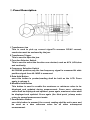
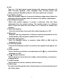
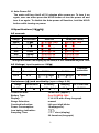
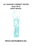
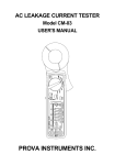
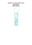
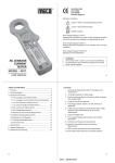
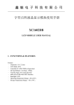
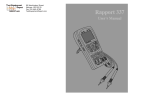
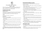
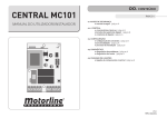
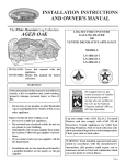
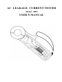
AC LEAKAGE CURRENT TESTER
Model 9809
USER’S MANUAL
TABLE OF CONTENTS
Ⅰ.Features…………………………………………………………………………1
Ⅱ.Panel Description………………………………………………………………2
Ⅲ.Operation lnstructions…………………………………………………………4
A.AC Leakage current Measurements………………………………………4
1.Leakage current Flowing into Ground Conductor……………………4
2.Out of Balance Leakage current…………………………………………5
3.Using the 50/60and Wide Selector………………………………………6
B.AC Load Current Measurement……………………………………………7
C.AC Voltage Measurements…………………………………………………7
D.Resistance and continuity Measurement…………………………………8
E. Relative Reading Measurements…………………………………………8
F. Holding the LCD Reading……………………………………………………8
G.Finding the MAX/MIN Value…………………………………………………8
H.Auto-Power-Off………………………………………………………………9
IV.Specifications……………………………………………………………………9
V. Battery Replacement…………………………………………………………10
Ⅰ.Features
1.Accurate AC digital clamp meter for leakage current measurement.
2.10μA high resolution on 40mA range.
3.Shield transformer jaws to minimizs the effect of external stray
magnetic field.
4.Large jaw with 30 mm diameter.
5.Five Ranges (40mA, 400mA,4A,40A,100A)for all application.
6.A filter circuit is designed to eliminate the effect of high frequency
noise and harmonics by setting the frequency selector switch at the
50/60 Hz position for AC current measurement.
7.Large 3 3/4 digits LCD
8.Fast bargraph display (20 times/sec.)for transient observation.
9.Continuity and frequency measurements.
10.Max/Min and Data Hold functions.
11.Relative Measurement.
12.600V overload protection for ohm measurement.
13.Easy single rotary switch for any function selection.
1
Ⅱ.Panel Description
1.Transformer Jaw
This is used to pick up current signal.To measure DC/AC current,
conductor must be enclosed by the jaw.
2.Transformer Trigger
This is used to open the jaw.
3.Function Selector Switch
This is used to select the function user desired, such as ACV ,ACA,ohm
and continuity.
4.Frequency Selection Switch
At 50/60Hz position,only the low frequency signal is measured.At wide
position,signal from 40-1KHZ is measured.
5.Data Hold Button
once this button is pushed,reading shall be held on the LCD. Press
again to release it.
6.Max/Min Hold Button
This button is used to enable the maximum or minimum value to be
displayed and updated during measurement. Press once, minimum
value shall be displayed and updated. press again, maximum value shall
be displayed and updated. Press again (the third push ),clamp meter
return to normal measurement mode.
7.Zero/Relative Button
once this button is pressed, the current reading shall be set to zero and
be used as a zero reference value for all other subsequent
measurement.
2
8.LCD
This is a 3 3/4 digit liquid crystal display with maximum indication off
3999. Function symbols, units, bargraph, sign, decimal points, low
battery symbols, Max/Min symbols, and zero symbol are included.
9.Low Battery Symbol
When this symbol appears, it means the battery voltage drops below the
minimum required voltage. Refer to Section V for battery replacement.
10.Zero/Relative Symbol
When this symbol appears, it means a reference value has been
subtracted from the actual reading. The reading shown is a offseted
value. Press and hold the zero button for 2 seconds to disable this
function.
11.Data Hold Symbol
Once the hold button is pressed, this symbol appears on LCD.
12.Bargraph
Bargraph has forty segments. It displays segments proportional to the
actual reading. Each segment represent one count.
13. Max/Min Hold symbol
Once the Max/Min button is pressed, either MAX or MIN shall be
displayed on LCD.
14.Continuity Symbol
If ohm and continuity function is selected, this symbol shall appears on
LCD.
15.Units symbols
Once a function is selected, corresponding unit (V,Ω, A,or Hz) shall be
displayed on LCD.
16.V Ω Hz input Terminal
This terminal is used as input for voltage, ohm/continuity, or frequency
measurements.
17.COM Terminal
This terminal is used as common reference input.
18.Hand strap
Put your hand through the hole of hand strap to avoid accidental drop of
the clamp meter.
3
Ⅲ. Operation Instructions
A. AC Leakage Current Measurements
WARNING: Make sure that all the test leads are disconnected from the
meter’s terminals for current measurement.
1. Leakage current Flowing into Ground conductor
4
a.Set the rotary switch at desired range.
b.Press the trigger to open the jaw and fully encloes the wire goes to
the ground. Make sure the two half jaws are properly closed.
c.Read the measured value from the LCD display.
2. Out of Balance Leakage current
5
a. Set the rotary switch at desired range
b.Press the trigger to open the jaw and fully enclose all two wires
(single phase, two wires), three wires(three phases, three wires), or four
wires(three phases, four wires).Make sure the two half jaws are
properly closed.
c.Read the measured value from the LCD display.
3. Using the 50/60 and wide Selector
50/60 position
This clamp meter has very good frequency response due to the electric
property of the transformer jaws used. Therefore, the measurement
result contains not only the fundamental frequency of 50/60Hz but also
the high frequencies and harmonics superimposed on the fundamental
frequency. To eliminate the effect of high frequency noise, a low pass
filter is designed to filter out high frequency signal. To enable the filter,
set the switch at the 50/60 position. The filter’s cut-off frequency is set
at 100Hz with an attenuation characteristic of approx. 24dB/octave.
Wide position
If the circuit under test is originated from a high frequency generating
device such as inverter, switching regulators, etc., then the switch
should be set at wide position to measure the signal which contains the
frequency from 40Hz-1kHz.
To make sure the presence of high frequency signal, set the switch at
50/60 and wide position to see the difference. If the reading is very
different, it is certain that the high frequency signals or harmonics
present.
6
B.AC Load Current Measurement
LOAD CURRENT
LEAKAGE CURRENT
a. Set the rotary switch at desired range.
b. Press the trigger to open the jaw and fully enclose only one wire. No air
gap is allowed between the two half jaws.
c. Read the measured value from the LCD display.
C.AC Voltage Measurements
WARNING: Maximum input for DC V is 600,and for AC V is 600. Do
not attempt to take any voltage measurement that exceeds the limits.
Exceeding the limits could cause electrical shock and damage to the
clamp meter.
7
a.Set the rotary switch at 400V
b.Insert the test leads into the input jack.
c.Connect the test prods of the test leads in PARALLEL to the circuit
to be measured.
d.Read the measured value from the LCD display.
WARNING: Before taking any in-circuit resistance measurement,
remove power from the circuit being tested and discharge all the
capacitors.
D. Resistance and Continuity Measurement
1. Set the rotary switch at Ω
2. Insert the test leads into the input jack.
3. Connect the test prods of the test leads to the two ends of the
resistor or circuit to be measured.
4. Read the measured value from the LCD display.
5. If the resistance is lower than 40Ω, a beeping sound shall be
heard.
E.Relative Reading Measurements
The zero button also can be used to make a relative measurement. Once
the button is pushed, the current reading is set to zero and a zero
symbol shall be displayed on LCD. All the subsequent measurement
shall be displayed as a relative value with respect to the value being
zeroed. press the zero button for 2 seconds to return to normal mode.
F.Holding the LCD Reading
Press the HOLD button, then the reading shall be hold and kept on LCD.
G.Finding the MAX/MIN Value
Press the MAX/MIN button to enable the maximum and minimum values
to be recorded and updated during measurement. Push the button once,
the maximum value shall be displayed and updated. Push again
(second push ), the minimum value shall be displayed. Push again(third
push), MAX/MIN function shall be disabled and return to the normal
measurement mode.
8
H. Auto-Power-Off
The meter will turn itself off 30 minutes after power-on. To turn it on
again, user can either press the HOLD button or turn the power off and
turn it on again. To disable the Auto-power-off function, hold the HOLD
button while turning on power.
IV.Specifications(23℃±5℃)
AC current:
Accuracy
Wide(400-1KHz)
Range
Resolution
50/60 Hz
40mA
400mA
10μA
100μA
±1.0%±0. 5mA
±3.0%±5.0mA
±4.5%±0. 5mA
±3.0%±5.0mA
4A
40A
1mA
10mA
±4.0%±0.1A
±4.0%±1.0A
±4.0%±0.1A
±4.0%±1.0A
80A
1
80-100A
100mA
100mA
±2.5%±1.0A
±5.0%±1.0A
±3.0%±1.5A
±5.0%±1.5A
1
Though the meter can display up to 400A,it is not calibrated beyond 100A
AC Voltage( input impedance:10MΩ)
Range
Resolution
50/60Hz
40-1KHz
400V
0.1V
±1.5%±2dgts
±2.0%±4dgts
Resistance (Ω) and continuity: (open voltage 0.4V)
Range
Resolution
Accuracy
Beeping
40-400Ω
0.1Ω
Conductor size:
Battery Type:
Display:
Range Selection:
Overload indication:
Power Consumption:
Low battery indication:
Sampling Time:
±1.0%±2dgts
<38.0Ω
Overload
protection
AC 600V
OL Protection
AC 600V
30mm max.(approx.)
One 9V NEDA 1604
3 3/4 LCD with 40seg. bargraph
manual
left most digit blinks
10mA(approx.)
2 times/sec.(display)
20 times/sec.(bargraph)
9
Operating Temperature:
Operating Humidity:
Storage Temperature:
Storage Humidity:
Dimension
Weight:
Accessories:
-10℃ to 50℃
less than 85% relative
-20℃ to 60℃
less than 75% relative
210mm(L)×62.0mm(W)×35.6mm(H)
8.3″(L) ×2.4″(W) ×1.4″(H)
200g(battery included)
Carrying bag×1
Users manual×1
9V NEDA 1604×1
V. Battery Replacement
When the low battery symbol is displayed on the LCD, replace the old
batteries with two new batteries.
A.Turn the power off and remove the test leads from the clamp meter
B.Remove the screw of the battery compartment.
C.Slide off the battery compartment.
D.Remove the old batteries.
E.Insert one 9V NEDA 1604 or G6F22 batteries.
F.Replace the battery compartment and secure the screw.
10