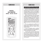
1
1 . Saf ety Inf or mation WARNING ඝ The following is important to use Rapport337 safely. First of all, read through "the precautions using the system. for your safety " before Make sure to check the input and output range of voltage or current at every input and output ports of Rapport337 before connecting each of them, so that the system cannot be overloaded when in use. Set up the range for measuring voltage, current and resistance for their known values and use the maximum range for unknown values to protect the unit from damage. 2 1 . Saf ety Inf or mation When the meter function is being used, do not connect any device to the VIDEO IN/OUT terminals at that time, as the grounding could cause any damage or trouble to both of them. The following operational environment should be maintained constantly for the proper use of Rapport337. 㯲 Temperature : -10 ~ 50 㯲 Relative humidity : 30% ~ 90% 㯲 Recharging voltage : 12V ·G10%, above 1A 3 WARNING ඝ Pay attention to the following precautions Rapport337. when using Do not use the unit in damp humidity or leaking gas environments. Do not touch it with wet hands. Be mindful not to shock or shake the unit while in use to avoid damage. Avoid the places of strong magnetism or electric wave, which would cause incorrect measuring. Be careful not to expose the ports or joints to dirt or liquid. Make sure to use specified replacement fuses described in the 3rd chapter. Do not disassemble the Rapport 337. Do not use the meter function, when the Rapport337 or the lead set look damaged. Do not measure resistance when the power is applied to a circuit. When using the meter function, do not forget to turn on the power of Rapport337 and set up the proper measurement mode before connecting to a circuit to be measured. Turn off the power to the circuit to be measured and discharge all high voltage capacitance before starting resistance or continuity tests to avoid damage to the Rapport 337. Put the finger behind the protecting pad when using a probe. 4 1 . Saf ety Inf or mation WARNING ඝ Battery Charging & Its Precautions UTP CABLE TEST AUX IN T R DC12V With the rechargeable 6 nickel hydrogen (Ni-MH) AA-size batteries placed in, Rapport337 can be charged with an adopter of above DC 12V, 1A, and it takes more than 8 hrs for the battery to be fully charged. The battery operates normally after initial 2 or 3 times of full charging, and it can be used for about 3 hrs and above. The battery charging can be checked on the initial picture of POWER ON, and also confirmed on the VIEW INFORMATION. The battery is recharged when connected to a DC adopter irrespective of the Power slide S/W or button. Alkaline battery(AA size) is usable for about 2 hrs. T R DC12V, 1A 5 - Cautions for Battery The following batteries can be used for Rapport337 - (AA)-size alkaline battery (6EA) - (AA)-size chargeable nickel hydrogen (Ni-MH) battery (6EA) Use only chargeable nickel hydrogen (Ni-MH) batteries, when charging batteries,using an adapter to Rapport337. Place the CHARGE SWITCH "ON" position for recharging. The CHARGE SWITCH is located on the upper part of battery insert. (Refer to the figure below) The performance of batteries can be very different, according to manufacturers. Please use any reliable brand. Do not mix batteries of different manufacturers when charging batteries. Make sure not to disorient the polarization of batteries. Do not short-circuit or disassemble batteries. Make sure to check the polarization and the voltage and current ratings before charging batteries and disconnect the charger immediately should an abnormal situation arise. 6 2 . Intr oduction of Rappor t3 3 7 FEATURES As a handy and portable device designed for testing various appliances, for the image-output equipments to be installed, Rapport337 is an efficient tester with useful testing functions, to assist the installation of CCTV, UTP test, communications test, RS-485 communications inspection, etc. For testing each function, set up modes and capacities to be tested, using the key pad located on the front part of Rapport337. Main Functions of RAPPORT337 Video tester ඖ The video signal and the quality of picture can be tested, and brightness, color and focus can also be adjusted while the image is being watched. ඖ Video signal generator mode : lt outputs color bar Red, Blue and Green screen to allow technician to inspect video monitor or DVR. Support both PAL & NTSC video signal format. Multimeter ඖ Voltage, current, resistance, short-test can be tested. PTZ Controller ඖ The basic operational test of PTZ, and other tests of focus and image checkup, etc. that are needed for the installation of PTZ are possible. It suppor ts RS-485/422 communications mode. UPT Cable tester ඖ The wiring condition(disconnected, shorted) of UTP cable can be checked out. 7 Standard Items Check the contents of your Rapport337 package with the standard checklist below placing them on a level place. Rapport337 Main Body User's Manual Test Lead Set(Red, Black) Adapter Rechargeable AA(Size) Nickel Hydrogen(Ni-MH) Battery (6EA) Necklace UTP test Terminal BNC Video Cable Car Power jack Optional Items 㯲Tester Bag 8 2 . Intr oduction of Rappor t3 3 7 ඝ Names & Functions of Each Part 2 3 1 4 PWR CHG Rx Tx 5 RAPPORT337 MODE SET OSD PWR BRIGHT CONTRAST FAR +TELE - AR D WI E NE 6 7 10A mA 10A MAX UN FUSED V/ 400mA MAX FUSED 9 MAX 400V DC 400V AC 500V MAX 8 Part ྙ Name Power LCD Function Red LED is on when the system is switched on Charge Indicating LED Data Transmitting LED Red LED is on when data is transmitted ྜ Data Receiving LED Red LED is on when data is received ྜྷ LCD ྚ ྛ ྞ Key Button MODE Button Green LED is on when being charged TFT LCD Controlling External Devices of Rapport337 Mode Select (Video, Multi Meter, PTZ Control, UTP Test) SET Button It is used when setup is changed OSD Button It toggles OSD & POWER on/off FAR Button It adjusts PTZ focus (far direction) & Video Mode Brightness NEAR Button It adjusts PTZ focus (near direction) & Video Mode Brightness TELE Button It zooms PTZ(zoom in) & adjusts Video Mode Contrast WIDE Button It zooms PTZ(zoom out) & adjusts Video Mode Contrast Shift Setup Button It shifts up, down, right, left for PTZ & for menus & others 10 2 . Intr oduction of Rappor t3 3 7 Part Name ྟ Key Button Function METER PART Resistance Button It measures resistance Voltage Button It measures voltage Setup Change Button IT changes setup of AC/DC, resistance/continuity test Current Measuring Button 1 Current Measuring Button 2 Current Measuring Button 3 HOLD, HELP Button ྠ Test Lead Connection It is used for measuring lower current below 4 mA It is used for measuring current below 400 mA It is used for measuring current below 10A Measuring range can be changed and holded HELP function Test Lead Positioning for Lead Connection It indicates position of Red Test Lead for measuring Voltage & Registance It indicates position of Black Test Lead It indicates position of Red Test Lead for measuring Current below 400mA It indicates position of Red Test Lead for measuring Current below 10A 11 1 2 3 4 6 5 Part Name Function ྙ Input BNC It inputs external image signal ྚ Output BNC ྛ Communication Port It outpus input image signal to Rapport337 or internally generated Video Test Signals It is the port of input & output of communication signal.(Rx+, Rx-,Tx+,Tx-) ྜ Base It braces Rapport337 ྜྷ Safety hook Up It hangs on the neck for safety ྞ Safety hook Down It hangs on the neck for safety 12 2 . Intr oduction of Rappor t3 3 7 1 2 3 4 Part Name Function ྙ UTP Jack Test jack for UTP cable ྚ AUX Jack Audio, AUX input port (function to be added when upgraded) ྛ DC Power Jack ྜ Power S/W DC power input jack(for over DC12V,1A) ON/Off main power supply 13 3 . Specif ications of Rappor t3 3 7 ඝ General Specifications 12V · 10%, above 1A Input Voltage Electric Characteristic Battery Chargeable Ni-MH battery 6EA (AA size) Charging Time Above 8 hrs Operation time More than 3 hrs Built-in Charger TV Type NTSC/PAL Image level 1 Vpp, 140IRE Image Protocol PTZ operation test UTP Cable Test Size Multi-Protocol support Transmission speed Transmission mode Kinds of test 2400bps ~ 38400bps RS-422,RS-485 direct/cross cable, and broken or short-circuit can be tested W(88mm) X L(190mm) X T(58mm max) 14 3 . Specif ications of Rappor t3 3 7 ඝ Meter Specifications Measuring Item Measured Value Minimum Measuring Accuracy 400mV 100uV · (0.8% + 2dgts) 4V 1mV 4V 10mV 400V 100mV 4V 1mV 40V 10mV 400V 100mV DC Voltage AC Voltage 400uA 0.2uA 4mA 2uA 40mA 20uA 400mA 200uA 10A 2mA 4mV DC Current 400mV 10A · (1.0% + 2dgts) · (1.2% + 3dgts) (40H ¡G~ 500H ¡) · (1.0% + 2dgts) · (1.5% + 2dgts) 15 · (2.0% + 3dgts) Measuring Item Minimum Measuring Accuracy 400uA 0.2uV 4mA 2uV · (1.5% + 5dgts) (40Hz ~ 500Hz) 40Hz ~ 500Hz 40mA 20uV 400mA 200uV 10A 2mV · (3.0% + 4dgts) 40Hz ~ 500Hz 400 ˟ 0.1 ˟ · (1.0% + 4dgts) 4༮ 1˟ 40༮ 10˟ 400 ༮ 100 ˟ 4༯ 1༮ · (2.0% + 4dgts) 40༯ 10༮ · (3.0% + 5dgts) Measured Value 4mV AC Current 400mV 10A · (1.8% + 5dgts) (40Hz ~ 500Hz) 40Hz ~ 500Hz · (1.0% + 2dgts) Resistance Continuity Rated fuse Beeper is activated when the resistance is below 80 250 Volt 800 mA 16 ˟ 4 . Functional Use ඝ Power ON/OFF The Power slide switch is located on the side of Rapport337. Turn the Power slide switch on, and press to start the Rappor337. To turn off the system, press more than 3 sec. Then, POWER OFF is displayed on the main screen with a beep. Release the button. The power goes off. A rechargeable battery should be plugged in over 8 hrs for full charge. The charged battery can operate for 3 hrs or so. When the battery indicator shows below [][], recharge it for use. (Full charge : [][][][]) ඝ OSD Setup Screen when Power is on When power is on, the setup OSD is displayed, and it enters automatically to the video test mode after 3 ~ 5 sec. The initial OSD displays its RAPPORT337 version and the initial setup on the screen. Product Version : 2.02 Firmware Version : 2.03 Initial Protocol : PELCO-D TV mode : NTSC/PAL automatic setup Battery indicator : [][][][] RAPPORT : User's name(Name can be changed in Main menu.) Model & software versions are subject to be changed without any further notice. 17 ඝ Mode Setup LCD Screen is changed in order of VIDEO 㲯 METER whenever MODE SELECT window displays on LCD screen when pressed more than 3 sec. Press 㲯 PTZ 㲯 UTP key is pressed once. key is key after selecting the mode you want, using the shift setup key. Video Tester Mode : At this mode, the image quality of the external input picture signal is tested, or the monitor, etc. is tested by using the picture signal that is output from PATTERN GENERATOR mode. Digital Multimeter mode : At this mode, voltage, current, & continuity are tested. PTZ Controller mode : At this mode, the basic movement of up, down, right, left for PTZ is made, and zooming & manual focus are adjusted. UTP Cable Tester mode : UTP cable, direct & cross cable, disconnection, and short circuit are tested. 18 4 . Functional Use View Information mode : At this mode, the basic information of RAPPORT337 can be seen. (version, battery residual, communications protocol, & speed.) Main Setting mode : At this mode, the basic setup of RAPPORT337 can be changed. (user's name, auto power off time, beeper, brightness, contrast, etc.) HELP : HELP image relevant to the mode displays when the key is pressed on for more than 2 sec. at each mode. How to use each mode is explained at each HELP menu. ඝ VIDEO TESTER Connect the output terminal of video output system to the video input BNC of RAPPORT337. Connect the video output BNC of RAPPORT337 to the video input terminal of system. 19 OSD Screen Setup VIDEO : Indicates that the system is in video test mode. NTSC : Indicates if input or output video signal system is NTSC or PAL. Input video signal is output on LCD screen by automatic checking without a special setup key, and output video signal system in Pattern Generator mode can be switched to NTSC or PAL, using B[][][][] or key. : Indicates screen brightness, and the brightness increases gradually by +1 when key is pressed, and decreases gradually by -1 when key is pressed. And it returns to the initial setup value when one of the two keys is pressed for more than 3 sec. C [][][][] : Indicates screen sharpness, and the brightness increases gradually by +1 when key is pressed, and decreases gradually by -1 when key is pressed. And it returns to the initial setup value when one of the two keys is pressed for more than 3 sec. 20 4 . Functional Use Enter the PATTERN GENERATION MODE when key is pressed in VIDEO mode. Output video system is changed to NTSC or PAL, using or key. Output pattern can be seen COLOR BAR, RED, BLUE, GREEN or its reverse order, using COLOR BAR Press RED key as PATTERN or BLUE key. GREEN GENERATION MODE. 21 MODE returns to Video ඝ DIGITAL MULTI METER Voltage, current, resistance, continuity can be tested. WARNING To prevent an electric shock, injury or damage to RAPPORT337, cut off the power supply of the circuit, and discharge all the high-voltage capacity before testing resistance and continuity. When applying the meter function by using your RAPPORT337, make sure to turn on its power and set up the proper mode before connecting the test lead set to the circuit to be tested. 㯲SETUP of KEY SELECT First, press button, and then press button to be changed to OHM/BUZZ First, press button, and then press button to be changed to ACV/DCV. This button is used to test current below 4mA. This button is used to test current below 400mA. This button is used to test current below 10A. 22 4 . Functional Use Description of METER MODE LCD WINDOW Part Function Description ྙ Kinds of test to set up ྚ Test value to display - ˟ unit of resistance test is indicated - Indicator of AC or DC value of voltage or current - AC voltage & current are indicated as rms (root mean square) ྛ Measured value graph - Input measured value is indicated in the form of graph 㯲Graph is changed automatically equal to the measured value in automatic mode 㯲OVER is displayed when higher value is measured than the setup value ྜ Measured value in hold The measured value is stored and indicated here, when SET key is pressed at the moment of the value measured ྜྷ MODE display - Resistance test - Continuity test - Set up tests of DC/AC voltage, current Digital Multi Meter Mode is displayed 23 Part ྞ Function Description DC DC Voltage test AC AC Voltage test OHM VOLT AMP Resistance test (Measuring unit : ˟ ) Voltage test (Measuring unit : V) Current test (Measuring unit : mA, A) Continuity test (Starting to beep at below 80 ˟ ) MEASURING RESISTANCE The unit of resistance is ˟ . The meter sends low current into the circuit so that resistance can be measured. This current runs all the paths between probes, and the measured resistance value is all values added among them. How to measure : Connect the red lead to and the black lead to , as shown in the figure above at left. and measure the resistance directly at the resistance measuring mode, by pressing on the key pad. 24 4 . Functional Use 㯲TESTING CONTINUITY Continuity means the presence of a complete path for current to flow. And the continuity test features a beep that sounds when a circuit is complete. The beep allows users to quickly test continuity without having to watch the display. How to test : The resistance mode returns to the continuity mode, when is pressed. The beeper is activated when the resistance between the red probe and black probe is below 80 ˟ . 25 MEASURING AC & DC VOLTAGE Voltage means the difference in electrical potential between two points. The polarity of AC voltage varies over time, while the polarity of DC is constant over time. The meter displays ac voltage values as rms (root mean square readings. The rms value means the equivalent dc voltage that can produce the same amount of heat in a resistance as the measured sinewave voltage. How to measure : First, press select AC or DC by pressing , the voltage measuring button, and then In case of DC to be measured, place the red lead on + point, and the black lead on - point, each on the voltage source 26 . 4 . Functional Use MEASURING AC & DC CURRENT Current is simply defined as a flow of electrons running through a conductor. To measure current, you must break the circuit under test, and then place the meter in series with the circuit. The current measuring range of the meter is 10A max. How to measure : First, turn off the power of the circuit, and, discharge the high voltage capacitor. Fix the red lead into the terminals of mA and 10A in accordance with the value to be measured. Select one of the buttons & . When & are selected, place the red lead on mA, and When GGGGGGGGGG GGGGG button is selected, place the red lead on 10A. 27 WARNING Check for the location of the test lead set at current test mode. Place the red lead at mA only for below 400mA, and place it at 10A when the value to be tested is over 400mA, or the value is unknown. WARNING Use it only for the current measuring after checking for the test mode. Especially, after the current mode is selected, there may occur burnout of fuses, damage, or breakdown of the system when the voltage is measured. 28 4 . Functional Use ඝ PTZ CONTROLLER How to connect each terminal and LCD screen PTZ Operation Test : The basic operation of PTZ : Up, Down, Left, Right, and Zoom, and Manual focus controlling are possible, also. The test of various protocols and transmission speed are possible. In order to control PTZ, connect the PTZ communications cables to T X terminal of RAPPORT337. - PTZ Control Setup Screen ADD Setup Screen Protocol Setup Screen 29 Communications Speed Setup Screen - Key Board Control Code Screen - The controlling code of protocol from the key board or DVR is displayed on the screen. Most important, however, is that the communications speed should be of one accord. When you want to know the input signal of an exterior controller, you can see the input data by connecting the communications cable to the RX terminal of the Rapport 337. 㯲How To Control PTZ PTZ functions (controlling Up, Down, Left, Right), etc. are possible to be tested, by using buttons : FAR/NEAR(FOCUS ADJUSTING), TELE/ WIDE(ZOOM ADJUSTING), and SHIFT SETUP. 㯲FUNCTION SETUP of PTZ By using the SHIFT SETUP key, adjust GPST / SPST / TOUR / SPD / MENU displayed on the lower part of LCD screen by pressing SET key once shortly. GPST : It moves the camera view to the designated preset location. Setup can be from 1 up to 99. (short for GO TO PRESET). When the cursor runs to GPST position after key is pressed, select the previously memorized PRESET number, using number, using & keys. When the selection is completed, press key one more time, it moves to the memorized location. 30 4 . Functional Use SPST : It memorizes PRESET. Setup can range from 1 up to 99. (short for SET PRESET). First, move the camera to the view to be designated , and press key, and using & keys, place the cursor at the location of SPST. Then, set up the address that you want to memorize by using & keys, and then, press key one more time. The information of location is stored in SPST adress. TOUR : It operates TOUR set up at SPST and MENU. Setup can be from 1 up to 99. TOUR can be designated in the MENU of PTZ. SPD : Place the cursor at the location of SPD, applying the procedures described above. Total 16 steps(from 1 to 16) of speed are available to be selected using & keys. MENU : Place the cursor at the location of MENU, applying the procedures described above. The MENU of PTZ itself is available to be displayed on LCD screen. using key. CAUTION 㯲Make sure to check for communications protocol, transmission speed, and ID. 31 CONTROL SETUP of PTZ PTZ ADDR is activated on the upper part on LCD screen, when key is pressed more than 3 sec, and, the activated menu can be changed to ROTOCOL , BAUDRATE by pressing & keys. PTZ ADDR : Setup of PTZ ID. The initial setup is made 001, and changing ID of PTZ is done by pressing & keys. The setup is available up to 255 max. PROTOCOL : Setup of PTZ PROTOCOL The initial setup made PELCO-D, and changing to PELCO-D, PELCO-P, and WONWOO are available, in accordance with the protocol mode of PTZ. It is done by pressing & keys. 32 4 . Functional Use * BAUDRATE : Setup of TRANSMISSION SPEED The initial setup is 2.4KBps, it can be made up to 2.4Kbps ~ 38.4Kbps. It is done by pressing To escape from PTZ CONTROL again. & keys. SETUP Mode, simply, press the key CAUTION Make sure to check for CAMERA ID, PROTOCOL, BAUDRATE when the test is carried. PTZ operation test can not be done when the setup is different. 33 ඝ UTP CABLE TESTER 㯲 Connect UTP cable to be tested to UTP port of RAPPORT337, connect the other end to UTP tester. The connected condition of the cable can be checked, by pressing key, after the connection is completed. Direct cable and cross cable can be classified, and disconnection or short-circuit can be also examined. Cross cable Short-circuit & Disconnection DIRECT Direct cable 34 while 4 . Functional Use ඝ VIEW INFORMATION Mode Setup : First, press key more than 3 sec. and select VIEW INFORMATION on MODE SELECT MENU, then press key. ඝ MAIN SETTING Mode Setup : First, press key more than 3 sec. and select MAIN SETTING on MODE SELECT MENU, then press key. 㳕 Select the item by pressing & changed by pressing keys. & keys. The each setup value can be A user can put the name he or she wants at USER NAME by editing. At SLEEP TIME, power goss OFF automatically, if the button is not pushed down for a fixed time. 35 T ABLE OF CONTENTS Before Reading the User's Manual 1 1. Safety Information 2 WARNING 2. Introduction of Rapport337 Names & Functions of Each Part 3. Specifications of Rapport337 2 7 9 14 General Specifications 14 Meter Specifications 15 4. Functional Use 17 Power ON/OFF 17 OSD Setup Screen when Power is on 17 Mode Setup 18 VIDEO TESTER 19 DIGITAL MULTI METER 22 PTZ CONTROLLER 29 UTP CABLE TESTER 34 VIEW INFORMATION 35 MAIN SETTING 35 Distributed by: Manufacturer : Wonwoo Engineering Co., Ltd. www.goodome.com Made in Korea MEMO B ef or e Reading the User Õs Manual WARNING Make sure to read through "Safety Information" Rapport337. before using This basic instruction manual is for users of Rapport337. Starting with the outline of Rapport337, the manual is emphasized on the explanations of its operation, how to be connected to the other devices, how to use every button, and how to set up the system. It is highly recommended, for those who have handled similar devices as well as for those who are using it for the first time, to read every description line by line, especially cautions, before using the Rapport 337. And when there is any question when in use or there is any damage, make sure to contact the dealer of your Rapport337. In the 1st Chapter "Safety Information" , warnings and precautions are explained for the safety of users when Rapport337 is in use. In the 2nd Chapter "Introduction and appearance are explained. of Rapport337" , its features In the 3rd Chapter "Specifications of Rappor t337" , the specification of the rapport337 components are explained. In the 4th Chapter "Functional Use" , the functions of Rapport337 are explained so that the users can use it conveniently. 1