1
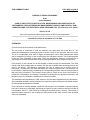
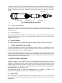
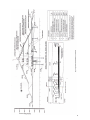
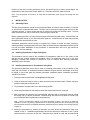
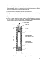
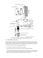
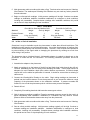
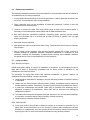
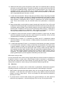
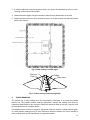
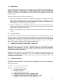
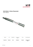
FORMAT FOR SENDING COMMENTS
Last Date for Comment is 31 December 2009
E-Mail ID for sending comments: [email protected]
Document No.: Doc WRD 16 (504)C
Title: CODE OF PRACTICE FOR INSTALLATION, MAINTENANCE AND OBSERVATION OF
INSTRUMENTS FOR PORE PRESSURE MEASUREMENT IN EARTH AND ROCKFILL DAM –
VIBRATING WIRE TYPE ELECTRICAL PORE PRESSURE CELL (First Revision of IS 12949)
Organization/ Individual:
Sl.
No.
Clause/
Sub-clause
Paragraph
Figure/Table
Type Of
Comment
(General/
Technical/
Editorial)
Comments
(Justification For Change)
Proposed Change
1.
2.
3.
4.
1
FOR COMMENTS ONLY
DOC: WRD 16 (504) C
OCTOBER 2008
BUREAU OF INDIAN STANDARDS
Draft
Indian Standard
CODE OF PRACTICE FOR INSTALLATION, MAINTENANCE AND OBSERVATION OF
INSTRUMENTS FOR PORE PRESSURE MEASUREMENT IN EARTH AND ROCKFILL DAM –
VIBRATING WIRE TYPE ELECTRICAL PORE PRESSURE CELL (First Revision of IS 12949)
ICS No. 93.160
(Not to be reproduced without the permission of BIS or used as standard)
----------------------------------------------------------------------------------------------------------------------------------Last date for receipt of comments is 31-12-2009
----------------------------------------------------------------------------------------------------------------------------------FOREWORD
(Formal clauses of the foreword will be added later)
The soil mass is composed of solid soil particles and voids filled with water and air. The
constructed embankment will always contain a certain volume of air and water within the voids.
The air is compressible while water is highly incompressible. Hence when embankment settles
due to compaction by rolling, or due to self-weight, the void space contract. This causes pressure
in the pore fluid comprising air and water. Thus, the intergranular pressure is reduced due to
opposing pore pressure and therefore the shear strength depends upon intergranular pressure.
Pore pressure is also caused due to the seepage of water through an embankment. The initial
energy head of percolating water at entrance into the dam is greater than the-energy heat at any
point in the interior. The difference represents the loss of energy due to friction forces of
percolation. The potential of the water decreases as it seeps through the dam. Pore pressure due
to percolation is determined by subtracting the corresponding elevation from the flow potential at
that point being considered. Thus pressure at any point in a dam at any time is the function of
compaction, consolidation and seepage. Procedures for testing the pore pressure cells both in the
laboratory and in the field before installation are under formulation.
This standard was first published in 1990; however, the Committee responsible for the formulation
of this standard decided to revise it based on the experience gained during the last decade as well
as technological development in the field.
For the purpose of deciding whether a particular requirement of this standard is complied with the
final value, observed or calculated, expressing the result of a test or analysis, shall be rounded off
in accordance with IS 2 : 1960 ‘Rules for rounding off numerical values ( revised)‘. The number of
significant places retained in the rounded off value should be the same as that of the specified
value in this standard.
2
TABLE OF CONTENTS
0. FOREWORD
1. SCOPE
2. VIBRATING WIRE PIEZOMETERS
2.1 OPERATING PRINCIPLES
2.2 ACCESSORIES
2.2.1 HOUSING
2.2.2 THERMISTOR
2.3 CABLE
2.4 CABLE IDENTIFICATION TAGS
2.5 JUNCTION CUM SWITCH BOX
2.6 CABLE SPLICING KIT
2.7 READ-OUT INDICATOR
3. TYPICAL INSTRUMENTATION SCHEME
4. VERIFICATION AND CALIBRATION
4.1 BOIL THE FILTER
4.2 REASSEMBLE THE PIEZOMETER
4.3 QUICK ZERO CHECK
4.4 DOWNHOLE PRESSURE CHECK
5. INSTALLATION
5.1 SATURATING FILTER
5.2 INSTALLING PIEZOMETERS USING SAND
5.3 INSTALLING PIEZOMETERS IN FOUNDATIONS USING SAND
5.4 GROUTED BOREHOLE INSTALLATION
5.5 IN-SITU OR PUSH IN INSTALLATION
5.6 EMBANKMENT INSTALLATION
5.7 LAYING OF CABLES
5.7.1 GENERAL PRECAUTIONS
5.7.2 CABLE TRENCHES
5.7.3 VERTICAL ROUTING
5.8 CABLE CARE
6. TAKING READINGS
6.1 INITIAL READINGS
6.2 TAKING OF READINGS
7. CONVERTING FREQUENCY INTO PRESSURE
7.1 TRANSDUCER CONSTANT
7.2 PRESENTATION OF DATA
8. TEMPERATURE CORRECTION
3
1.
SCOPE
This standard covers details of installation, maintenance and observation of Vibrating Wire type
pore water pressure cells for earth and rock-fill dams.
2.
VIBRATING WIRE PIEZOMETERS
2.1
Operating Principle
The vibrating-wire piezometer contains a magnetic, high-tensile-strength stretched wire, one end
of which is anchored and the other end fixed to a diaphragm. The diaphragm deflects in response
to applied pore water pressure, changing the tension in the wire and its resonant frequency.
Calibration of the piezometer establishes the relationship between pore water pressure and
resonance frequency.
To operate the piezometer, the wire is plucked by sending a broadband signal down the
piezometer cable to a coil magnet assembly beside the wire. When the plucking signal is turned
off, the wire continues to vibrate at its resonance frequency, which induces an alternating current
in the coil magnet. This signal can be read at the other end of the cable and then converted to
units of pressure.
The relationship between wire tension and resonant frequency is given by the following equation:
f = [σg / ρ]1/2/ 2L Hz
where f
σ
g
ρ
L
=
=
=
=
=
resonant frequency of wire in Hertz
tension of wire in kg/cm2
980 cm/sec2
density of wire in kg/cm3
length of wire in cm
The resonant frequency is directly proportional to the square root of wire tension and inversely
proportional to the length of the wire.
2.2
Accessories
2.2.1 Housing
For application in dams, the above mechanism is sealed in heavy duty stainless steel housing,
preferably with vacuum or inert gas inside it to prevent the corrosion of wire.
2.2.2 Thermistor
A thermistor should be incorporated in the sensor for temperature sensing and if necessary, to
make the temperature correction in the zero reading.
2.3
Cable
Cable used should be suitably protected to prevent water seepage through it. Cables may be
terminated in an intermediate junction cum switch box or directly routed to the observation room.
A typical vibrating wire piezometer is shown in figure 1.
2.4
Cable Identification Tags
After connecting cable to pore pressure cell the free end of cable should be marked or identified
with a permanent tag. A minimum of 3 tags should be used in the cable which should be placed at
4
a maximum spacing of 10 m over the entire exposed length of cable with non-corrosive material or
plastic tags engraved or embossed with appropriate transducer numbers. Permanent identification
should be used to prevent errors in identifying pore water pressure cells and their connecting
cables.
4-Core cable
Piezometer
Cable housing
Cable gland
Fig. 1 Typical vibrating wire piezometer
2.5
Junction Cum Switch Box
Multi position junction cum switch box suitable for connecting and switching inputs from group of
sensors to the readout unit should be provided. It should be water proof and made of nonmagnetic material.
2.6
Cable Splicing Kit
Cable jointing should be avoided to the extent possible. In case, it becomes necessary cable
slicing kit should be used to make a water resistant sealed joint between two cable ends properly
gripping the armouring.
2.7
Read-out Indicator
The read-out unit should be portable and suitable for reading all types of vibrating wire sensors.
3.
TYPICAL INSTRUMENTATION SCHEME
A typical instrumentation scheme of an earth dam is shown in Figure 2. The cables have been
routed to the downstream side in temporary observation rooms and will be connected later on to a
central data acquisition system on the top of the dam.
Note1: The arrangement shown for cable routing in figure 2 is typical for an earth fill dam and is not to be
universally used. Various methods of cable routing are used depending upon the location, size and the
design of the dam. The designers and the consultants are the best people to determine the layout for cable
routing from the sensors to the observation room.
4. VERIFICATION AND CALIBRATION
The main purpose of a verification test is to provide reasonable assurance that a sensor is
functioning properly. Unless there is access to sophisticated test facilities and calibration
equipment, acceptance tests may not be expected to achieve the accuracy and precision of the
calibration data provided on the sensor calibration record. Thus during evaluation of the results of
an acceptance test, look for obvious non-conformance rather than an exact match between the
data and the data on the calibration record.
Each piezometer should be verified and calibrated before it is installed in the dam or its
foundations. The following procedure should be followed for this purpose:
4.1
Boil The Filter
Remove the filter from the piezometer and boil it in a large vessel for at least 15 minutes, so that
its air goes out and it gets saturated with water. Allow the water to cool down to the room
temperature.
5
6
4.2
Re-assemble the Piezometer
Dip piezometer inside the boiled water and reassemble filter. Ensure water enclosed between
diaphragm and filter does not leak out of sensor when it is tilted or turned around.
4.3
Quick Zero Check
Ideally, this test should be conducted in a draft-free room where the piezometer can be kept at a
constant temperature. At minimum, the piezometer should be placed in a location that is out of
direct sunlight and allowed to reach thermal equilibrium with the surface it is resting on and the
surrounding air. This may take an hour. The piezometer should not be handled during this time or
during the test.
Connect the signal cable to readout and obtain a frequency reading. Readings should be checked
and ensured for their repeatability. Apply calibration factors to convert the frequency to a pressure
reading in Pa.
If the local elevation is above sea level, the pressure reading that obtained will most likely be
negative because the sensor calibration is referenced to one standard atmosphere (sea level). To
calculate an approximate correction for elevation, allow 0.1 kPa for every 10 meter of elevation
above sea level. Add the correction to the reading.
Note: For example, if the elevation is 1,000 meters, add a correction of 10 kPa to the pressure reading.
The working of piezometer may be considered satisfactorily if the difference between the corrected
pressure and zero is within 2 percent of the full scale of the piezometer (2 MPa for a 100 MPa
piezometer). To make a more precise check, corrections should be done for the true altitude, the
barometric pressure, and the temperature.
4.4
Down Hole Pressure Check
This test is conducted in a water-filled borehole or standpipe piezometer. Sensor calibration record
is required for this test.
Mark signal cable at two depths, one at a shallow depth and the other as deep as possible (within
the range of the piezometer). Measure from the location of the diaphragm: 23 mm (0.9 inch) from
the tip of the borehole piezometer; 112 mm (4.4 inches) from the tip of the push-in piezometer, and
51 mm (2 inches) from the tip of the embankment piezometer. Pull the filter off the piezometer, fill
it with clean water, and replace the filter. Hold the filter end up until the piezometer is placed in the
water.
Lower the piezometer to the shallowest mark on the signal cable. Clamp the cable in position and
wait at least 30 minutes for the piezometer to adjust to the temperature of the water. Connect the
piezometer signal cable to the readout device. Readings should be checked and ensured for their
repeatability. Record the frequency reading and the temperature reading at the shallow depth.
Lower the piezometer until the other mark on the signal cable is lined up with the same reference
used for the shallow position. Allow the piezometer to adjust to temperature at that depth.
Readings should be checked and ensured for their repeatability. Then record the frequency
reading, and the temperature reading. Convert both readings to units of pressure by applying
calibration factors. Subtract the shallow pressure from the deep pressure.
Note – It is done to avoid having to correcting for altitude.
Convert both pressure values to feet or meters of liquid head and compare to the distance
between the two marks made on the signal cable. There are many variables that can degrade the
7
accuracy of this test, including positioning errors, the specific gravity of water at each depth, the
temperature of the piezometer at each depth, etc. Correction should be made for these.
Note - The real purpose of the test is to verify that the piezometer gives roughly the reading that was
expected.
5.
INSTALLATION
5.1
Saturating Filters
The filter from piezometer should be removed and soaked or boiled in water for about 15 minutes
or until the filter is saturated with water. The filter can be removed by opening the locking nut with
a spanner wrench. In some models the filter is removed by pulling out the filter holder. In some
other models the filter can be removed by unscrewing the conical tip.
Before replacing the filter, the end of the piezometer should be filled with water. With the filter end
of the piezometer facing up, the filter should be replaced. A small amount of water may squeeze
through the filter stone as this is done.
Assembled piezometer should quickly be inserted into a bottle or bucket off water, keeping it
submerged while it is transported to the field. Water enclosed between diaphragm and filter should
not leak out before installation of the piezometer. A saturated filter with no air gap should be
ensured for accurate readings.
5.2
Installing Piezometers in Open Standpipes
This procedure may be used for the installation of piezometers, which are in the vicinity of the
dam-site but are located outside the foundation area. For monitoring water level in an open
standpipe, sufficient time should be allowed for level to stabilize after lowering piezometer
assembly into the borehole.
5.3
Installing Piezometers in Foundations Using Sand
The procedure described herein can be used for installing piezometers in the foundation of the
earth and rock-fill dam. A traditional borehole installation requires that the total depth of the hole
be drilled to one meter past the planned piezometer installation depth. Installation procedure
should be as follows:
1. Flush the borehole with water or biodegradable drilling mud.
2. Create a sand zone using a tremie to drop wet sand to the borehole bottom. Elevate casing to
maintain casing above the sand level.
3. Tie piezometer to signal cable in the filter-end-up position.
4. Lower the piezometer into the borehole when the desired sand level is achieved.
5. After piezometer is lowered to the desired depth, add sand with a tremie and continue pulling
the casing until it is above piezometer. Continue filling with sand until at least six inches (150
mm) of sand has been layered above the piezometer.
Note – There is an alternative method to the steps described in steps 4 and 5 and i.e called bag
installation. It is done by placing a piezometer into a canvas bag filled with sand and lowering the bag
into the borehole is also an acceptable piezometer placement technique (similar to the technique shown
in figure 3).
6. Isolate the piezometer by creating a bentonite clay seal above the piezometer sand zone
created in step 5. Installation specifications should be referred for thickness of seal. Typical
seal thickness is a minimum of one foot. Bentonite chips should be used and the seal should
8
be created slowly to ensure that no disturbance takes place in the piezometer placement.
Continue to pull casing up to complete this step.
Bentonite Setup Time: Maintain a water-filled borehole while the bentonite sets up. Typical
time for the bentonite chips to set up and form a seal is two-to-three hours. Bentonite supplier’s
directions should be consulted for recommended time intervals.
7. Completely fill remaining borehole with bentonite-cement grout mixture.
8. Mark piezometer cable at surface with stake or flag. Terminate wires and connect to VibratingWire Readout. If the Vibrating Wire Readout is weatherproof it may not need any further
protection from the elements.
9. Begin to collect periodic readings. Initial pressure readings typically will be high.
10. Continue to evaluate readings as installation stabilizes. Installation stabilization is contingent
on local conditions, including soil permeability. Complete datum readings after installation
stabilizes; this period can be hours or days depending on local conditions.
Tie string
Open top
50
Sensor cable
Tie wire
Bronze metal screen
Length varies
Water saturated
clean sand (2-4 mm)
Vibrating wire
Pore pressure cell
50
Cloth bag
Tie wire
70
All dimensions in millimetres.
Fig. 3 Piezometer cable assembly before installation
9
Piezometer cables 12 mm apart
Trench
To terminal well
Hole for
Foundation type tip
Offset trench
12 min.
Compacted
earth fill
300
Length varies
50 min.
300 500
Grout
(cement : sand = 1:3)
75 min.
Place embankment
tips in offset trench
900 max.
Main trench
450 min.
Offset trench
450-900
75 min.
600-900
Sellected fine material
Bentonite plug
Cables
Pore pressure cell assembly
Clean saturated sand
Ø100 min. drill hole
All dimensions in millimetres.
Fig. 4 Typical installation of piezometer in foundation of dam
5.4
Grouted Borehole Installation
Certain situations may require the boreholes to be grouted after the installation of the piezometers.
A grouted borehole installation requires that the total depth of the hole be drilled to one meter past
the planned piezometer installation depth. The following installtion procedure should be followed:
1. Flush the borehole with water or biodegradable drilling mud.
2. Tie piezometer to signal cable in the filter-end-up orientation.
3. Lower piezometer into borehole. Add additional weight (sand bag) if necessary.
4. Completely fill remaining borehole with bentonite-cement grout mixture. The requirement of the
grout mix is that it should have the same stiffness as the surrounding ground. For guidance
typical mixes for hard and medium soils and soft soils are given in Table 1.
10
5. Mark piezometer cable at surface with stake or flag. Terminate wires and connect to VibratingWire Readout. The weatherproof Vibrating Wire Readout may not need any further protection
from the elements.
6. Begin to collect periodic readings. Initial pressure readings will be high. Continue to evaluate
readings as installation stabilizes. Installation stabilization is contingent on local conditions,
including soil permeability. Complete datum readings after installation stabilizes; this period
can be hours or days depending on local conditions.
Table 1. Grout Mixes
Grout Mix for Hard and Medium Soils
Grout Mix for Soft Soils
Materials
Weight
Ratio by Weight
Weight
Ratio by Weight
Portland Cement
43 kg
1
43 kg
1
Bentonite
11 kg (as required)
0.3
18 kg (as required)
0.4
Water
114 liters
2.5
283 liters
6.6
5.5
In Situ or Push-In Installation
Sometimes it may be desirable to push the piezometers in rather than drill and install them. This
installation method requires a cone-head piezometer. It provides the advantage of readings from
an instrument placed directly into the native formation. However, it also requires extra precaution
to prevent twisting of the signal cable or damaging the piezometer by exerting too much force
while driving it into position.
The piezometer has a right-hand thread. A disposable adapter is needed to thread onto to the
piezometer to make the drill rod connection. The following installation procedure should be
followed:
1. Assemble the adapter to the piezometer.
2. Attach a coupling pin to the bottom of the drill rod and feed signal cable through the drill rod.
Continue assembling the drill rod string while threading the cable. Cable length should be
adequate for total installation depth plus surface distance requirements. If borehole depth
requires drill rod be added as piezometer is lowered, it should be ensured that no twisting of
cable occurs.
3. Connect the Vibrating-Wire Readout to the cable. Begin taking readings as piezometer is
pushed into the borehole bottom. Ensure that pressures do not exceed the maximum range
(capacity) of the piezometer shown on the calibration certificate. If pressure exceeds this
maximum, slow or halt the piezometer push-in until the excess pressure dissipates.
4. Detach drill rod.
5. Completely fill remaining borehole with bentonite-cement grout mixture.
6. Wait for pressure readings to stabilize. Excessive porewater pressure caused by the push-in is
typical immediately after installation. Installation of a bentonite cap may cause a reverse
pressure effect as the bentonite draws water away from the piezometer.
7. Mark piezometer cable at surface with stake or flag. Terminate wires and connect to VibratingWire Readout.
8. Start to collect periodic readings. Initial pressure readings typically will be high. Continue to
evaluate readings as installation stabilizes. Installation stabilization is contingent on local
conditions, including soil permeability. Complete datum readings after installation stabilizes;
this period can be hours or days depending on local conditions.
11
5.6
Embankment Installation
The following installation procedure should be followed for the piezometers that will be installed in
an embankment as it is being constructed:
1. Form a shallow horizontal trench or slot for the piezometer. Carefully place the piezometer into
the trench. Avoid kinking the cable during installation.
2. Place a bentonite seal over the installation to isolate the piezometer. Continue to build the
embankment over the piezometer.
3. Continue to protect the cable from sharp bends along its path. Avoid crossing cables. If
necessary to cross cable paths, isolate cables with fill material between them.
4. Bury cable using fine embankment materials, compacting lightly. Continue process creating
layers over the cable until it is covered with at least 0.5 meters of material. Use only light
tamping equipment.
5. Build water stops as specified.
6. Mark piezometer cable at surface with stake or flag. Terminate wires and connect to VibratingWire Readout.
7. Start to collect periodic readings. Initial pressure readings typically will be high. Continue to
evaluate readings as installation stabilizes. Installation stabilization is contingent on local
conditions, including soil permeability. Complete datum readings after installation stabilizes;
this period can be hours or days depending on local conditions.
5.7
Laying of cables
5.7.1 General precautions
Careful and skilled cabling is required in installation of piezometer as sensor/cable joint and a
large part of cable is permanently embedded and no future access is available for any
maintenance and corrective action.
The procedure for laying cable differs with individual installations. In general, however, all
installations have the following common requirement:
a) Cable should be protected from damage by angular and sharp particles of material in which it
is embedded.
b) Cables may be spliced without affecting sensor reading; nevertheless splicing should be
avoided wherever possible. If necessary, use special cable jointing kits available from factory.
c) In earth/rock embankments and backfill, cable shall be protected from stretching due to
differential compaction of embankment. Cable shall also be protected from damage by
compaction equipment.
d) The cables should be protected against prolonged exposure to sun and mechanical damage.
It is, therefore, necessary that the cable is properly covered at all times.
e) Cable should be earthed at suitable locations.
5.7.2 Cable trenches
a) At any cross section, filling of dam is allowed to continue to an elevation of around 0.5 to 1 m
higher than where piezometers are to be mounted. Positions where piezometers (whether
foundation or embankment) are to be mounted should be carefully marked. Offset trenches
as per figures 4 & 5 to reach correct required elevation are dug at these positions.
12
Manually compacted back fill
Embankment level
300
200
100
600
450
1000
75
400
75
450
400
Selected fine material
Cables
A-A
300
450
300
450
Main trench
75
Embankment soil
Selected fine material
Bentonite plug
300
75
Cables
B-B
450
450
Hand compacted earth
fill in main trench
75
Embankment soil
75
Selected fine material
75
Cables
C-C
All dimensions in millimetres.
(Cross sections A-A, B-B, C-C)
Fig. 5 Typical installation of piezometer in embankment of dam
13
b) Material around sensor should be placed by hand shovel and compacted with a light duty
pneumatic or petrol backfill tamper. First layer of material over sensor should be around 250
mm high and compacted properly. Similar layers of material should be put over this and
compacted properly until at least 500 mm of material has been placed. Rubber tyre
equipment can cross the location, but no vibratory rollers should be permitted over the sensor
until a compacted thickness of at least 1 m is laid.
c) A cable trench around 400 - 800 mm wide and upto 500 mm deep is dug along the offset
trenches, as shown in figure 4 and figure 5. Depth and width depends upon number of cables
trench has to carry. Based upon cable layout design, the trench runs into abutment and then
along abutment to downstream side or directly to downstream side towards observation
room. These cable trenches carry the individual cables from piezometers to observation
room.
d) Before laying cables, trench should be properly cleaned and leveled with 30 mm of fine sand
at bottom of trench along the path. Any sharp rocks should be removed to prevent cable from
accidentally getting damaged. Centre distance between successive cables should be kept at
around 25 mm. A distance of 100 mm must be left free from sides of trench. To take care of
any increase in length due to settlements, cable should be zig-zagged by providing a
uniformly distributed slack of around 0.5 m in a 15 m length of each cable.
e) In instances in which more than one layer of cables are placed in a given array, the cables
should be separated from each other by a vertical interval of not less than 100 mm of hand
compacted sand or selected fine embankment material.
f)
Bentonite plug (A mixture of 5 % bentonite (by volume) and 95 % embankment material
should be placed at `15’ meter intervals, or midway between the piezometer tips whenever
distance is smaller.
g) In rockfill dams with earth fill cores, it is convenient to install sensors and cables in trenches
in core and fine filter zones and in ramps in coarse filter and compacted rock fill shell zones.
A typical installation of cable in the rockfill region is illustrated in figure 6. Carefully graded
rockfill should be used around the cable trench. While routing of cables through rockfill, the
main trenches carrying cables should be filled with coarse sand completely passing 5 mm
sieve. The relative spacing between individual layers of cables as shown in figure 6 may be
maintained. The graded material surrounding the main trench should be provided with
properly graded layers to prevent migration of sand filling in the main trench.
5.7.3 Vertical routing of cable
In some embankment dams vertical routing of signal cables from sensors should be avoided as far
as possible. However, in some cases, vertical routing of cable is convenient or unavoidable. In
such cases the cables should be routed vertically only through the filter. Figure 7 schematically
shows preferred method for vertical routing of instrumentation cables through the filter.
5.8
Cable Care
Cable problems are a common cause of bad data in geotechnical measurement programs.
Following precautions should be taken to reduce the chances of cable damage in the project:
1. Cable should be protected from sharp objects, which can cut through the jacket and into the
conductors. If the cable has to be buried, fine sand or clay should be used as the burial
material, not rocks or sharp stones. If this is not possible, the cable should be protected by
enclosing it in conduit.
2. To prevent tension of buried cable resulting from ground settlement, the cable should be
routed with a zig zag pattern. A horizontal zig zag of 0.5m in every 15m may be provided.
14
3. If multiple cables are routed in the same trench, they should be separated by 25mm or more.
Crossing of cables should be avoided.
4. Cables should be tagged at regular intervals to make for easy identification in the field.
5. Cables should be kept away from chemical solvents, as certain solvents can attack the plastic
jacket and insulation.
Fig. 6 Cable routing in rockfill region
Sensors
Core
Cable
Filter zone
Fig. 7 Vertical routing of cable through filter
6.
TAKING READINGS
The easiest way to take readings from the vibrating-wire piezometer is by using the portable
readout unit. The portable readout reads the piezometer, displays the reading, and stores for
subsequent downloading to the computer. Reference should be made to the user’s manual given
by the manufacturer for complete details.
For situations where continuous logging of piezometer output is required, a single-channel logger,
or a multi-channel datalogger may be used. Reference should be made to the user’s manuals of
these products given by the manufacturer for operational details.
15
6.1
Initial reading
In any vibrating wire piezometer, when wire is plucked, it has an initial frequency reading when no
pressure is exerted on its diaphragm. It is therefore necessary that an initial zero reading be
accurately determined for each piezometer, as this reading will be used for subsequent data
reduction. The reading prior to installation, when no pressure has been applied, should be taken
as initial reading.
Special consideration should be given to the following:
a) Make sure that piezometer temperature reaches thermal equilibrium. Temperature variation
across body of piezometer results in temperature transients and consequently error in
reading. Allow 20-25 minutes for piezometer temperature to stabilize. Take particular care
that sunlight does not fall on any surface of piezometer.
b) Make sure that filter is fully saturated with water. Reading will be seriously affected due to
surface tension effects in pores of filter in case filter is not fully saturated. At low pressures
below 50 kPa, the problem is more acute.
c) Make sure that temperature and barometric pressure are recorded at the time of taking zero
reading.
6.2
Taking of readings
The observations of the pore pressure cells should begin as soon as the instruments are covered
and may continue at gradually increased time intervals as recommended by the designer (s).
During construction stages, the readings with time and date are stored in the read-out and should
be transferred to the computer at regular intervals. After construction is over, it is advisable to
store and process the readings directly in a data acquisition system.
7.
CONVERTING FREQUENCY READINGS TO PRESSURE
Many of these functions can be performed automatically by the devices described above. After
installation of the piezometer in the field, it should be allowed to reach thermal equilibrium
(typically 20-25 minutes) before taking the first reading. Temperature gradients through the body of
a piezometer can cause reading errors.
Calibration values are given in the Calibration Certificate provided with each piezometer. The
calibration units (digits) are frequency2 x 10-3. The Calibration Certificate also gives the
coefficients, which is required to convert field readings into units of pressure using the linear or the
polynomial conversion method.
7.1
Transducer constants
The value of calibration factor K, constant C and Ao are provided by the instrument manufacturer
by calibrating the instruments in the factory. The pore pressure P at any time can then be
determined as follows:
P = K [(fo² – f²) + C (t0 - t)] – (Ao - A) in kPa
Where K =
f0 =
f =
C =
Ao =
A =
to =
t =
calibration factor (kPa/Hz²)
zero frequency (Hz)) at t0°C
frequency (Hz) at t°C
coefficient of temperature Hz²/°C
Atmospheric pressure at the time of calibration (kPa)
Atmospheric pressure at the time of installation (kPa)
temperature of instrument at the time of calibration in °C, and
temperature of instrument at the time of observation in °C.
16
The value of K and f0 are fed into the read-out unit or data acquisition system which then give the
pore pressure reading directly in engineering units.
7.2
Presentation of data
Data from piezometers should be duly processed and presented in the following graphical formats:
a) Construction stage - Plot to be drawn for pore pressure and embankment height versus time
b) Operation Stage - Pore potential, reservoir level versus time
8.
TEMPERATURE CORRECTION
Thermistor for temperature measurement should be integrated with all vibrating wire piezometers.
The thermistor gives a varying resistance output related to the temperature and can be calculated
by using the following equation:
T = 1/[A + B(LnR) + C(LnR)3] - 273.2 oC
Where T =
LnR =
A =
B =
C =
temperature in oC
Natural log of thermistor resistance
Constant
Constant
Constant
The resistance is measured with an Ohmmeter. The cable resistance is subtracted from the
Ohmmeter reading to get the correct thermistor resistance. The value for the constants is generally
given by the manufacturer.
17