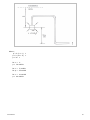
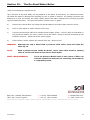
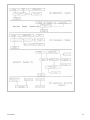
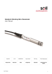
1
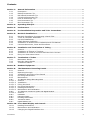
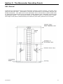
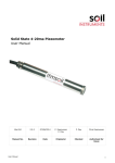
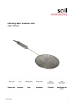
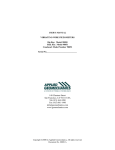
Hydraulic Piezometer
User Manual
Man046
2.0.2
04/07/2014
Chris Spalton
Andy Small
Chris Rasmussen
Manual No.
Revision
Date
Originator
Checked
Authorised for
Issue
User Manual
1
Contents
Section 1 :
1.01
1.02
1.03
1.04
1.05
1.06
1.07
General Information ................................................................................................................. 4
Description ...................................................................................................................................... 4
Bishop Piezometer Tip .................................................................................................................. 4
Bull Nosed Piezometer Tip ........................................................................................................... 4
Cylindrical Piezometer Tip ........................................................................................................... 4
Push In Piezometer Tip................................................................................................................. 4
Disc Piezometer Tip ....................................................................................................................... 4
Mini Piezometer Tip ....................................................................................................................... 5
Section 2 :
Operating Principle ................................................................................................................... 6
Section 3 :
Performance................................................................................................................................. 7
Section 4 :
Pre Installation Preparation and Tube Connections ................................................... 8
Section 5 :
Borehole Installations.............................................................................................................. 9
5.01
5.02
5.03
5.04
5.05
5.06
Section 6 :
6.01
6.02
6.03
6.04
Section 7 :
7.01
7.02
7.03
Borehole Installation Incorporating a Sand Filter................................................................... 9
"Push In" Borehole Installation ................................................................................................ 10
Up Hole Installations ................................................................................................................... 10
Small Diameter Drillholes .......................................................................................................... 11
Installation in Shallow Soil Foundations and Fill Material .................................................. 11
Concrete Structures, Joints and Interfaces ............................................................................ 11
Installation and Termination of Tubing .......................................................................... 12
General .......................................................................................................................................... 12
Installation of Tubing in Trenches ........................................................................................... 12
Installation of Tubes in Conduits and Cast into Concrete ................................................... 12
Entry into Instrument House..................................................................................................... 13
Termination of Tubes ............................................................................................................. 14
Manometer Panels ....................................................................................................................... 14
Bourdon Gauge Panels ............................................................................................................... 14
Transducer Panels ....................................................................................................................... 14
Section 8 :
Readout Equipment ................................................................................................................. 15
Section 9 :
The Manometer Recording Panels ..................................................................................... 16
9.01
9.02
9.03
9.04
9.05
9.05.1
9.05.1.1
9.05.1.2
9.05.1.3
9.05.1.4
9.05.1.5
9.05.1.6
9.05.2
9.05.2.1
9.05.3
9.05.4
9.05.5
9.05.6
9.05.7
General .......................................................................................................................................... 16
Operating Principle ...................................................................................................................... 17
Installation and Filling of the Panels ....................................................................................... 18
De Airing Piezometers ................................................................................................................ 19
Maintenance.................................................................................................................................. 19
The Bourdon Gauge Recording Panel ............................................................................................ 19
General .......................................................................................................................................... 19
Installation .................................................................................................................................... 20
Filling the Panel ........................................................................................................................... 20
De Airing Piezometers ................................................................................................................ 20
Reading Piezometers .................................................................................................................. 21
Maintenance and Calibration ..................................................................................................... 21
The Electrical Transducer System with Digital Readout ................................................................. 21
General .......................................................................................................................................... 21
Installation ....................................................................................................................................... 21
Filling the Panels ............................................................................................................................. 22
De Airing Piezometers ..................................................................................................................... 22
Transducer Panel ............................................................................................................................ 22
Digital Readout Unit ........................................................................................................................ 22
Section 10 : Front Panel Display and Controls ...................................................................................... 24
10.01
10.02
10.03
User Manual
Reading Piezometers .................................................................................................................. 24
Maintenance and Calibration ..................................................................................................... 24
Charging the Digital Readout Unit ........................................................................................... 25
2
Section 11 : De Airing Equipment ............................................................................................................... 26
11.01
11.02
11.03
General .......................................................................................................................................... 26
Installation of Panel .................................................................................................................... 26
Preparation and Setting Up ....................................................................................................... 26
Section 12 : Operation and Recharging.................................................................................................... 28
Section 13 : Calculation of De Airing Pressures .................................................................................... 29
Section 14 : Calculating De Aired Water Volumes ............................................................................... 32
Section 15 : The De Aired Water Boiler .................................................................................................... 33
User Manual
3
Section 1 : General Information
1.01 Description
The hydraulic piezometer is made in a variety of shapes and sizes to suit different applications but
in all cases it consists of a hollow body, a porous filter element and connections for twin nylon
tubes.
1.02 Bishop Piezometer Tip
This piezometer is based on the design of Professor Bishop and is intended for use in partially
saturated soil. The ceramic filter element is very fine and restricts the entry of air or gas from the
soil. The air entry value is 2.1 kg/cm2 with a pore diameter of 1 micron and a permeability of 2 x
10-8 m/s. This is commonly called a high air entry filter, a confusing term because it really
means high resistance to air entry. The Bishop tip is conical in shape making it ideal for placing in
direct contact with the soil. A pair of brass compression tube fittings are located on the top end
cap together with an offset left hand threaded hole for the attachment of a placing adaptor. Both
end caps and support stem are made of brass. The ceramic element is retained between neoprene
washers.
1.03 Bull Nosed Piezometer Tip
This piezometer is similar to the Bishop and is intended for similar applications. The ceramic filter
is of the same air entry value, pore diameter and permeability. In this case the filter element is
cemented to a single brass end cap, on which are located a pair of compression fittings.
1.04 Cylindrical Piezometer Tip
This piezometer comprises a coarse ceramic filter element cemented between two plastic end caps.
A pair of brass compression fittings are located on the top end cap.The ceramic element has a pore
diameter of 60 micron and a permeability of 3 x 10 -4 m/s. This is commonly called a low air entry
filter, whereas it has a low resistance to air entry. This type will permit a greater flow through the
filter and is particularly suitable when testing the permeability of materials of greater permeability
than 2 x 10⁻⁸ m/s up to 3 x 10⁻⁴ m/s. This type is normally installed in a borehole, surrounded by
a sand cell.
1.05 Push In Piezometer Tip
This piezometer comprises a cylindrical ceramic filter retained with neoprene washers between
plastic end caps, one cylindrical, one conical, with a central brass support stem, protruding from
the top end cap to locate the special placing adaptor. A pair of brass compression fittings are
located on the top cylindrical end cap.
Two types of ceramic filter element will fit this tip, one being of the high air entry type for use in
partially saturated soil, the other a low air entry type.
As the name suggests this piezometer is designed to be pushed into soft soils, often at the base
of a borehole.
1.06 Disc Piezometer Tip
This comprises a circular high air entry ceramic element bonded into a circular PVC body. Two
brass compression fittings are located opposite each other on the periphery of the PVC disc. This
User Manual
4
tip is used at an interface, such as at the base of a footing, in concrete construction joints, at a
concrete lining/rock or retaining wall/soil interface.
1.07 Mini Piezometer Tip
This comprises a coarse low air entry plastic filter element supported and clamped between
brass end caps, with a pair of brass compression fittings located at the top.
This tip is intended for experimental models, and for use in small diameter percussive drill
holes.
The alternative hydraulic piezometer systems are shown diagrammatically in Figure 1.
User Manual
5
Section 2 : Operating Principle
The porous piezometer tip is installed and sealed at the measuring horizon and is connected to
the readout location by twin polythene coated nylon tubes. De aired water is circulated through
the tubes until both the tubes and the tip are completed filled. They remain filled throughout
the working life of the installation and can at any time be re flushed to remove air or gas that
may have accumulated.
The pore water pressure at the tip is transmitted through the filter element to the water in the
closed system. This pressure can be measured at the remote end of either tube, making a
correction for the head difference between the tip and the measuring gauge. As there is
negligible volume change in the system the response is fast.
The limitation of the system is that neither the readout gauge nor the highest level of tubing
should be more than 5m above the piezometric level, as cavitation will cause pockets of water
vapour to break the hydraulic continuity of the system.
User Manual
6
Section 3 : Performance
Readings may be taken as far as 500 m from the piezometer tip and if special precautions are
taken, up to distance as great as 1000m. In general there is no maximum depth for a
piezometer borehole.
The accuracy largely depends on the readout system employed.
READOUT SYSTEM
RANGE HEAD OF WATER
OVERALL ACCURACY
Mercury Manometer
5 to +60m
± 10mm head of water
Bourdon Gauge
5 to +500m
± 1% full scale
Transducer digital display
5 to +199.9m
± 0.25 full scale
User Manual
7
Section 4 : Pre Installation Preparation and Tube Connections
The ceramic filter should be soaked in clean water for at least 24 hours to remove air. The
ceramic should also be checked for damage and replaced if necessary. In the case of Bishop and
Push in tips the ceramic filter is easily removed. In both cases the nose cone unscrews from the
brass support stem. To avoid losing the retaining washers, thread them over the support stem
and screw on the nose. Having connected the nylon tubes, the ceramic is refitted with the
piezometer immersed in water to ensure an air free unit.
The piezometer tubing consists of single or twin nylon tube coated with 1mm thick polythene.
Great care should be taken not to damage the nylon when stripping the polythene coating.
By tightening the compression fitting, the olive is squeezed onto the nylon and held tightly
against a matching conical seat. Overtightening may cause the brass thread to strip or the olive
to pinch too deeply into the nylon. When tightening fittings on Push in, Cylindrical and Disc tips
it is important to hold the hexagonal stud of the compression fitting firmly with a spanner,
otherwise the stud fitting may be overtightened in the PVC or plastic end cap or body and
consequently damage the threads.
It is good practice to undo the tube nut and check that the brass olive is correctly positioned on
the nylon tubing.
The piezometer tubing where possible should be in a continuous length to the gauge house. If
this is impractical it is important that the tube ends are sealed to prevent entry of foreign
matter.
User Manual
8
Section 5 :
Borehole Installations
The borehole, diameter 75 150mm, is usually driven in soils using shell and auger and in rock
using rotary water flush drilling techniques. Air flush and consequent entrapment of air in the
ground should be avoided. The sides of the borehole in the vicinity of the piezometer tip should
be free from mud cake and debris. If the hole requires casing, this is withdrawn to keep pace
with the installing operation.
5.01 Borehole Installation Incorporating a Sand Filter
1.
On completion of the borehole, place coarse clean filter sand through the water and
compact to the proposed base of the piezometer tip. Allow sufficient time for the sand to
settle, particularly if there is a high water level in the borehole.
2.
If placing tubes and adaptor are to be used to locate the tip (Bishop, Cylindrical or Bull
Nosed) it is helpful to lay the tubes on the ground and measure them, marking with
coloured PVC tape the proposed depth, taking into account any borehole casing remaining
above ground level. If placing tubes are not used it is important to measure and mark the
depth on the connecting tubing.
3.
When attaching the left hand threaded placing adaptor to the offset threaded hole on top of
the piezometer, locate using no more than two full turns.
4.
The piezometer is lowered down the borehole to the required depth and further filter sand
is poured and tamped until the tip is covered by at least 150 mm.
5.
Take great care when removing placing tubes; rotate only clockwise, never rotate anti
clockwise.
6.
A plug to prevent entry of grout into the sand cell is usually placed in the form of bentonite
pellets or balls of stiff bentonite, normally not larger than 50mm diameter, dropped
through the water and tamped into place.
7.
Backfilling is completed to ground level with an impervious grout, generally a bentonite
cement mix placed through a tremie pipe positioned above the bentonite plug and
withdrawn as grouting proceeds.
User Manual
9
5.02 "Push In" Borehole Installation
The push in tip is designed for pushing into soft soils at the base of a borehole. The minimum
distance the tip is driven is its own length, so as to avoid contamination by grout. The tip may
be driven considerably further than its own length, but care must be taken to ensure that it is
not driven through more than one type of material otherwise a smear effect might lead to
misleading results.
1.
Lay the placing tubes on the ground and measure them, marking with coloured PVC tape
the proposed depth, taking into account any borehole casing remaining above ground level.
2.
Locate the tip on the placing adaptor and firmly holding the nylon tubes together with the
placing tubes; lower the piezometer down the borehole, keeping it as central as is practical.
On reaching the base of the borehole, bring weight to bear on the placing tubes and push
the piezometer to the required depth. If the required depth is not quite attained, at least
ensure that the tip has been pushed its own length and that its depth is known.
3.
Release the nylon tubes and carefully withdraw the placing tubes.
4.
The installation is sealed by placing a plug of bentonite pellets or balls of stiff bentonite,
normally not larger than 50mm diameter dropped through the water and tamped into
place.
5.
Backfilling is completed to ground level with an impervious grout, generally a bentonite
cement mix placed through a tremie pipe positioned above the bentonite plug and
withdrawn as grouting proceeds.
5.03 Up Hole Installations
As placing of sand filter material is difficult, sponge rubber may be used behind the tip to retain
it in position and act as a seal to prevent the backfill grout from fouling the porous element. It
will also be necessary to attach an air bleed tube to the piezometer tubing, from just below the
sponge rubber seal down to the neck of the drill hole.
Having pushed the tip with sponge rubber seal and air bleed tube into position, the piezometer
tubes, the air bleed tube and the grout pipe are sealed into the neck of the drillhole. Grout is
pumped through the grout pipe and by immersing the end of the air bleed tube in water, a
steam of bubbles should demonstrate the displacement of air. Continue grouting until grout
appears from air bleed tube. Seal the grout pipe and air bleed tubes and leave the grout to set
User Manual
10
5.04 Small Diameter Drillholes
Where drilling of large diameter holes is uneconomical, the Mini Piezometer tip may be installed
in a drillhole of not less than 25mm diameter. If the placing of sand filter material and
bentonite pellets is difficult, the sponge rubber as mentioned above may be used to retain the
tip in position and form a seal behind the tip.
5.05 Installation in Shallow Soil Foundations and Fill Material
In relatively stone free material a 300mm deep hole is formed by pushing the hole forming
mandrel into the soil. This leaves an impression into which the piezometer should exactly fit,
making close contact with the surrounding material. Above the piezometer the hole is backfilled
with the excavated material after removal of any large stones. This material should be carefully
compacted by tamping.
In rockfill of coarse granular material it is necessary to form a pocket of coarse clean sand
around the tip to prevent damage to the ceramic. It may even be necessary to have a graded
filter from coarse gravel to sand where there is a danger that the sand might be washed away
through the rockfill.
5.06 Concrete Structures, Joints and Interfaces
The Disc Piezometer is suitable for these applications. It can be cast into the base of a footing,
in concrete construction joints or at the interface between concrete retaining wall and soil.
Before casting the concrete it is important to check the tubing and connections by circulating de
aired water. Ensure that the tubing is carefully routed so as to avoid kinks or sharp bends.
When installing a Disc Piezometer at a concrete lining/rock interface, the tip is often mounted
on a pad of freshly mixed plaster of paris.
User Manual
11
Section 6 : Installation and Termination of Tubing
6.01 General
The twin hydraulic tubes from each piezometer are normally terminated in an instrument house
or chamber which may be located up to 500m away from the piezometer tip. Between the
piezometer tip and the instrument house the tubing must be protected from mechanical
damage, ultra violet radiation and freezing temperatures. Consequently the tubes are laid
underground in trenches, run through protective conduits or cast into concrete.
6.02 Installation of Tubing in Trenches
Where tubes are to be laid in a trench they should be protected for 150mm above and below by
compacted stone free material normally sand, silt or clay. Although sand is often most
convenient to use only silt of clay should be used where the creation of a drainage path would
be undesirable. Where the trench passes through the impervious clay core of an embankment
dam, additional cut offs across the trench may be necessary. If the trench is to be backfilled
using rockfill or coarse granular material, the thickness of the protective layer over the tubes
should be increased to 250mm.
The tubes should be laid loosely in the trench, snaked to prevent strain due to ground
movements; in most cases a wavelength of 3m and amplitude of 200mm should be sufficient.
In certain cases it may be advisable to separate the tubes from each other in the base of the
trench.
The tubes should be looped on crossing an interface where differential ground
movements might be anticipated. The tubing may also be looped at joints. When
making in line connections using brass compression fittings it is advisable to wrap them
afterwards with 'Denso' or similar waterproof tape. The number of line connections should be
minimised, using continuous lengths wherever practical. The tubes should be identified using
coloured PVC tape applied at regular intervals.
Where possible the correct functioning of the instrument should be checked before backfilling
the trench. When this is not practical it is strongly advised that tubing joints at least be left
exposed until the instrument can be tested. Compaction of backfill should be carried out using
only hand operated equipment. In certain cases hydraulic compaction may be effective and
convenient. It may be advisable to clearly mark out the position of the backfilled instrument
trench, particularly if there is to be further excavation or borehole drilling in the vicinity. In
any case a record of the trench position and depth should be kept.
6.03 Installation of Tubes in Conduits and Cast into Concrete
When running tubing through a protective conduit it is convenient to first bunch all the tubes
together and bind them with adhesive tape. Ensure that all tubes are clearly identified. It is
advisable to avoid line connections; as such joints become almost in accessible in the conduit.
When casting tubing into concrete it is advisable to avoid line connections. If these have to be
made, brass compression fittings should be wrapped with 'Denso' or similar waterproof tape. It
should be remembered that the concrete aggregate will contain particles that could cause
damage to the tubing if placed without due care. Concrete should never be poured from a
height directly onto exposed tubing, but be carefully hand placed over the tubing. Tubing runs
should be relatively straight, avoiding kinks and sharp bends.
User Manual
12
6.04 Entry into Instrument House
The tubes normally enter the instrument house or chamber through a special entry duct. This
comprises a 150mm i.d. heavy gauge rigid PVC flanged pipe separated from a bolt on flange
plate by a neoprene gland. The flange plate incorporates individual brass and neoprene glands
for up to 24 piezometer tubes (12 piezometers).
Tubes are fed through the loosened brass and neoprene glands individually. To ensure water
tightness, these glands are a tight fit over the tubing, so it is usually necessary to
lubricate the tubing with soapy water. Great care should be taken to identify each length of
tube as it is fed through the flange plate.
User Manual
13
Section 7 : Termination of Tubes
7.01 Manometer Panels
The piezometer tubes are routed along the bottom of the panels in the plastic slotted ducting.
The lid of this ducting may be removed by squeezing together the sides of the ducting. Each
tube is brought out of the ducting through the appropriate slot, threaded through the tube clips
and up to the triple valve unit. Polythene is stripped from the nylon tube which is then inserted
into the compression fitting of the triple valve unit. It is important to hold the valve body firmly
with a spanner when tightening the compression fittings; otherwise the valve may be over
tightened in the retaining block and damage the threads.
7.02 Bourdon Gauge Panels
As with the manometers the piezometer tubes are routed along the bottom of the panels in the
plastic slotted ducting and are brought out of the ducting through the appropriate slots, and
connected to the triple valve units.
7.03 Transducer Panels
The pairs of piezometer tubes are divided, one tube from each piezometer being routed through
the upper plastic slotted ducting, the other tube through the lower ducting. Remove the lid of
the ducting by squeezing together the sides. To avoid mixing up the pairs, connect the tubes
from one piezometer at a time, starting with the one to be connected furthest away from where
the tubes enter the ducting. Place the tube in the upper ducting and measure off sufficient
length to reach the isolating valve with at least 30mm to spare, cut and trim the tube using a
sharp knife or tube cutter. Strip the polythene from the end of the nylon tube and insert
through the appropriate slot in the ducting and into the compression fitting of the isolating
valve. Tighten the fitting with a spanner until moderate resistance is felt. Repeat this
procedure for the other tube in the lower ducting, ensuring that the tube is connected to the
isolating valve directly below the upper tube. Ensure that the manifold connections are clearly
identified.
User Manual
14
Section 8 : Readout Equipment
There are three reading systems for hydraulic piezometer installations:
1.
Mercury Manometer
2.
Bourdon Gauge
3.
Electrical Transducer with Digital Readout
Sections 3 has a table showing the respective performance of these three systems, but consider
the following points:
The most compact is the transducer system as there is in effect just one readout gauge
connected to all the piezometers through a manifold system. The transducer lends itself to
remote reading and automatic scanning.
The mercury manometer has the advantage of requiring no calibration checking.
The bourdon gauge has a greater range than either transducer or manometer, is more compact
than the manometer and is very simple and robust, requiring the minimum of maintenance.
The following sections cover these systems in detail, with instructions on installation and
reading procedures.
User Manual
15
Section 9 : The Manometer Recording Panels
9.01 General
A drawing of a manometer unit for one piezometer is shown in Figure 2 below. Two triple valve
units are used with each piezometer to connect the piezometer to the busbars and also the
double manometer. The upper end of each manometer unit is connected to a water header tank
or, where high pressures are to be monitored, a back pressure unit comprising a mercury pot
compensated system. The manometer scales are calibrated directly in metres head of water.
The height of the panel is determined by the maximum pore water pressure to be recorded.
User Manual
16
9.02 Operating Principle
a) With Header Tank
The pore water pressure at the tip is
u=H+A+B
Where;
H is the mercury manometer reading and A + B = an elevation constant for each piezometer tip.
b)
With Back Pressure Unit
The pore water pressure at the tip is
u = H1 + H2 + A + B
Where H1 and H2 are the manometer readings and A + B = an elevation constant for each
piezometer
User Manual
17
9.03 Installation and Filling of the Panels
The manometer panels should be mounted vertically and level on wooden battens fixed to the
instrument house wall. Brass screws and washers are provided for fixing the panel. (See section
7.01 for termination of piezometer tubing.)
Connect the busbars between panels using lengths of nylon tubing. The busbars on the first panel
are connected to the de airing unit, the busbars on the last panel are blanked off using the stop end
fittings supplied. The tee pieces on the open ends of the panels should be connected with 3.2mm
o.d. nylon tube and finally connected to the fitting on the header tank or back pressure unit. The
open ends are blanked off using stop end fittings. Using a tee piece and a suitable length of 4.8mm
o.d. nylon tubing make a connection between the upper busbar and the shut off valve on the
header tank.
Refer To Figure 1.
1.
The valves must be operated in the order given, commencing with all valves in the closed
position. Fill the busbars with de aired water from the de airing unit allowing the air to escape
by opening the stop end fittings at the end of each busbar.
2.
Fill each manometer in turn by applying de aired water under pressure to both busbars and
opening valves 1, 2, 4, and 5. Water will be forced up into the header tank. Close valves 1,2,4
and 5. If after filling all the manometers the header tank is not filled to the overflow datum
tube, with pressure in the upper busbar, open the shut off valve on the header tank until the
water begins to overflow.
3.
Disconnect the manometer tube at the bottom of the tee piece fitting marked A. Fit a stop
end cap on the tee piece and place the special funnel over the nylon tube at point A. The
funnel can be supported behind the tee piece fitting.
4.
With valve 1 open, gently operate valve 2 to force de aired water up the manometer tube and
into the funnel until it begins to overflow. Close valves 1 and 2.
5.
Draw a small quantity of mercury (approx. 60ml for a 20 metre head panel) into the syringe
and carefully inject it into the funnel. Open valve 3 and very gently open valve 2 until the
mercury starts to slowly drop down the manometer limb. When the mercury has come to rest
at an equilibrium position, close valves 2 and 3. It is a wise precaution to gently tap the
funnel while the mercury is running out, to ensure that no droplets remain in the funnel.
6.
To have maximum operating range it is desirable to have the manometer limbs half filled with
mercury. If there is too much mercury simply open valve 1 and very gently open valve 2
until the mercury is forced SLOWLY up to the funnel (the de aired water must be under
approx. 25 to 30 metres head of water to overcome the mercury head). Close valves 1 and 2.
Using the syringe, remove some of the mercury. Once again open valve 3 and very gently
open valve 2 until the mercury has come to rest at its equilibrium position and close valves 2
and 3. If necessary repeat this procedure until the optimum amount of mercury remains in
the manometer. Likewise if on the first attempt there is insufficient mercury, return the
mercury to the funnel using this procedure and add a little more to the funnel. As each
manometer should require the same quantity of mercury, filling subsequent manometers
should be relatively straight forward.
7.
Remove the funnel from the nylon tube, disconnect the stop end from the tee piece and
reconnect the tube. When all the manometers have been filled, top up the header tank. If a
constant head back pressure unit is incorporated in the system, the manometers are filled as
described above but using the water from cylinder B on the constant head back pressure unit
in place of the header tank.
User Manual
18
9.04 De Airing Piezometers
To de air each piezometer in turn calculate the de airing pressures and the volume of water
required to fill the two nylon tubes to the piezometer (Refer to Sections 5.5 and 5.6).
Open valves 1,3,4 and 6 (valves 2 and 5 closed) and circulate de aired water at the calculated
pressure through the piezometer tubing, measuring the amount on the graduated scale of the
pressure tank A of the de airing unit. Circulate water until no more air bubbles are seen to be
returning through the nylon busbars, checking that the volume of water returning corresponds to
the volume leaving the de airing unit.
Close valves 1 and 4 and open valves 2 and 5 to the water pressure. When equilibrium has been
reached in the piezometer tubes, the difference in mercury levels of each manometer should be
the same. If the differences do not agree closely, it is possible that some air is present in the
piezometer tubing and further de airing is required.
9.05 Maintenance
In cold weather it is advisable to heat the instrument house to prevent any damage to the mercury
manometers due to freezing.
9.05.1 The Bourdon Gauge Recording Panel
9.05.1.1 General
Drawing No. P2123 shows the Bourdon Gauge Panel for use with hydraulic twin tube piezometers.
Two triple valve units are used with each piezometer to connect the piezometer tubes to the
busbars and to the pressure gauge. Pressure gauges are available in various pressure ranges from
5 to +500 metres head of water.
The overall accuracy is ± 1% of full scale.
The pore water pressure at the piezometer is equal to the bourdon gauge reading plus a constant
equal to the head of water between the gauge and the piezometer tip. If the piezometer tip is
above the gauge this constant is negative.
User Manual
19
9.05.1.2 Installation
The gauge panel should be mounted vertically and level on battens fixed to the instrument house
wall. Brass screws and washers are provided for fixing the panels. The busbars along the top of the
gauge panels are connected to the tee piece connections at the bottom of the de airing panel using
suitable lengths of nylon tubing. Conventionally the upper busbar is connected to the supply side
(cylinder B).
The open ends furthest from the de airing unit are blanked off using stop end fittings. During initial
setting up these open ends are looped together using a small length of nylon tubing thus
completing a circuit. With this arrangement both busbars may be flushed with de aired water.
(See section 3.5.2 for termination of piezometer tubing.)
9.05.1.3 Filling the Panel
Refer to Drawing No. P2123
The valves must be operated in the order given, commencing with all valves in the closed position.
Fill the pipework, valves and gauges with de aired water from the de airing unit.
1.
With the ends of the two busbars joined together forming a loop, circulate de aired water by
applying a low pressure to the upper busbar and slight vacuum to the lower busbar.
2.
When the busbars have been thoroughly flushed, shut off the pressure and vacuum.
Disconnect the busbar ends and blank, off using the stop end fittings.
3.
Re apply the pressure and vacuum to the busbars.
4.
For the gauge nearest the de airing unit, open valves 1, 2, 4 and 5 as shown on the drawing,
thus allowing circulation of de aired water through the valves and busbars. Air will be
observed travelling along the lower busbar into the de airing unit return tank.
5.
When no more air is seen and only de aired water is returning, close valves 1,2,4 and 5.
6.
Disconnect the nylon tube attached to the bourdon gauge. Draw a small quantity of de aired
water into the syringe and carefully insert the flexible tubing into the bourdon gauge. Inject de
aired water into the bourdon gauge until it overflows. Gently remove the flexible tubing
ensuring that the de aired water continues to overflow. Open valve 1 and gently open valve 2
until water drips from the nylon connecting tube. Quickly refit the nylon tube to the bourdon
gauge and turn off valves 1 and 2.
7.
Repeat steps 4, 5 and 6 for each gauge in turn. If some air remains in the lower busbar after
flushing the gauge furthest away from the de airing unit, repeat steps 1 and 2.
9.05.1.4 De Airing Piezometers
To de air each piezometer in turn calculate the de airing pressures and the volume of water
required to fill the two nylon tubes to the piezometer (refer to Sections 5.5 and 5.6). Open valves
1,3,4, and 6 (2 and 5 closed) and circulate de aired water at the calculated pressure through the
piezometer tubing, measuring the amount on the graduated scale of the supply cylinder A of the de
airing unit. Circulate water until no more air bubbles are seen to be returning through the nylon
busbars, checking that the volume of water returning corresponds to the volume leaving the de
airing unit.
User Manual
20
9.05.1.5 Reading Piezometers
Close valves 1 and 4 and open and close valves 2 or 5 in turn to record the water pressure. When
equilibrium has been established in the piezometer tubes, the pressure gauge reading should be
the same with either valve 2 or 5 open. If the readings do not agree closely, it is probable that
some air is present in the piezometer tubing and further de airing is required.
9.05.1.6 Maintenance and Calibration
Periodically it is advisable to check the calibration and operation of the bourdon gauges. This can
be done by shutting off valves 3 and 6 to all the piezometers and inter connecting all the gauges to
the supply side of the de airing unit. By applying incremental pressures measured on the de airing
unit
the operation and calibration of each gauge can be checked. To re set the pointer to zero on any of
the gauges, a bourdon gauge pointer extractor is supplied.
In cold weather it is advisable to heat the instrument house to prevent any damage to the bourdon
gauges due to freezing.
9.05.2 The Electrical Transducer System with Digital Readout
9.05.2.1 General
Drawing No. P4142 shows a typical terminal layout for reading hydraulic piezometers using an
electrical pressure transducer. The piezometer tubes are connected to the isolating valves, one
tube to the upper the other to the lower manifold. Piezometers are read individually by opening the
appropriate isolating valve, thereby connecting the piezometer to the electrical pressure transducer.
The digital readout unit connected to the transducer displays the water pressure at the transducer.
The pore pressure at the piezometer is equal to the displayed reading plus a constant being equal
to the difference between the level of the transducer and the level of the piezometer. If the
piezometer tip is above the transducer this constant is negative.
There are various methods of checking the transducer calibration including a header tank, a back
pressure unit and a deadweight tester. The span is checked against a zero datum level 'U' tube,
the open end of this tube being at the level of the transducer diaphragm. It is from this level that
the piezometer constants are calculated.
The transducer system is the most compact taking up far less space in the instrument house than
either manometer or bourdon gauge systems. The transducer system has a greater range than the
manometer and a greater accuracy than the bourdon gauge. However, the principal advantage is
that the electrical transducer lends itself to remote reading systems and automatic scanning.
Furthermore, the readings are expressed in a digital form and are therefore unambiguous and less
likely to be misread.
9.05.3 Installation
The terminal manifold panel and transducer panel should be mounted vertically and level on
battens fixed to the instrument house wall. It is usual to mount the terminal panel centrally with
the de airing unit to the left and the transducer panel to the right hand side. If using a header
tank, mount this at the highest possible elevation in the instrument house.
Connect valves G and H to P and V of the de airing unit using suitable lengths of plain 4.8mm o.d.
nylon tubing. Connect the other end of the manifolds to valves A and B using suitable lengths of
3.2mm o.d. stainless steel tubing.
User Manual
21
The calibration device, whether header tank, dead weight tester or back pressure unit, is connected
to valve C using a suitable length of plain 3.2 o.d. nylon tubing.
9.05.4 Filling the Panels
The valves must be operated in the order given, commencing with all valves in the closed position.
NOTE:
To safeguard the transducer, the transducer isolating valve should be in the closed
position except when taking readings.
Apply approximately 5 mH2O pressure to the de aired water in supply cylinder B of the de airing
unit, and open valves P and V.
Open valves G,A,B, and H to circulate water through the manifolds. With all the air removed, close
valves G,B and H.
To prime the calibration device, open valves C and G.
To prime the datum zero tube, open valves D and G.
To prime the transducer, carefully undo the tube nut on the transducer, holding the hexagon stud
with a spanner and withdraw the tube from the transducer.Open valve G and gently open the
transducer isolating valve until water just drips from the end of the tube. Hold the end of the tube
directly over the transducer orifice and drip water into it until full. Reconnect the tube to the
transducer and close all valves.
9.05.5 De Airing Piezometers
To de air each piezometer in turn calculate the de airing pressures and the volume of water
required to fill the two nylon tubes to the piezometer.
Open valves E,F,G and H (valves A,B,C,D, and I are closed) and circulate de aired water at the
calculated pressure through the piezometer tubing, measuring the amount on the graduated scale
of
the pressure cylinder A of the de airing unit.
Circulate water until no more air bubbles are seen to be returning through the water in return
cylinder C of the de airing unit finally checking that the volume of water returning corresponds to
the volume leaving the de airing unit.
9.05.6 Transducer Panel
The transducer panel is supplied with a 15V d.c. supply from the portable Digital Readout Unit
which is then regulated to 10V and supplied to the pressure transducer.
The outputs of the transducer are fed through two I.C. amplifiers so that 'zero' and 'span' controls
are provided to allow for fine adjustment to compensate any zero or amplifier offsets.
The inside of the pressure transducer box is coated with lacquer to damp proof the circuitry.
9.05.7 Digital Readout Unit
This unit is housed in a robust portable instrument case with hinged lid and carrying strap.
User Manual
22
It is powered by a 12V rechargeable battery which allows 20 hours continuous use between
charges. The unit must be connected to the transducer panel by a fly lead which is stored in the lid
of the readout unit. The unit comes complete with a 400mA constant current charger which is
mains operated and plugs into a socket on the readout front panel.
User Manual
23
Section 10 :
Front Panel Display and Controls
LABEL
COMPONENT
REMARKS
Metres mH2O
Liquid crystal displays 4½ digits
Displays either in mH2O
battery voltage depending
rotary switch setting
Zero
10 turn potentiometer
Zero adjustment
Transducer
Extendable cable with 4 pin plug
Plugs into transducer box
Off/Battery/set zero/Read
Rotary switch
Controls mode of operation of unit
2 Amp
Fuse holder
Holds 2A fuse
12 Volt
2-pin socket
Accepts
charger
10.01
Reading Piezometers
flylead
from
or
on
battery
Refer to Drawing No.P4142
Valves must be operated in the order given commencing with all valves in the closed position.
1.
Turn rotary switch to BATTERY. Battery voltage must be above 12.0V for the unit to operate
correctly.
2.
If the battery is sufficiently charged, connect the readout to the transducer box using the
flylead provided and turn the rotary switch to SET ZERO.
3.
Adjust the ZERO control to give +0.0 reading on the display. Lock the ZERO control into
position with the black lever on the side of the control.
4.
Turn the rotary switch to READ. Open valves D and I. Adjust the transducer box ZERO control
until the display reads +0.0. Close valve D.
5.
To read a piezometer, open valves E and F (for the appropriate piezometer). Firstly open
valve A and note the displayed reading, then close valve A and open valve B and note the
displayed reading. When completed gently open and close valve D to release excess pressure
in the system. Close all valves, unplug the flylead, replace the dust cap on the transducer box
socket, and turn off the readout.
10.02
Maintenance and Calibration
It is important to periodically check the SPAN of the pressure transducer. This involves supplying a
known pressure from the header tank, back pressure unit or dead weight tester.
1.
Repeat 1, 2 and 3 of Section 6.3.6.3.
2.
Open valves C and I to apply the known pressure to the transducer. Adjust the transducer box
SPAN control until the display reading corresponds exactly with the known pressure. Both of
the transducer box controls should now be locked by tightening the collets with a spanner.
3.
Close valve C. Gently open and close valve D to relieve excess pressure in the system. Close
valve In cold weather it is advisable to heat the instrument house to prevent any damage to
the panels due to freezing.
User Manual
24
10.03
Charging the Digital Readout Unit
To charge the battery, connect the charger to the mains, then to the readout unit. Rotary switch
on readout must be at the OFF position. Check that the light on the charger is on (this indicates
that the battery is being charged).
It is recommended that the battery is charged up overnight after every day's use to ensure that the
battery will be sufficiently charged for the next reading sequence.
User Manual
25
Section 11 :
De Airing Equipment
Refer to Drawing A4/800 259
11.01
General
The de airing unit consists essentially of pressure, supply and return tanks (A, B and C) and gauges
to measure water pressure and vacuum during circulation of de aired water. All these components
are mounted on a frame complete with valves and connecting pipework. Pressure and vacuum
pumps are used to operate the equipment. Pressure is applied to the de aired water in supply tank
B by forcing water from the pressure tank A into the bladder in B. Water from the supply tank may
then be circulated through the busbars and piezometer tubes back to the return tank C. The
volume changes measured in both the return and pressure tanks indicate the quantity of water
circulated through the system. The object is to completely replace the water in the piezometer
tubes with freshly de aired water.
The equipment has been fully tested to the operating pressure and vacuum before despatch.
However, it is possible that movements of the frame during transit may disturb the cylinders,
pipework or valves sufficiently to cause leaks when the equipment is operated. If any leaks are
observed during operation they should be eliminated by gently tightening the appropriate
component.
Never modify the arrangement without the full written approval of SOIL INSTRUMENTS LTD as
unauthorised modifications may by pass the safety system.
It is advisable to drain water from the equipment during cold weather to prevent damage to the
cylinders due to freezing.
11.02
Installation of Panel
The panel should be mounted vertically and level on wooden battens fixed to the instrument house
wall, at a convenient height for the operation of all the valves. The manifolds on the piezometer
terminal panels should be connected to the busbar tee piece connections on the de airing unit.
Blank off the other side of the tee pieces with the stop end fittings provided. Under normal
operating conditions the foot pressure pump is connected to the special connector on valve K and
the foot vacuum pump is attached to valve I.
11.03
Preparation and Setting Up
a)
The valves must be operated in the order given, commencing with all the valves in the closed
position.
b)
Attach the vacuum pump with the black hose supplied to valve E. Open valves E and G and
apply vacuum until the bladder is completely evacuated. Close all valves.
c)
Immerse one end of the red rubber tube into a container of clean water and attach the other
end to valve J at the base of the pressure cylinder A. Open valves J and E and operate the
vacuum pump drawing the water into cylinder A. When this tank is seven eights full, close
valves J and E. Remove the hose from valve E, open valve E to release the vacuum, and then
close.
d)
Prepare de aired water in the de airing boiler, allowing it to cool. Connect valve S on the
boiler to valve M on cylinder C using the red rubber hose. Attach the vacuum pump to valve I,
open valves I and M and release the vacuum from the boiler by opening valve V on the boiler.
User Manual
26
Open valve S and by operating the vacuum pump draw the de aired water into cylinder C until
it is three quarters full. Close valve M and I.
e)
Remove the vacuum hose and open valve I to release the vacuum. Open valves G and L,
attach the vacuum hose to valve G and draw the de aired water from cylinder C into cylinder B
by operating the vacuum pump until cylinder C is only one eighth full. Close all valves. To fill
cylinder B completely it is necessary to repeat the operation but this time only half filling
cylinder C with de aired water. When cylinder B is almost full close all valves. Remove the
vacuum hose from valve G.
f)
Open valve K and operate the pressure pump to bring the pressure in cylinder A to
approximately 5 10 mH2O. Gently open and close valve G thereby inflating the bladder,
displacing the de aired water in cylinder B and forcing out any remaining air. (If the air were
to be removed by applying a vacuum at valve G there is a risk of damaging the pump by
drawing water into it.) Any bubbles of air that cling to the rubber bladder and walls of the
cylinder B should be dislodged by slapping the sides of the cylinder until they rise and
accumulate under valve G. They may then be removed with pressure in cylinder A and
momentarily opening valve G. It is important that cylinder B is completely filled with de aired
water and all air excluded. Release pressure from cylinder A by opening valve E, and close all
valves.
g)
Attach the vacuum hose to valve E, open valves E, L and I and by supplying vacuum to
cylinder A, water is drawn from inside the bladder to cylinder A, thus drawing de aired water
from cylinder C into cylinder B. When the bladder is fully deflated the cylinder A will again be
seven eighths full of water. Close valves E, L and I. Remove the vacuum hose and open and
close valve E to release vacuum in cylinder A.
h)
Open valves I and M to drain the water from tank C. Close all valves. Attach vacuum hose to
valve I. The panel is now fully hanged with de aired water and ready for operation.
User Manual
27
Section 12 :
Operation and Recharging
The valves must be operated in the order given, commencing with all valves in the closed position.
a)
Attach the vacuum hose to valve I. Open valve K. Operate the pressure pump until the
desired pressure is reached in cylinder A, as indicated by the pressure gauge. Having
calculated the optimum de airing pressures (see Section 5.5), if a vacuum is required on the
return cylinder C, open valve I and operate the vacuum pump until the desired vacuum is
reached as indicated by the vacuum gauge.
b)
Open valves P and V and appropriate valves for the selected piezometer to be de aired, and
circulate de aired water at the calculated pressure through the piezometer tubing, measuring
the amount on the graduated scale of the pressure cylinder A.
c)
Circulate water until no more air bubbles are seen to be returning through the water in
cylinder C finally checking that the volume of water returning corresponds to the volume
leaving the de airing unit.
d)
As de airing precedes the pressure and vacuum will drop slowly and it will be necessary from
time to time to re adjust these to the original calculated values. During operation of the unit
the bladder in cylinder B should not be allowed to distend to more than three quarters of the
volume of the cylinder. At this point it is necessary to recharge with e aired water as follows:
e)
Close valves P and V to isolate the busbars from the de airing unit.
f)
Open valves E and I to release the pressure and vacuum from the tanks, as indicated by zero
reading on the gauges. Close all valves. Disconnect the vacuum hose from valve.
g)
Drain cylinder C by opening valves I and M.
h)
Attach the vacuum hose to valve I and the de aired water supply to valve M. Operate the
vacuum pump and draw de aired water into cylinder C until three quarters full. Close valves M
and I.
i)
Continue as in sections 5.3.6 and 5.3.7 ensuring that the water in cylinder C does not empty
while being drawn into cylinder B (avoid drawing air into cylinder B).
User Manual
28
Section 13 :
Calculation of De Airing Pressures
Consider a piezometer tip in the soil during the de airing process as follows:
u = pore pressure in the fill at the tip.
p = pressure on the pressure side of the de airing unit.
v = pressure on the vacuum side of the de airing unit.
h = difference in head between the piezometer tip and the
pressure and vacuum gauges on the de airing unit.
fAB and
fBC = friction losses in the piezometer tube.
All pressures are measured with respect to atmospheric pressure.
For Equilibrium:
p = h + u + fAB
v=h+u
fBC
Since AB = BC and if no water flows in or out of the piezometer tip, the velocity will be the same
throughout the system then
fAB = fBC
p=
2(h + u)
v
In a piezometer installation h is known, v can be maintained at a known value, and u for each
piezometer tip can be estimated using previous pore pressure readings. In this way p can be
calculated for each piezometer and de airing carried out at the appropriate pressure. If the
piezometer lies below the readout point, the term h, the difference in head between the piezometer
tip and pressure and vacuum gauges on the de airing unit, changes sign and becomes negative.
When a piezometer tip has accumulated a lot of air, care should be taken to apply sufficient
pressure to drive water at least as far as the tip before applying a vacuum to the other tube, as
friction loss in the return tube carrying air is much less than in one carrying water, and air will be
drawn in through the piezometer tip from the surrounding fill.
Example 1.
User Manual
29
Where;
p = 2 (h + u)
v
p = 2 (10 + 5)
v
p = 30
v
for v =
0
p = 30 mH2O
for v =
5 mH2O
for p = 35 mH2O
for v = 10 mH2O
p = 40 mH2O
User Manual
30
Example 2
Where;
p = 2 (h + u) v
p = 2 ( 7 + 4) v
p= 6 v
for v =
p=
6 mH2O
for v =
p=
0
5 mH2O
1 mH2O
for v = 10 mH2O
p=
User Manual
4 mH2O
31
Section 14 :
Calculating De Aired Water Volumes
After calculating de airing pressures (see Section 5.5) it is important to determine the volume of de
airing water to be circulated through each piezometer.
The amount of de aired water required depends on the length of piezometer tubing between the
installed piezometer tip and the de airing unit.
Under normal conditions we use tubing with 2.8mm internal diameter and 4.8mm outer diameter
for lengths up to 200 metres and tubing with 3.8mm internal diameter and 6.4mm outer diameter
for lengths exceeding 200 metres.
Usually the tubing is installed as two separate tubes, each with a 1mm polythene sheath or as two
tubes within a single polythene sheath.
a)
Determine which size of tubing has been installed by precisely measuring the outer diameter.
b)
Calculate from installation layout drawings or physically measure the distance from the
installed piezometer tip to the de airing unit.
c)
Multiple installed length by 0.013 to give de airing water volume in litres for tubing with
4.8mm outer diameter.
or
d)
Multiple installed length by 0.023 to give de aired water volume in litres for tubing with 6.4
mm outer diameter. Add at least 10% to the calculated volume to allow for tube snaking etc.
User Manual
32
Section 15 :
The De Aired Water Boiler
Refer To Drawing No. A4/145 000 M
Up to 50 litres of de aired water can be prepared in the boiler at one filling. An immersion heater
coil heats the water to boiling thus expelling any air or gases in solution. By sealing the boiler and
allowing it to cool, the steam and water vapour above the water condense thus creating a partial
vacuum inside the boiler. This prevents further solution of air or gases.
a)
Remove the central filler cap using the special spanner provided. Open valves V and S.
b)
Pour in clean water to within 100mm of the top.
c)
Connect the electrical cable to a suitable mains supply (either 110V or 230V as indicated on
the immersion heater coil cover). Switch on at the mains. Bring to the boil and allow to boil
forfifteen minutes. Switch off at the mains supply.
d)
Close valves V and S replace the central filler cap. Allow to cool.
WARNING:
Although the cap is fitted with a pressure relief valve, never boil with the
filler cap on.
NOTE:
With a partial vacuum inside the boiler, never open valve S before opening
valve V, as this will draw air into the de aired water.
SAFETY REQUIREMENTS:
The 4 psi Pressure Relief Valve in the centre of filler cap
must be checked at intervals not exceeding 12 months by
a competent person.
Bell Lane, Uckfield, East Sussex
t: +44 (0) 1825 765044
e: [email protected]
TN22 1QL United Kingdom
f: +44 (0) 1825 744398
w: www.itmsoil.com
Soil Instruments Ltd. Registered in England. Number: 07960087. Registered Office: 5th Floor, 24 Old Bond Street, London, W1S 4AW
User Manual
33
User Manual
34
BUSBAR
CONNECTIONS TO
DE-AIRING UNIT
TRIPLE
VALVE UNITS
STOP ENDS
4
1
5
PIEZOMETER
TUBES
2
6
3
GAUGE 1
PIEZOMETER
GAUGE 2
GAUGE 3
GAUGE 4
GAUGE 5
GAUGE 6
GAUGE 7
BOURDEN GAUGE
PLASTIC DUCTING
T.MILLWARD
BOURDON GAUGE PANEL FOR
HYDRAULIC PIEZOMETERS
5/3/2002
1
REDRAWN
DJP
NTS
P2123
dwgs\P\2123----1.dwg
User Manual
1
1
1
35
CONNECTIONS TO
DE-AIRING UNIT
CONNECT TO,
HEADER TANK,
PRESSURE UNIT OR
DEADWEIGHT
TESTER FOR
TRANSDUCER
CALIBRATION CHECK
G
E
A
C
D
I
B
H
PIEZOMTERER
TUBES
F
TERMINAL
MANIFOLD
PANEL
TRANSDUCER PANEL
DATUM
ZERO
TUBE
TRANSDUCER
ISOLATING VALVE
DIGITAL READOUT
T.MILLWARD
TRANSDUCER SYSTEM
FOR HYDRAULIC PIEZOMETERS
5/3/2002
1
REDRAWN
DJP
NTS
P4142
dwgs\P\4142----1.dwg
User Manual
1
1
1
36
T.MILLWARD
FRAME MOUNTED
DE-AIRING UNIT
5/3/2002
1
REDRAWN
DJP
NTS
800-259
dwgs\800\259----1.dwg
User Manual
1
1
1
37
VALVE 'V'
VALVE 'S'
FILLER CAP
IMMERSION HEATER
CABLE TO MAINS
SUPPLY
T.MILLWARD
DE-AIRED
WATER BOILER
6/3/2002
1
REDRAWN
DJP
NTS
145-000
dwgs\145\000----1.dwg
User Manual
1
1
1
38