1
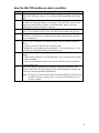
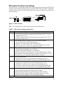
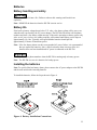
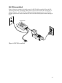
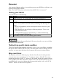
HomeSitter HS-700 Installation and Operations Manual Protected Home A Division of Control Products, Inc. 1724 Lake Drive West Chanhassen, MN 55317 Document No. 42420062A Table of contents Cautions and warnings .............................. 4 Description .................................................. 5 Physical description .................................. 5 General description .................................. 6 LEDs ......................................................... 6 Audible alarm ........................................... 7 What conditions activate the audible alarm? .................................................. 7 Operation..................................................... 7 HS-700 normal operation ......................... 7 How the HS-700 receives power .............. 7 Alarm operation ........................................ 7 How the HS-700 handles an alarm condition ............................................... 8 DIP switch functions and settings ............. 9 Initial setup.................................................. 10 Connections ............................................. 11 Connecting to AC power ...................... 10 Power up sequence.............................. 10 Battery Life, Installing Batteries ............ 10 Connecting the water sensor................ 11 Connecting to a phone line................... 12 Connecting the HS-700 and another device to the same phone jack ............. 13 Phone services and your HS-700 ............. 14 DSL and other digital phone services... 14 Calls using a calling card or pager phone number ..................................... 14 Creating pauses ................................... 14 Call to long distance phone numbers ... 14 Programming (entering phone numbers) 15 Before you start entering phone numbers 15 Entering phone numbers ...................... 15 Deleting phone numbers ...................... 16 Changing phone numbers .................... 16 Installation considerations ........................ 16 HS-700 assembled ................................... 17 Phone test ................................................ 18 Testing your HS-700 ............................ 18 Testing for a specific alarm condition ... 18 Ring count timer .................................... 18 Calling the HS-700 during an alarm event ................................................. 19 An in-phone line answering machine/voice mail with the HS-700 ............................. 19 How this works .................................. 19 Calling the HS-700 during an alarm event ................................................. 19 How to cancel an alarm call out sequence .............................................................. 20 Canceling an alarm call out sequence while listening to an alarm message . 20 Canceling an alarm call out sequence by calling the HS-700 ........................ 20 Canceling an alarm call out sequence with an answer machine/voice mail device in the phone line with the HS700 .................................................... 21 Remote status check ............................ 21 Troubleshooting .................................... 22 Technical information ........................... 23 Technical specification .......................... 23 FCC statement ................................... 23 Plug and jack use .............................. 23 Ring equivalence number (REN) ...... 23 Telephone network interferences ...... 24 Contact us ............................................. 24 Technical support.................................. 24 Warranty................................................... 25 Warrantor: Dealer, Distributor, Retailer, Manufacturer ......................................... 25 Warranty and remedy ....................... 25 Causes for termination of this warranty .......................................................... 25 Warrantors’ liability ............................ 25 Procedures for obtaining performance for warranty ....................................... 26 To return a product to Protected Home .......................................................... 26 How to request an RGA number ....... 26 2 Trademark All trademarks and registered trademarks are the property of their respective owners. The HS-700 HomeSitter is a trademark of Protected Home. Touch Tone® is a registered trademark of AT&T. Copyright © 2009 Protected Home: All rights reserved. No part of this work may be reproduced or used in any form or by any means—graphic, electronic, or mechanical—without written permission from Protected Home. Purchase date, date code and serial number For easy future reference during technical support and service, it is recommended that you write your purchase date, date code, and serial number of the device in the spaces below. The “date code” can be found on the label affixed to the bottom of the HS-700. PURCHASE DATE: DATE CODE: SERIAL NUMBER: Every effort has been made to ensure the information in this Installation and Operations manual is complete, accurate, and up-to-date. Protected Home and its vendors assume no responsibility for the result of errors in this manual, nor can it guarantee that changes in equipment and components made by other manufacturers, in reference to this manual, will not affect the operation or intended use of the HS-700. 3 Cautions and warnings Cautions indicate the possibility of poor equipment performance or potential damage to the equipment. Warnings indicate the possibility of injury to persons. The symbols shown below identify Cautions and Warnings: Cautions and warnings appear here and may appear throughout this manual where appropriate. Failure to read and understand the information identified by these symbols could result in poor equipment performance, equipment damage, or injury to persons. Caution Do not install the HS-700 in a confined space, such as a bookcase or in a cabinet, in direct sunlight, or where it might get exposed to water. Failure to observe this caution could result in poor performance or damage to the HS-700. Any changes or modifications to this equipment not expressed in this manual could cause poor performance or damage to the HS-700 and will void warranty. The use of any accessory not recommended for use with the HS-700 could lead to poor performance or damage to the HS-700. Use ONLY the AC power adapter sent with the HS-700. Use of other AC power adapters could result in damage to the HS-700. Do not install the HS-700 in high dust and debris areas. Failure to observe this caution could result in damage to the HS-700. Do not install the HS-700 in an area with chemical fumes or corrosive vapors. Failure to observe this caution could result in damage to the HS-700. Do not touch the barrel connector end of the AC power adapter with wet hands when plugged into AC power. Failure to observe this warning could result in an electrical shock. Do not throw batteries into a fire. Failure to observe this warning could result in an explosion. Do not install or connect the HS-700 to power or phone line during a lightning storm. Failure to observe this warning could result in an electrical shock. 4 Description Physical description Figure 1 identifies the parts of the HS-700. Figure 1: HS-700 Parts List Table 1: HS-700 Parts and Purpose Part 1. Key Pad 2. LEDs (3) 3. Battery Compartment 4. DIP Switches 5. Water Sensor Connector 6. Phone Jack 7. Power Jack 8. AC Power Adapter 9. Phone Cord 10. Water Sensor Purpose Used to enter the call-to phone numbers, activate a phone test, and cancel an alarm. Power, Program, and Alarm present operational status of the HS-700. LEDs do not function when operating on backup battery power. Accommodates two AA batteries for backup power during an AC power failure. These switches dictate how the HS-700 will respond to alarm conditions. Three-position terminal block used to connect the water sensor to the HS-700 for detecting water. RJ-11 phone jack is used to connect the HS-700 to a standard phone line. Connects to the barrel connector of the AC power adapter to provide 6 volts DC power to operate the HS-700. Converts AC power to 6 volts DC power to operate the HS700. Connects the HS-700 to the wall phone jack, length 7ft (2.1m). Normally open dry contact relay closes when water is detected, cable length 3ft (0.91m). 5 General description The HS-700 monitors your home for a variety of alarm conditions. When an alarm event occurs, the HS-700 calls the three entered phone numbers for the following alarms: Temperature drops below 45ºF (7ºC) or temperature rises above 85ºF (34ºC) DIP switch (selectable) AC power outages for more than 15 or 60 minutes (DIP switch selectable) HS-700 low battery condition (backup AA batteries) Water leaks (water sensor included) When a problem occurs at the monitored location, the HS-700 will start calling the call-list phone numbers sequentially, over a standard phone line and describe (in English) the current alarm(s). The HS-700 will continue calling until the alarm call out is canceled. LEDs The HS-700 has three LEDs: Power, Program, and Alarm located on its front panel. These LEDs present operating status of the HS-700. Table 2 explains the operational states of the three LEDs. Table 2: LED Operational States LEDs Power Operational States ON green when the HS-700 is plugged into the AC power adapter OFF when operating in battery mode to preserve power Program FLASHES red with a press of the PROGRAM key ON red (not flashing) while programming phone numbers (press of key 1, 2, or 3) OFF in normal operation mode OFF when AC power fails to preserve back-up battery power Alarm ON red when in alarm mode OFF when in normal operation mode OFF when AC power fails to preserve back-up battery power 6 Audible alarm The HS-700 produces a 40 db beep during an alarm event. You can turn the audible alarm (beep) OFF for alarm conditions ONLY by setting DIP switch “6” to the DOWN position. What conditions activate the audible alarm? The HS-700 will beep during the following alarm events: Temperature alarm (beeps once every 15 seconds) Low battery alarm (beeps once every 15 seconds) Power failure (beeps once every 10 seconds) Water detection alarm (beeps once every 15 seconds) Operation HS-700 normal operation In normal operations mode, the HS-700: Monitors the ambient temperature thru an on-board temperature sensor. Monitors for a power outage based on power through the AC power adapter (6 volts DC). Monitors the AA backup batteries for low power. Monitors the attached water sensor for the detection of water. How the HS-700 receives power The HS-700 receives power from a 6-volt AC power adapter, which comes with the HS-700. Two AA batteries (not included) supply back-up power to the HS-700 during an AC power failure. Alarm operation The HS-700 will monitor and send a factory-recorded voice message to the entered phone numbers for the following alarms: If the temperature falls below 45ºF (7ºC) or rises above 85ºF (34ºC) (DIP switch selectable) If power is out for either 15 or 60 minutes (DIP switch selectable) If the unit encounters a low battery condition If the HS-700 detects water from the water sensor 7 How the HS-700 handles an alarm condition Stage A. B. C. D. E. F. G. Description When an alarm occurs, the alarm LED lights up (if not an AC power failure), and the HS-700 emits a beep every so many seconds depending on the alarm type. The HS-700 starts calling the call-list phone numbers in sequence, attempting to deliver an in progress alarm voice message. If the HS-700 receives a busy signal or no answer after 10 rings, it will immediately hang up and start calling the next phone number in sequence. The HS-700 will continue calling the call-list phone numbers, in sequence, every 15 or 60 minutes (DIP switch selectable) until a called party answers. When the called party answers (person or answering machine), the HS-700 will deliver its factory pre-recorded alarm message, identifying the specific alarm condition(s). The HS-700 will continue its calling sequence until the following action is taken: Locally, press the CANCEL key on the key pad. Remotely, over the phone, press the number “1” key and then the “#” key on the key pad anytime during the alarm message. Once the alarm call-out sequence is canceled, the HS-700 will do one of two things: If the alarm is still active, the HS-700 allows you to call to hear the current alarm condition. If the alarm condition has been corrected, the HS-700 will not respond to the incoming call. When you cancel an alarm call out sequence, and correct the cause of the alarm, the HS-700 will stop beeping, the alarm LED will go out, and the unit will reset to normal operation automatically. Note: During an AC power failure alarm, the Alarm and Power LEDs do not turn ON to preserve battery power—but the unit will still beep every so many seconds. 8 DIP switch functions and settings The HS-700 has a 7-position DIP switch. The switch settings determine how the HS-700 will respond to specific alarm conditions. Figure 2 shows the DIP switch and Table 3 explains the functions of each switch. Turn the HS-700 upside down as shown in Figure 2 for proper DIP switch orientation. Figure 2: DIP Switches Note: Use a ballpoint pen or similar small object to set the DIP switches. Table 3: DIP switch settings and functions Switch 1 2 3 4 5 6 7 Function (switch in UP position is the default) Temperature low or high: UP, when the monitored environment temp falls below 45ºF (7.2ºC) an alarm message is sent. DOWN, when the monitored environment temp rises above 85ºF (29.4ºC) an alarm message is sent. Pick-up ring count when calling your HS-700 to cancel an alarm: UP, “5” rings before the HS-700 will answer. DOWN, “10” rings before the HS-700 will answer. If pick-up ring count is similar to an answering machine pick up, or how many rings you must wait before the machine responds. Monitors call out frequency: UP, call sequence happens every 15 minutes. DOWN, call sequence happens every 60 minutes. When the monitor goes into alarm mode, it begins calling the three call-list phone numbers. If the alarm condition is not canceled, the calling cycle will start again every 15 or 60 minutes until the alarm is canceled. Power out alarm timer: UP, if AC power is OFF for 60 minutes, an alarm message is sent. DOWN, if AC power is OFF for 15 minutes, an alarm message is sent. Auxiliary alarm message: UP, if the water sensor detects water, an alarm message is sent. DOWN, if an auxiliary event is sensed, an alarm message is sent. An auxiliary event may be some other device that is plugged into this unit that uses a dry contact. No other devices come included with this product. Audible alarm: UP, HS-700 will beep upon detecting an alarm condition. DOWN, HS-700 will NOT beep upon detecting an alarm condition. The alarm will beep during certain key pressing during set up or when entering test mode regardless of the switch position setting. Not used. 9 Initial setup Connecting to AC power Do not touch the barrel connector end of the AC power adapter with wet hands when plugged into AC power. Failure to observe this warning could result in an electrical shock. Do not install or connect the HS-700 to power or phone lines during a lightning storm. Failure to observe this warning could result in an electrical shock. Power up sequence Upon power up, the HS-700 LEDs will do the following: The Power, Program, and Alarm LEDs will light for a few seconds, then the Program and Alarm LEDs will turn OFF The Power LED will remain ON Note: A surge protector is recommended, but not provided. You can purchase a surge protector from Protected Home or from a local computer or hardware store. To connect AC power to the HS-700 through the AC power adapter, follow the number sequence shown in Figure 3. Figure 3: Connecting the AC Power Adapter 10 Batteries Battery handling and safety Do not throw batteries into a fire. Failure to observe this warning could result in an explosion. Note: REMOVE the batteries when the HS-700 is not in service. Battery life If the back-up battery voltage drops below 2.35 volts, a low battery alarm will be sent, even when the unit is powered by the AC power adapter. The HS-700 will call the call list phone numbers and issue a low battery alarm message. If the unit is operating on battery power only (after an AC power failure), the calling sequence will continue until battery power drops to approximately 1.9 volts. Typically, most good alkaline batteries should provide approximately 12 hours of continuous power. Note: If the low battery alarm was due to an extended AC power failure, it is recommended that you replace the batteries. Also, a false low battery alarm can occur if the AA batteries have not been installed and AC power is connected to the HS-700. You CANNOT enter phone numbers when the HS-700 is running only on battery power. Note: The HS-700 uses two AA batteries for backup power. Installing the batteries Note: To avoid a false low battery alarm, please connect the AC power adapter to the HS-700 and the wall outlet before inserting batteries. To install the batteries, follow the Steps shown in Figure 4. Figure 4: Battery Installation Connections 11 Connecting the water sensor To connect the water sensor to the HS-700, do the following: 1 Plug water sensor connector here me Ho te Sit r Water Sensor Note: You can lengthen the cable of the water sensor to 100ft (30.8m), using the equivalent size wire. (24 gauge, 2 conductor wire) Figure 3: Water Sensor Connected to HS-700 Connecting to the standard phone line To connect the HS-700 to a phone line, do the following: Figure 4: HS-700 Connected to Phone Line 12 Connecting the HS-700 and another device to the same phone jack If you need to connect the HS-700 and some other device, such as a telephone, to the same wall phone jack, simply use a phone jack splitter (not provided). To use a splitter, do the following: Step Action 1. Plug the line splitter into the wall jack as shown in Figure 7. 2. Plug one phone card into one jack on the line splitter, as shown in Figure 7. 3. Plug the second phone card into the other jack on the line splitter. 4. Plug the other end of the one phone cord into the HS-700. 5. Plug the other end of the remaining phone cord into the phone or other device. Figure 5: Phone Line Splitter Note: Both units will operate from the same jack independently without cross interference. Line Splitters can be purchased at most hardware and electronic stores. 13 Phone services and your HS-700 DSL and other digital phone services Please note that the HS-700 is designed and certified by the FCC to operate on a standard telephone line, provided by your local telephone company. DSL, Cable, or Digital phone service may work with the appropriate in-line filters. If you have questions or problems using one of those types of phone services, contact that specific phone service provider for assistance. Note: The HS-700 dials out using touch tone dialing only. During power failures, many alternative phone services such as DSL, Digital and Cable provided phone service DO NOT WORK. Those phone services require that power be on at the location for the phone to operate. The HS-700 will NOT be able to call out if the power is out when using these phone services. If you have a standard telephone line, power is supplied to this line by the telephone company and is usually not affected when power goes out at the monitored location. Calls using a calling card or pager phone number When using a calling card or pager system, you often need to include pauses to ensure that enough time is allotted to dial the phone number. To get a sense for how much time that may be needed, call the preferred calling card or pager to gain an understanding of how that system works. Often times, the calling card or pager system, may announce “enter your calling card number followed by the pound (#) key.” Make sure to include all necessary key presses as you enter the number. Also, while the card or pager system is talking (number of seconds), you will need to enter pauses for that time to allow the system adequate time to accept your telephone number. Creating pauses You can add pauses to your telephone number as you enter it into the HS-700 by pressing the STAR (*) key two times, which represents a 2-second pause. If you need to enter a 6-second pause, press the STAR (*) key six times. Note: Always press the STAR (*) key twice (in multiples of 2) to create an effective pause; otherwise, a single press of the STAR key will be literally translated as part of the dialed phone number. Calls to long distance phone numbers Long distance calling: make sure you enter the phone number exactly as you would when dialing a long distance call yourself (“1” and area code if needed). If dialing internationally, make sure you have the correct country codes and follow proper international dialing rules. Check with your phone company for assistance to determine the correct number. 14 Programming (entering phone numbers) You can program the HS-700 with up to three phone numbers (60 digits each), which it uses to communicate alarm messages. Before you start entering phone numbers DO NOT enter phone numbers of emergency services (fire, police or ambulance) into the HS-700. DO NOT forget the area code and then enter the phone number exactly as you would when making a personal phone call. Long distance dialing: enter “1,” the area code if required, and then the phone number. It is critical that you run a system test to validate the call-to numbers. For proper testing, it is recommended that a person at the call-to location confirms receiving the call. Note: You cannot enter phone numbers when the HS-700 is running only on battery power. Entering phone numbers Note: Phone numbers are stored in non-volatile memory (permanently stored in the HS-700 regardless of power failures or long-term storage). To enter phone numbers into the HS-700, do the following: Step 1. 2. 3. 4. 5. 6. 7. 8. 9. 10. Action Make sure the HS-700 is in normal operation mode. Press the PROGRAM key—a beep and the program LED starts flashing. Press the number “1” key to select the first location—a beep and the program LED is ON, not flashing. Enter the phone number (up to 60 digits)—beeps with each key press. Press the PROGRAM key—a beep and the program LED will start flashing. The number was entered successfully and the unit is still in program mode. Press the number “2” followed by a phone number to add the second phone number. Press the PROGRAM key—a beep and the program LED will start flashing. The number was entered successfully and the unit is still in program mode. Press the number “3” followed by a phone number to add the third phone number. Press the PROGRAM key-this will save the final programmed number Press the PROGRAM key again to exit program mode—a beep and the program LED goes out. (if programming less than 3 phone numbers, enter the Program Key to exit programming mode when complete. The program LED will go out) 15 Deleting phone numbers To delete a phone number, do the following: Step 1. 2. 3. 4. Action Press the PROGRAM key—a beep and the program LED starts flashing. Press the number 1, 2, or 3 key of the location of the phone number that you want to delete—a beep and the program LED is ON, not flashing. Press the PROGRAM key to delete the phone number—a beep and the programming LED starts flashing. The number was deleted successfully. Press the PROGRAM key to exit program mode when done—a beep and the program LED goes out. Changing phone numbers Follow the “entering phone number” procedure to overwrite any or all three phone numbers. Installation considerations The HS-700 should be installed in a dry, clean location near an AC power outlet and a telephone wall jack, as shown in Figure 8. Do not install or connect your HS-700 monitor to power or phone lines during a lightning storm. Failure to observe this warning could result in an electrical shock. Caution Do not install the HS-700 in a confined space, such as a bookcase or in-cabinet, in direct sunlight, or where it might get exposed to water. Failure to observe this caution could result in poor performance or damage to the HS-700. Use ONLY the AC power adapter sent with the HS-700. The use of other AC power adapters could result in damage to the HS-700. Do not install the HS-700 in high dust and debris areas. Failure to observe this caution could result in damage to the HS-700. Do not install the HS-700 in an area with chemical fumes or corrosive vapors. Failure to observe this caution could result in damage to the HS-700. 16 HS-700 assembled Figure 8 shows an example of an ideal setup of the HS-700 fully assembled. Place the HS700 on any flat surface, preferably a table top near an AC Power outlet and a phone jack as shown in Figure 8. Once the HS-700 is fully assembled and operational (power LED ON), perform a phone test to ensure that the HS-700 can call the call-list phone numbers during an alarm. Power ON LED Po P RO w er G TE 7 0 ST NC CA EL 4 8 1 5 2 6 g ra P ro 9 m 3 ar Al m Figure 6: HS-700 Assembled 17 Phone test After entering all phone numbers, it is crucial that you test your HS-700 to verify that it can reach the call list phone numbers. Note: The CANCEL key does not function when the HS-700 is in “test mode.” Testing your HS-700 To test the HS-700, do the following: Step Action 1. Make sure the HS-700 is powered up and in normal operation mode. 2. Press the TEST button—the HS-700 beeps and the alarm LED starts flashing. 3. Press the number 1, 2, or 3 key of the phone number that you want to contact—a beep and the alarm LED is ON, not flashing. The following will occur: HS-700 will immediately dial the desired phone number stored at key pad location 1, 2, or 3. Upon answering, the unit will play the following message: “This is a test of the HomeSitter Alarm.” It will repeat this message for approximately “1” minute and then hang up, and the alarm LED will go out. 4. Repeat Steps 2 and 3 to test the remaining phone numbers. The HS-700 does not provide any indication of call success; therefore, you must verify that the call was made successfully. Testing for a specific alarm condition To test for a specific alarm condition (temperature, water, power) you will have to simulate that specific alarm condition and then verify if the alarm phone calls went through. In those scenarios, you must cancel the alarm call out sequence and correct the alarm condition. Ring count timer The ring timer works in the following way: when the first call comes in during an alarm event, the timer starts counting down for “3” continuous minutes. If the HS-700 receives enough rings to answer (within “3” minutes), it will respond, and the ring counter will reset to “0” regardless if the three minutes have elapsed or not. Also, the timer will reset to “0” if no additional calls are received during a three minute period (multiple calls to the HS-700 within “3”minutes will not reset the ring timer). 18 Calling the HS-700 during an alarm event To call the HS-700 during an alarm, do the following: Step 1. 2. 3. Action Call the phone number of location where the HS-700 is located—the HS-700 will answer in 5 or 10 rings (DIP switch set) and deliver an alarm specific message. Listen to the message describing the alarm condition. Hang up the phone. An in-phone line answering machine/voice mail with the HS-700 When it is necessary to connect an answering machine or voice mail device to the same phone line as the HS-700, you can still use all the features of these devices, along with being able to check status and cancel an alarm call out of the HS-700. How this works During setup, you can manually set the HS-700 to answer on a specified number of incoming rings “5” or “10” (DIP switch 2, ring count). Set your answering machine or voice mail to answer in fewer rings than the HS-700. (For example, if the HS-700 is set to answer on 5 rings, set the other device to answer in “4” or fewer rings.) Therefore, when a call comes into the location of the HS-700, the answering machine/voice mail will respond first because it is set to answer in fewer rings than the HS-700. Calling the HS-700 during an alarm event The following example shows how to call the HS-700 during an alarm event: Criteria HS-700 ring count is set to “5” rings to answer (factory default DIP switch setting). Answering machine/voice mail is set to “4” rings to answer. You must make the appropriate number of phone calls to the location where the HS-700 is within “3” minutes or the timer in the HS-700 will reset to “0.” To get the HS-700 to respond given the above example criteria, do the following: Step 1. 2. 3. Action Call the phone number of the location where the HS-700 is located, and let the phone ring “3” times and then hang up. The internal 3-minute timer starts and the HS-700 tallies and remembers the number of rings. On your second call within “3” minutes, let the phone ring until the HS-700 answers. The HS-700 will answer first because it remembered the first “3” rings, and then it added the rings from the second call until the total reached “5,” then it answered before the answering machine/voice mail device (“4” rings to answer). Listen to the alarm message. Note: If the HS-700 is set to answer in 10 rings (the second choice on DIP SW2), you may need to place more calls within “3” minutes to get the HS-700 to eventually answer. 19 How to cancel an alarm call out sequence You can cancel an alarm call out sequence in two ways: Remotely, press the number “1” key and then the pound (#) key at any time during the alarm message. Locally, press the CANCEL key on the key pad. Canceling an alarm call out sequence while listening to an alarm message To cancel a call out sequence while listening to an alarm message, do the following: Step 1. 2. 3. 4. 5. Action Pick up the phone. Listen to the alarm message. When told, press the number “1” key. Press the pound (#) key within “1” minute to cancel the alarm call out. You can listen until you hear the HS-700 say goodbye or just hang up the phone. Note: Canceling the call out sequence does not cancel an active alarm (the HS-700 will continue to beep and the alarm LED will be lit). Canceling an alarm call out sequence by calling the HS-700 To cancel a call out sequence during an active alarm, do the following: Step 1. 2. 3. 4. 5. 6. Action Make the call to the HS-700 (phone number at alarm location) Wait for the HS-700 to answer (5 or 10 rings—DIP switch selectable) Listen to the alarm message. Press the number “1” key. Press the pound (#) key anytime during the message to cancel the alarm call out. Hang up the phone. 20 Canceling an alarm call out sequence with an answer machine/voice mail device on the same phone line To cancel the alarm call out-sequence, do the following: Step 1. 2. 3. 4. 5. 6. 7. 8. Action Make the call to the HS-700 (phone number at alarm location). Let the phone ring the desired number of times (before the other in-line device can answer). Hang the phone up. Call the number a second time within three minutes (The HS-700 keeps track of all the rings from the previous calls, accumulates them until the total ring count matches its ring count number 5 or 10, and then it will answer). Listen to the alarm message. Press the number ‘1’ key. Press the pound (#) key anytime during the message to cancel the alarm call out. Hang up the phone. Remote status check During normal operation, the HS-700 will not answer any incoming calls. You can call the HS-700 and get a response: If the HS-700 is in alarm mode. If the call out sequence has been cancelled for an alarm, but the alarm condition still exists, the HS-700 will answer and describe the alarm condition. 21 Troubleshooting Problem Power on LED is not lit CANNOT enter phone numbers HS-700 DOES NOT call out during a test HS-700 does not answer when I call I cannot cancel the alarm call out; the HS-700 continues calling out Receiving a false alarm Solution Power LED does not turn ON while running on batteries. Is the barrel connector end of the AC adapter plugged into the power jack on the HS-700, with the other end of the adapter is plugged into a ‘live” AC power source. Is the AC power wall outlet active? You cannot enter phone numbers if the HS-700 is being powered only by batteries. Is the HS-700’s AC power adapter plugged into AC power? Follow the “Entering Phone Number” procedure. Does the HS-700 have power? Is the phone service working properly (dial tone)? Re-check that the RJ-11 phone cord is fully plugged into the phone jack of the HS-700, and into the wall jack. Re-enter the phone numbers, verify area code and if the number “1” is required for long distance calling. If you are using a phone calling card, check to see that the calling sequence includes pauses as may be necessary to complete the call. The HS-700 will not answer if there is no active alarm event in progress. Is there an answering machine or voice mail in line with the HS-700? (see procedure for “In phone line answering machine/voice mail”) Verify that phone service is active at HS-700 location. Do you hear an alarm message that the alarm call out has been canceled? Are you pressing the correct cancel alarm keys during the alarm event: number “1” key and then the pound “#” key within one minute? The HS-700’s temperature sensor is accurate to within 3°F of the actual temperature. If your HS-700 is too close to a window during the winter months (below 45°C) or positioned in direct sun light (above 85°C) this could cause the HS-700 to false alarm. Check the HS-700 to see if the batteries installed, No batteries installed could cause the HS-700 to issue a false alarm. 22 Technical information Technical specification Specification Power requirements Temperature monitoring (DIP switch selectable) Humidity Dimensions Description Two power sources: 110VAC power adapter voltage stepped down to 6VDC, 200mA. 2 AA batteries for backup power (alkaline or lithium batteries, not provided) CHANGE BATTERIES after a prolonged AC power failure or yearly. Temperature drops below 45ºF (7ºC) or temperature rises above 85ºF (34ºC) 95% 5.8in L, 3.5in W, 1.5in H (147.3mm, 88.9mm, 38.1mm) approximately Ring Equivalence Number (REN) FCC statement This equipment complies with Part 68 of the FCC rules and the requirements adopted by the ACTA (American Council for Terminal Attachments). On the bottom of your HS-700 is a label that contains, among other information the FCC registration number for this product. If requested, this number must be provided to the telephone company. Plug and jack use A plug and jack used to connect this equipment to the premises wiring and telephone network must comply with the applicable FCC Part 68 rules and requirements adopted by the ACTA. A compliant telephone cord and modular plug is provided with this product. It is designed to be connected to a compatible modular jack that is also compliant. See installation instructions for details. Ring equivalence number (REN) The REN is used to determine the number of devices that may be connected to a telephone line. Excessive REN’s on a telephone line may result in the devices not ringing in response to an incoming call. In most, but not all areas, the sum of RENs should not exceed five (5.0). To be certain of the number of devices that may be connected to a line, as determined by the total RENs, contact your local telephone company. The REN for this product is shown above and is also identified as part of the FCC product identifier shown on the label on the back of your HS-700. 23 Telephone network interferences If this HS-700 causes harm to the telephone network, the telephone company will notify you in advance that temporary discontinuance of service may be required. But if advance notice isn’t practical, the telephone company will notify the customer as soon as possible. Also, you will be advised of your right to file a complaint with the FCC if you believe it is necessary. The telephone company may make changes in its facilities, equipment, operations or procedures that could affect the operation of the equipment. If this happens, the telephone company will provide advance notice in order for you to make necessary modifications to maintain uninterrupted service. If the equipment is causing harm to the telephone network, the telephone company may request that you disconnect the equipment until the problem is resolved. If your home has specially wired alarm equipment connected to the telephone line ensure the installation of your HS-700 does not disable your alarm equipment. If you have questions about what will disable alarm equipment, consult your telephone company or a qualified installer. Contact us To order the HS700, contact one of our Customer Service Representatives at: Protected Home 1724 Lake Drive West Chanhassen, MN 55317 952-448-2217 Fax: 952-448-1606 [email protected] Or visit us at: www.protectedhome.com Technical support If you need additional help installing or using your HS-700, contact our technical support department at 952-361-4101, Monday thru Friday, 8 AM to 5 PM CST. Or you can email your questions to: [email protected] 24 Warranty Warrantor: Dealer, Distributor, Retailer, Manufacturer Warranty and remedy We believe the HS-700 is a superior product. Although we take extreme pride in producing and testing a product that will function properly, we cannot guarantee that there will never be a defective unit or that a unit will function on all the thousands of phone lines and communication equipment in existence. For this reason, it must be clear that the warrantors are not insuring your premises or guaranteeing that there will not be damage to your person or property if you use this product. If you are not comfortable with our Limited Warranty, or completely satisfied with the product, we encourage you to return the unused product for a full refund within 30 days of purchase. Thank you for your understanding. One Year Limited Warranty: Protected Home warrants its product to be free from defects in material and workmanship under normal use for one year, and is not responsible for consequential damages or installation costs of any nature. In the event that the HS-700 does not conform to this warranty at any time during the period of one year from original purchase date, the warrantor will repair the defect and return it to you at no charge. The warranty is limited to replacement of the product ONLY. Secondly, because every phone line differs, we strongly encourage you to fully test this product in its actual application. This should include a full test, involving the product actually dialing to its designated locations and someone verifying the proper response. Causes for termination of this warranty This warranty shall terminate and be of no further effect at the time the products is Damaged by extraneous causes such as fire, water, power surge or spike, lightening, etc., or not maintained as reasonable and necessary Modified Improperly installed Repaired by someone other than the warrantor Used in a manner or purpose for which the product was not intended WARRANTORS’ OBLIGATION UNDER THIS WARRANTY IS LIMITED TO REPAIR OR REPLACEMENT OF THE PRODUCT ONLY. THIS WARRANTY DOES NOT COVER PAYMENT OR PROVIDE FOR THE REIMBURSEMENT OF PAYMENT FOR INCIDENTAL OR CONSEQUENTIAL DAMAGES. Warrantors’ liability It must be clear that the warrantors are not insuring your premises or guaranteeing that there will not be damage to your person or property if you use this product. The Warrantors shall not be liable under any circumstances for damage to your person or property or some other person or that person’s property by reason of the sale or use of this product, or its failure to operate in the manner in which it is designed. The warrantors’ liability, if any, shall be limited to the original cost of the product only. Use of this product is at your own risk. 25 Procedures for obtaining performance for warranty In the event that the product does not conform to this warranty, the product should be shipped or delivered freight prepaid to warrantor with evidence of original purchase. If in any way you’re not comfortable with this product or it’s Limited Warranty, we encourage you to return it unused within 30 days of original purchase date, with evidence of the purchase date. To return a product to Protected Home All products being returned to Protected Home must have a valid Returned Goods Authorization Number (RGA #) from Protected Home, regardless of why the product is being returned. Warranty returns will be honored only with a RGA #. Ship warranty return products prepaid to Protected Home, 1724 Lake Drive West, Chanhassen, MN 55317. Protected Home will, at its option, either repair or replace the product free of charge and return the repaired unit or replacement unit at the lower cost shipping prepaid. Products returned for credit are subject to a 25% restocking charge. Returns resulting from errors by the seller are not subject to this charge. All returns must include evidence of original purchase, showing purchase date. The RGA # should be clearly marked on the outside of the package containing the product. How to request an RGA number To request a RGA #, call Protected Home at 952-448-2217 and ask for Customer Service. Failure to have a RGA # may result in lost product or significant delays in handling your return. Also, products without a RGA # Clearly Marked On The Outside Of The Package are not the responsibility of Protected Home. 26 Index Alarm beep sequence .................................... 7 call in during .............................. 17, 18 cancel ........................................... 8, 19 cancel call out ............................ 19, 20 cancel key presses ............................ 19 conditions .......................................... 7 HS-700 handling of............................ 8 operation ............................................ 7 Battery install ............................................... 10 life .................................................... 10 safety................................................ 10 type .................................................. 10 Caution definition............................................ 4 Check Status ........................................ 20 Connect splitter to phone jack ........................ 13 to phone jack .................................... 12 water sensor ..................................... 12 Connector 3-position terminal block ................... 5 descriptions ........................................ 5 phone jack .......................................... 5 phone plug and jack use ................... 22 DIP Switch............................................. 5 audible alarm settings ........................ 9 call out frequency settings ................ 9 descriptions ........................................ 9 power out timer settings ..................... 9 ring-count settings ............................. 9 settings ............................................... 9 temperature settings .......................... 9 HS-700 parts and purpose ............................... 5 Installation ........................................... 16 LED alarm .................................................. 6 descriptions ........................................ 6 power ................................................. 6 program ............................................. 6 LEDs..................................................... 5 Phone #key ................................................. 14 calling cards and voice mail............. 14 changing numbers ............................ 15 delete number .................................. 15 dialing long distance ................................ 14 enter numbers .................................. 15 jack splitter ...................................... 13 pause key ......................................... 14 services ............................................ 14 star key ............................................ 14 test ................................................... 17 Power AC adapter ......................................... 5 backup ............................................... 7 battery .............................................. 10 connecting AC ................................. 11 input jack ........................................... 5 sources ............................................... 7 Product returns .............................................. 25 Ring count setting....................................... 9 equivalence number (REN) ............. 22 Ring Count timer ................................................ 17 Splitter phone jack ........................................ 13 Temperature monitoring ..................................... 6, 9 Warnings definition ........................................... 4 Warranty loss of .............................................. 24 product retures ................................. 25 Water Sensor cable lengthening ............................. 12 operation ............................................ 5 27 © 2009, Protected Home This manual may not be reproduced, modified, or distributed without permission from Protected Home Printed in the U.S.A. Document # 42420062A 28