1
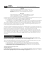
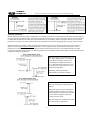
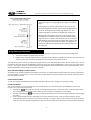
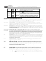
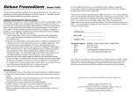
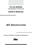
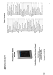
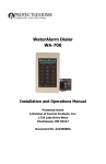
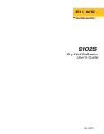
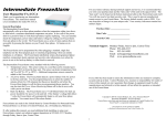
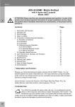
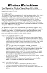
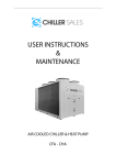
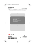
CONTROL
PRODUCTS
Innovative Technologies in Custom Electronic Design & Manufacturing
TC-9102 Series Surface Mount
Temperature Controllers
General Description & Applications
The TC-9102 Series Temperature Controller offers a versatile
solution for a wide variety of applications that may require 30
amp relays, short cycle delays and independent dual stages in
one convenient, easy to use controller.
The TC-9102 controller can accommodate input voltages from
12VAC to 240VAC. The TC-9102 comes with a temperature
sensor with a temperature range of -40 to 300F (-40 to
148°C). An optional RTD sensor is also available.
Features
• Single or Dual stage models with independent relay
control.
• Programmable set point, differential, short cycle delay
time, and temperature sensor calibration mode.
• Fahrenheit or Celsius Mode Selectable.
• LED relay status indicator.
• NEMA 1, high-impact plastic enclosure.
• Tamper resistant features to lock out and limit set point
adjustment and programming features.
• .56” high red LED display with three digit display in 1
degree increments.
• Displays current temperature.
• Durable touch-pad programming with LED display
prompts.
Specifications
Temperature Sensor Range:
• PTC sensor included: -40 to 300°F (-40 to 148°C) with
36” (.91M) 24AWG, 2 conductor wire. Nickel plated
copper sensor cap: 1.75”L (44mm) x .251” OD (6.38mm).
• Optional 1000 Ohm Platinum RTD sensor:
0 to 600°F (-17 to 316°C)
Relay Status Indicator: LED is on when relay is activated.
Dimensions: L 6.00” (15.24cm) x W 3.12” (7.92cm) x D 2.00”
(5.08cm)
Agency Approvals: UL and CUL recognized. RoHS compliant.
Power Requirements:
• Low Voltage (LV) models accept 12 to 24VAC & 24VDC.
• High Voltage (HV) models accept 120 to 240VAC.
Relay(s) Contact Rating:
1 relay on single stage models, 2 relays on dual stage models.
• SPST, normally open – switch up to 30A at 277 VAC
Ambient Operating Temp: 20 to 158°F (-6 to 70°C)
Ambient Operating Humidity: 90%RH at 95°F (35°C)
Accuracy: ± 2° F, ± 2°C
Wiring Connections
Power Connections
Stage 1
Stage 2
Normally Open
Normally Open
Sensor connections are on
the smaller circuit board
Sensor Connections
+5 VDC
Signal
No polarity.
Accepts up
to 240VAC
resistive/30
amps
Ground
120 VAC
COMMON
240 VAC
No polarity.
Accepts up
to 240VAC
resistive/30
amps
1
Low Voltage Power: On low voltage (LV) models, the
input voltage can be 12 to 24 VAC or 24 VDC. LV
models will only have a two position terminal block
marked “240” and “COM”. There is no polarity with
any of the low voltage inputs, so both power leads can
go into either of these terminal positions.
Sensor Type
Ground
PTC or RTD sensor Black
Signal
White
+5 VDC
NA
CONTROL
PRODUCTS
Innovative Technologies in Custom Electronic Design & Manufacturing
WARNING:
To avoid the risk of electrical shock, disconnect all power sources to the
controller and the equipment before wiring any connections. More than one
disconnect may be required to completely de-energize the control and the
equipment.
IMPORTANT:
All wiring must conform to local, national and regional regulations. Use copper
conductors only for all wire connections. Do not exceed the electrical ratings
for the TC-9102 series control or the equipment it is wired to.
Connect the proper power supply to the power connections on the terminal block as shown in the Dimensions & Wiring section
on page one. Note your model number indicates what input voltage is acceptable for this unit.
1. “HV” designates the unit can accept input voltage of between 110 and 240 VAC
2. “LV” designates the unit can accept input voltage of 12 or 24 VAC or 24 VDC. On low voltage versions, the TC-9102 will
have only a 240VAC and Common terminal block. There is no polarity on this terminal block for low voltage inputs.
The input power is independent of the power that can run through the relays. On all models, regardless of the input voltage,
the control relays can accept up to 240 VAC power at up to 30 AMPs. Connect the heating and cooling equipment to the
normally open (NO) relay terminal block connectors as appropriate.
The sensor may already be connected, but if not or if you ordered the RTD sensor option, you may need to connect this sensor
to the sensor connections. If you connected the optional RTD sensor, you will need to change the sensor selection menu in the
Hidden Access menus to get an accurate temperature sensor reading. See sensor connections on previous page.
Once the unit is powered up and the proper sensor is connected, the controller will display the current temperature. If the
current temperature does not appear to match the actual current temperature, you will have an opportunity to calibrate the
sensor. If the display is showing “Shrt” or “OPEn”, it means the sensor connection has a problem. “Shrt” indicates there is a
short in one of the wires of the sensor or in the sensor itself. “OPEn” indicates a cut wire or open connection on one of the
sensor’s wires.
How the Controller Works
When programming the TC-9102 temperature controller, it is important to determine how the TC-9102 controller should
operate for your specific application. You will need to know if you are using the controller in a heating application, a cooling
application or with a dual stage unit, it can even be used for both a heating and cooling application.
There are three different programming parameters that determine how the TC-9102 controller will operate for your specific
application. Dual stage units have separate programming parameters for each stage.
1. Temperature Set Point: The relays will always turn OFF or open when the temperature set point is reached.
2. Operating Mode (COOL, HEAT or OFF): This setting determines the application the controller is being used for.
3. Differential Setting: This is the number of degrees above or below the temperature set point the temperature is
allowed to rise or fall (depending up on the Operating Mode).
Temperature Set-Point Programming Functions:
Single Stage Applications:
On single stage models, the controller will either turn on or off the heating or cooling application based on the Temperature Set
Point set in the Set Point Programming function and the Differential set in Hidden Access Programming Function. The diagrams
below show how a single stage model operates for either a heating or cooling application.
2
CONTROL
PRODUCTS
Innovative Technologies in Custom Electronic Design & Manufacturing
Dual Stage Applications:
With dual stage models, each stage is independent, so one stage can be set as a cooling stage and the other a heating stage, or
both can be cooling or heating stages. When both stages are set to heating or cooling mode, each stage can have any set point
or differential value desired. If one stage is heat and the other is cool, however, there is a limitation on how you can set the
temperature set points to prevent the controller from having both heating and cooling applications running at the same time.
When both stages are in COOL or HEAT modes, the temperature set points can overlap or be separated by any number of
degrees. When using both HEAT and COOL applications in a dual stage controller, the controller will not let the user set
temperature set points that overlap. The TC-9102 controller automatically enforces a 2 second delay between one stage
turning off and another stage starting. The following diagrams show examples of how the Dual Stage TC-9102 controller can be
configured in different applications.
With both stages in the cooling mode, one
can “stage” cooling phases. The example
on the left shows stage 1 turning on to
cool to bring the temperature down to
17°. If the temperature continues to rise
for some reason, stage 2 kicks in at 25° to
boost the cooling down.
Alternately, each stage could be
separated by any number of degrees.
In this example, both stages are set to
HEAT, but the stages are separated by 2
degrees.
When both stages are set to either HEAT
or COOL modes, the stages can have the
same temperature set-point, be separated
by any number of degrees or they can
overlap as shown above.
With dual stages, the TC-9102 can be used
in a wide variety of applications.
3
CONTROL
PRODUCTS
Innovative Technologies in Custom Electronic Design & Manufacturing
It is possible to maintain a very tight temperature range by
setting one stage as a cooling stage and one stage as a heating
stage.
In the example on the left, stage 1 will heat up to 32°. At 32°,
the heating application will turn off and allow the application to
rise to 33° at which time the cooling stage will turn on. The
cooling stage will turn off when the temperature reaches 32°.
Although both temperature set points can be set at the same
temperature, the TC-9102 requires a minimum differential of 1
degree or more. In addition, the controller enforces a 2 second
delay between one stage turning off and the other stage turning
on. This is designed to reduce the possibility of tripping circuit
breakers should both the heating and cooling elements be on at
the same time.
Programming Instructions
Programming the TC-9102 series temperature controller is completed through two separate programming sequences:
1. Temperature Set-Point Programming Functions
2. Hidden Access Programming Functions for operation mode, differential, high & low set point limits, calibration, F/C
selection, short cycle delay time, temperature sensor selection and lock-out functions.
The programming menus are set up to display a program function first, followed by the numeric value or feature value. You can
change that value and then press the ENTER key to save the value, then press the MODE key to move to the next programming
function. The program functions are displayed with shortened text to represent the function that is to be programmed. For a
detailed explanation of all the program functions, see page 7.
WHAT HAPPENS DURING A POWER FAILURE?
All settings on the TC-9102 temperature controllers are saved in non-volatile memory which means they will stay programmed
even if the power is cut to the unit. This is crucial during a power failure since the unit will return to normal operating function
once the power is restored.
SAVING YOUR CHANGES:
To save your changes, you MUST press the ENTER value whenever you make a change to any program setting.
EXITING THE MENUS:
You can exit the menus in one of several ways. If you make changes, you will need to press the ENTER button after every
change or your values will not be saved!
1. Pressing the
button will cycle through each programming function and function value. At the end of the menu,
the unit will go blank for several seconds and then return the current temperature to the display.
2. Pressing and holding the
button for five seconds will allow you to exit the menu without having to cycle through
the menus.
3. When a programming function is displayed, you can press the down and up arrows to move through the various
programming options to select the one you wish to change. If you get to the last menu and press the down arrow one
more time, the unit’s display will go blank for several seconds and then return with the current temperature displayed.
4
CONTROL
PRODUCTS
Innovative Technologies in Custom Electronic Design & Manufacturing
PROGRAMMING TEMPERATURE SET POINT:
• It is assumed the unit is powered up and the current temperature is displayed.
• Shaded sections are only applicable to Dual Stage Units.
Step
1
2
3
4
5
6
Exit
PRESS
DISPLAYED
SP1
Flashing
Temp Value
SP1 value is
displayed.
SP2
Flashing
Temp Value
SP2’s value
is displayed
Blank Screen
FUNCTION or INSTRUCTIONS
SP1 represents Set Point #1 for the first stage. On single stage
models, there will only be one set point value, but on dual
stage models, there will also be a SP2 as shown below.
Using the
keys, adjust the temperature set point value for
stage 1.
Pressing ENTER saves the value and displays it without flashing.
For DUAL STAGE models ONLY, SP2 will appear, giving you the
ability to program the temperature set point for the second
stage.
DUAL STAGE MODELS ONLY: Using the
keys, adjust the
temperature set point value for stage 2.
DUAL STAGE MODELS ONLY: Pressing ENTER saves the value
and displays it without flashing.
For a few seconds, the screen will go blank and then the
current temperature will be displayed. This signifies the end of
this programming menu.
PROGRAMMING THE HIDDEN ACCESS MENU FUNCTIONS:
• It is assumed the unit is powered up and the current temperature is displayed.
• Shaded sections are only applicable to Dual Stage Units.
• For detailed explanation of the individual programming options, go to the end of this programming guide.
Step
PRESS
DISPLAYED FUNCTION or INSTRUCTIONS
Press and hold the DOWN ARROW key and then press the
1
OP1
MODE button. OP1 will be displayed representing the
+
Operating Mode for Stage 1.
Flashing
Using the
keys, select between the HEAT, COOL or OFF
2
OP1 value
operating mode for stage 1.
OP1’s value
Pressing ENTER saves the value and displays it without flashing.
3
is displayed
On DUAL STAGE UNITS only, the unit displays OP2,
4
OP2
representing the operating mode for Stage 2.
Flashing
Using the
keys, select between the HEAT, COOL or OFF
5
OP2 value
operating mode for stage 2.
OP2’s value
6
Pressing ENTER saves the value and displays it without flashing.
is displayed
7
dF1
dF1 will be displayed representing the differential for Stage 1.
Flashing
8
Using the
keys, adjust the differential setting for stage 1.
dIf1’s value
dIf1’s value
9
Pressing ENTER saves the value and displays it without flashing.
is displayed
ON DUAL STAGE UNITS only, dF2 will be displayed
10
dF2
representing the differential for Stage 2.
Flashing
11
Using the
keys, adjust the differential setting for stage 2.
dIf2’s value
5
CONTROL
PRODUCTS
Innovative Technologies in Custom Electronic Design & Manufacturing
12
dIf2’s value
is displayed
Pressing ENTER saves the value and displays it without flashing.
13
HSL1
HSL1 will be displayed representing the High Set Point Limit for
Stage 1.
14
15
16
17
18
19
20
21
22
23
24
Flashing
HSL1’s value
HSL1’s value
is displayed
LSL1
Flashing
LSL1’s value
LSL1’s value
is displayed
HSL2
Flashing
HSL2’s value
HSL’s value
is displayed
LSL2
Flashing
LSL2’s value
LSL2’s value
is displayed
25
CAL
26
Flashing CAL
value
27
28
29
30
31
32
33
34
35
36
CAL value is
displayed.
F or C
is displayed
Flashing
F or C
F or C
is displayed
SCYC
Flashing
SCYC value
SCYC value
is displayed
SEnS
Flashing
Ptc or rtd
Ptc or rtd
is displayed
Using the
keys, adjust the high set point limit for stage 1.
Pressing ENTER saves the value and displays it without flashing.
LSL1 is displayed representing the Low Set Point Limit
programming parameter.
Using the
keys, adjust the low set point limit for stage 1.
Pressing ENTER saves the value and displays it without flashing.
On DUAL STAGE UNITS only, the unit displays HSL2,
representing the High Set Point Limit for Stage 2.
Using the
keys, adjust the high set point limit for stage 2.
Pressing ENTER saves the value and displays it without flashing.
On DUAL STAGE UNITS only, the unit displays LSL2,
representing the Low Set Point Limit for Stage 2.
Using the
keys, adjust the low set point limit for stage 2.
Pressing ENTER saves the value and displays it without flashing.
CAL is displayed, representing the temperature sensor
calibration adjustment.
Using the
keys, adjust the calibration value of the
temperature sensor. This can be adjusted + 30° from the
reading on the display.
Pressing ENTER saves the value and displays it without flashing.
This is where you select if the unit should display in Fahrenheit
or Celsius degrees. Press MODE to change the selection.
Use the
keys to toggle between “F” and “C”.
Pressing ENTER saves the value and displays it without flashing.
SCYC represents the Short Cycle Delay Time. You select a value
in minutes anywhere from 0 to 15 minutes. Press MODE to
change the selection.
Using the
keys, set your desired Short Cycle Delay time.
Pressing ENTER saves the value and displays it without flashing.
SEnS allows you to select from one of two different sensor
options. Press MODE to change the selection.
Use the
keys to toggle between “rtd” and “Ptc”.
Pressing ENTER saves the value and displays it without flashing.
6
CONTROL
PRODUCTS
37
38
39
40
Innovative Technologies in Custom Electronic Design & Manufacturing
LOC
ALL or OFF
flashes
ALL or OFF is
displayed
Display goes
blank
This is the Lock-Out feature that prevents users from changing
the temperature alarm set point or the temperature alarm set
point. Press MODE to turn this ON or OFF.
Use the
keys to toggle between “ALL” or “OFF”
Pressing ENTER saves the value and displays it without flashing.
Pressing MODE at the end of this menu results in the display
going blank for several seconds followed by a display of the
current temperature reading from the temperature sensor.
EXPLANATION OF PROGRAMMING PARAMETER SETTINGS:
SP1 & SP2
TEMPERATURE SET POINT This is the temperature you wish to maintain for each stage. The TC-9102D model
has two independent relay stages. The TC-9102S is a single stage model. See page 2 for an explanation of
how the TC-9102 uses these set points in conjuction with the differential setting.
OP1 and OP2
OPERATING MODE Select the type of application this controller will be working with. Is it a heating
application or a cooling application. If you don’t wish to use this relay at all, select the OFF mode. Only Dual
stage units will haven a “OP2” mode. Factory default is COOL.
dF1 and dF2
DIFFERENTIAL This represents the number of degrees from the temperature set point the controller allows
the temperature to rise or fall before closing the relay control. See diagrams above. This is always a positive
number from 1 to 30. Zero is not allowed as a differntial value. Only Dual Stage units will have a “dF2” option.
The factory default setting is 3.
HSL1 and HSL2
LSL1 and LSL2
HIGH SET POINT LIMIT and LOW SET POINT LIMIT This is a tamper proof option that allows a user to
set maximum and minimum temperature set point limits to which a user can adjust the temperature set point.
If a user only wants people to be able to adjust temperature a few degrees, they can set very tight High and
Low Set Point Limits. Both High and Low set point limits can be set to the same temperature to prevent any
change in temperature set point. Only dual stage units have HSL2 and LSL2 options. Factory default value is
100° for the High Set Point Limits and 0° for the Low Set Point Limits.
CAL
CALIBRATION This option allows a user to field calibrate the temperature sensor. If the actual temperature is
2 degrees higher than what the TC-9102 is displaying, the user can enter a value of 2 in the calibration option
to make the TC-9102 controller display the correct temperature. You can enter a calibration value anywhere
from -30 to +30. Factory set at zero.
F or C
TEMPERATURE SCALE This option allows you to have the TC-9102 display in either Fahrenheit or Celsius
degrees. Factory default is Fahrenheit.
SCYC
SHORT CYCLE DELAY TIME The short cycle protection feature prevents the controller from short cycling a
compressor. A short cycle condition is when a relay controlling a compressor or other equipment cycles on
and off too quickly, possibly causing compressor or equipment damage. The minimum time between relay
state change is determined by the value entered in the Short Cycle Delay Time option. Enter a value anywhere
from 0 to 15 minutes. Factory default is 5 minutes.
SEnS
SENSOR SELECTION Choose if you have our PTC or RTD sensor connected. Factory default is PTC.
LOC
LOCK OUT FEATURE This feature allows the user to prevent anyone from adjusting the temperature set
point(s). If a person attempts to change any value, the display will show LOC for a short period of time to
show the user these adjustments are off-limits. Two options are available. Factory default is OFF.
1. ALL
Locks out all functionality of the Temperature Set Point menus. No changes can be made.
2. OFF
This turns off all lock-out features and allows a user full access to the Temperature Set Point
menu.
7
CONTROL
PRODUCTS
Innovative Technologies in Custom Electronic Design & Manufacturing
Normal Operation
During normal operation, the current temperature will be displayed. Relay indicator lights will be illuminated only if relays are
in the closed position.
Relay Operation:
1. Relays will always open when the temperature set point is reached.
2. Relays will always close when the temperature set point, plus or minus the differential value is reached.
3. On a dual stage unit, if using one relay for HEAT and the other for COOL, the TC-9102 will not allow the relays to be
both on at the same time. There will a minimum of 2 seconds between turning one stage off and turning another stage
on. This is designed to eliminate the possibility of a simultaneous switch between heating and cooling that could cause
a circuit breaker to trip.
FAILED TEMPERATURE SENSOR ALARM:
The TC-9102 can determine when the temperature sensor is defective or damaged and will alarm when such a condition occurs.
If the sensor has a cut wire or an open circuit, the display will flash “OPEn”. If there is a short in the sensor wire or the sensor
element, the display will flash “Shrt”. All controller functions will cease to operate until the problem with the sensor is fixed.
Technical Support & Contact Info
If you have further questions about the operation of your TC-9102 Temperature Controller and Alarm, please contact our
Customer Service department in one of the following methods:
MODELS AVAILABLE (Made in USA)
Phone: 952-448-2217
Fax:
952-361-9420
TC-9102S-LV
Single stage, power = 12 or 24 VAC, 24 VDC
TC-9102D-LV Dual stage, power = 12 or 24 VAC, 24 VDC
Email: [email protected]
TC-9102S-HV Single stage, power = 120 or 240 VAC
Web: www.controlproductsonline.com
TC-9102D-HV Dual stage, power = 120 or 240 VAC
Warranty
Control Products, Inc. warrants this product to be free from defects in material and workmanship under normal use for one year
and is not responsible for consequential damages or installation costs of any nature. Exposure to contaminants and extreme
environmental conditions such as moisture, temperature, chemicals, etc. may cause the unit to degrade or fail. Control
Products accepts no liability for product applications or customer application testing.
Custom Design & Modifications
Control Products specializes in complete design and manufacture of electronic controls. In addition to making any desired
modifications to this product, we can design a unique control specific to your application. Please consult our Customer Service
Department for further information on these services.
8
CONTROL
PRODUCTS
Innovative Technologies in Custom Electronic Design & Manufacturing
Menu Flow Charts
Powered up unit displays temp of any
attached sensors. If no sensors
attached, unit displays sensor error
message, per spec. Recommended
sensors be attached before
proceeding with programming
Program Temp
Set point for
stage 1
SP1 is displayed
MODE
SP1's value is
displayed &
flashes. UP/DWN
arrows to adjust
ENTER
SP1 value is
displayed
steady & saved.
Program Temp Set
point for stage 2
SP2 is displayed .
MODE
MODE
TO ACCESS
HIDDEN MENUS
Press Down Arrow
+ MODE
Operation Mode for
SP1. OP1 is
displayed
TEMP SET-POINT
MENU
Press MODE
MODE
HEAt/COOL/OFF mode
for SP1 flashes. Arrows
toggle selection
Unit display goes blank for
2 seconds and returns to
current temperature
ENTER
MODE
HEAt/COOL/OFF mode
for SP2 flashes..
Arrows toggle selection
SP2 value is
displayed
steady & saved.
TC-9102 PROGRAMMING MENUS
ENTER
Selected value
is steady and
saved.
Shaded boxes are only
used on dual stage units.
MODE
dif1 is displayed for
Differential setting
for SP1
MODE
Differential value for
SP1 flashes. Arrows to
change value.
MODE
ENTER
Selected value
is steady and
saved.
Temp Set point
menu Lock-out.
LOC is displayed .
MODE
Differential value for
SP2 flashes. Arrows to
change value.
ON or OFF flashes.
Use arrows to select
option.
MODE
MODE
dif2 is displayed for
Differential setting
for SP2
ENTER
ENTER
Temp. Sensor
selection. Ptc or rtd
is displayed.
Ptc or rtd flashes. Use
arrows to toggle to
selection.
MODE
ENTER
Selected value
is steady and
saved.
MODE
Short Cycle Delay
Time. SCYC is
displayed.
MODE
Low Set Point Limit
LSL1 is displayed
MODE
Low set point value for
SP1 flashes. Arrows to
change value.
ENTER
Selected value
is steady and
saved.
ENTER
MODE
High set point value for
SP1 flashes. Arrows to
change value.
Selected option
is steady and
saved.
MODE
Selected value
is steady and
saved.
MODE
High Set Point
Limit
HSL1 is displayed
SP2's value is
displayed &
flashes. UP/DWN
arrows to adjust
ENTER
MODE
Selected value
is steady and
saved.
MODE
Operation Mode for
SP2.
OP2 is displayed
MODE
MODE
Selected value
is steady and
saved.
Short cycle delay time
begins flashing. Arrows
to change.
MODE
Selected value
is steady and
saved.
ENTER
MODE
MODE
High Set Point
Limit. HSL2 is
displayed
MODE
High set point value for
SP2 flashes. Arrows to
change value.
ENTER
F or C flashes. Use
arrows to toggle for
selection
F/C selection.
F or C is displayed.
Selected value
is steady and
saved.
MODE
MODE
L:ow Set Point
Limit. LSL2 is
displayed
MODE
Low set point value for
SP2 flashes. Arrows to
change value.
Selected value
is steady and
saved.
ENTER
MODE
ENTER
Selected value
is steady and
saved.
Calibration.
CAL is displayed
MODE
9
Calibration value
flashes. Arrows to
change value.
MODE
Selected value
is steady and
saved.
ENTER
CONTROL
PRODUCTS
Innovative Technologies in Custom Electronic Design & Manufacturing
This page intentionally blank.
10
CONTROL
PRODUCTS
Innovative Technologies in Custom Electronic Design & Manufacturing
This page intentionally blank.
11
CONTROL
PRODUCTS
Innovative Technologies in Custom Electronic Design & Manufacturing
1724 Lake Drive West
Chanhassen, MN 55317 USA
MADE IN USA
Printed in the USA
DOCUMENT #: 42420054B
REVISION B (0210)
12