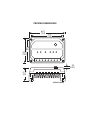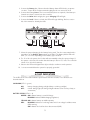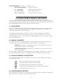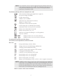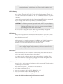
1
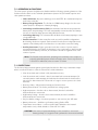
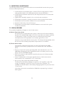
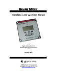
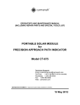
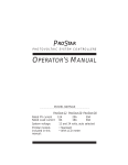
PROSTAR -12
SOLAR CONTROLLERS
OPERATOR’S MANUAL
PROSTAR VERSIONS INCLUDED IN THIS MANUAL
PS-15
PS-30
PS-15M-48V
Rated Solar Current
15A
30A
15A
Rated Load Current
15A
30A
15A
12/24V
12/24V
48V
Digital Meter Option
yes
yes
standard
Positive Ground Option
no
yes
yes
System Voltage
PROSTAR VERSIONS INCLUDED IN THIS MANUAL
1098 Washington Crossing Road
Washington Crossing, PA 18977 USA
phone: 215 321 4457
fax: 215 321 4458
email: [email protected]
PROSTAR DIMENSIONS
6.01
(153)
5.37
(136)
3.50
(89)
4.14
(105)
.18
(4.57)
2.17
(55)
inches (mm)
CONTENTS
1.0
GENERAL INFORMATION . . . . . . . . . . . . . . . . . . . . . . . . . . . . . . . 4
2.0
IMPORTANT SAFETY INFORMATION . . . . . . . . . . . . . . . . . . . . . 4
3.0
QUICK START INSTRUCTIONS . . . . . . . . . . . . . . . . . . . . . . . . . . . 4
4.0
LED INDICATORS . . . . . . . . . . . . . . . . . . . . . . . . . . . . . . . . . . . . . . 5
5.0
DIGITAL METER & MANUAL DISCONNECT . . . . . . . . . . . . . . . . 6
5.1 Digital Meter . . . . . . . . . . . . . . . . . . . . . . . . . . . . . . . . . . . . . . . 6
5.2 Manual Disconnect . . . . . . . . . . . . . . . . . . . . . . . . . . . . . . . . . . 6
5.3 Display Disconnects & Protections . . . . . . . . . . . . . . . . . . . . . 6
5.4 Self-Diagnostics (Self-Test) . . . . . . . . . . . . . . . . . . . . . . . . . . . . 6
6.0
INSTALLATION INSTRUCTIONS . . . . . . . . . . . . . . . . . . . . . . . . . . 8
6.1 General Installation Notes . . . . . . . . . . . . . . . . . . . . . . . . . . . . 8
6.2 Installation Steps. . . . . . . . . . . . . . . . . . . . . . . . . . . . . . . . . . . . 8
7.0
OPERATION. . . . . . . . . . . . . . . . . . . . . . . . . . . . . . . . . . . . . . . . . . . 10
7.1 Operator’s Tasks. . . . . . . . . . . . . . . . . . . . . . . . . . . . . . . . . 10
7.2 Operations & Functions . . . . . . . . . . . . . . . . . . . . . . . . . . . . . . 11
7.3 Protections. . . . . . . . . . . . . . . . . . . . . . . . . . . . . . . . . . . . . . . . . 11
7.4 Inspection & Maintenance . . . . . . . . . . . . . . . . . . . . . . . . . . . . 12
7.5 Special Features . . . . . . . . . . . . . . . . . . . . . . . . . . . . . . . . . . . . 12
8.0
BATTERY CHARGING INFORMATION . . . . . . . . . . . . . . . . . . . . . 13
8.1 ProStar Charging Method. . . . . . . . . . . . . . . . . . . . . . . . . . 13
8.2 Select Battery Type. . . . . . . . . . . . . . . . . . . . . . . . . . . . . . . . . . 13
8.3 ProStar Charging Features . . . . . . . . . . . . . . . . . . . . . . . . . . . . 13
9.0
TESTING AND TROUBLESHOOTING . . . . . . . . . . . . . . . . . . . . . . 14
9.1 Self-Diagnostics . . . . . . . . . . . . . . . . . . . . . . . . . . . . . . . . . 14
9.2 Technical Support . . . . . . . . . . . . . . . . . . . . . . . . . . . . . . . . . . . 14
9.3 Testing with a Power Supply . . . . . . . . . . . . . . . . . . . . . . . . . . 14
9.4 Troubleshooting . . . . . . . . . . . . . . . . . . . . . . . . . . . . . . . . . . . . 15
10.0 SPECIFICATIONS. . . . . . . . . . . . . . . . . . . . . . . . . . . . . . . . . . . . . . . 17
3
1.0 GENERAL INFORMATION
Thank you for selecting the ProStar solar controller. This second generation ProStar adds new
features and protections using highly advanced technology. Morningstar’s patented PWM battery
charging algorithm has also been further optimized for longer battery life and improved system
performance.
Many functions of the ProStar are unique. Although the ProStar is very simple to use, please take
the time to read this operator’s manual and become familiar with the controller. This will help you
to make full use of the many advantages the ProStar can provide for your solar system.
2.0 IMPORTANT SAFETY INFORMATION
”Always Put Safety First“
• Be very careful when working with batteries. Wear eye protection. Have fresh water
available to wash and clean any contact with battery acid.
• Charge only lead-acid batteries that are properly sized for the system.
• Explosive battery gasses can be present during charging. Be certain there is enough
ventilation to release the gasses.
• Use insulated tools and avoid metal objects near the batteries.
• Carefully read the battery manuals and other equipment manuals before installing
the solar system. Observe ALL precautions when working with batteries and power
electronics.
• Fuses or DC disconnects may be required in the system. These protective devices
are not part of the ProStar controller.
• Avoid large voltage drops in the battery wires. Use the Battery Sense connection for
best battery charging and system performance.
• Do not allow water to enter the controller.
• Avoid touching the controller heat sink. Under certain operating conditions, the heat
sink can become hot.
• Install the controller in a vertical position with adequate space for ventilation.
• Ensure that the system is properly grounded.
• SAVE these instructions for future reference.
3.0 QUICK START INSTRUCTIONS
This section provides a brief overview of how to get started using the ProStar controller. However,
please review the entire manual to ensure best performance and years of trouble-free service.
1. Mount the ProStar to a vertical surface. Allow space above and below the controller
for air flow. The heat sink MUST be in a vertical (up & down) position.
2. Make sure the Solar and Load currents will not exceed the ratings of the ProStar
version being installed.
4
3. Connect the Battery first. Observe that the Battery Status LEDs blink in sequence
one time. Torque all the ProStar terminals tightly, but do not exceed 35 in-ib.
4. Connect the battery Sense. This is recommended, but not required, if the battery is
located more than 5 meters from the controller.
5. Connect the Solar. With sunlight, the green Charging LED will light.
6. Connect the Load. If there is a fault, the LEDs will begin blinking. Refer to section
4.0 of this manual to identify the fault.
5
7
CHARGING
2
1
9
TEMP. SENSOR
BATTERY STATUS
BLINK: LOW
ON: LVD
3
1 – GEL
BATTERY 2 – SEALED
TYPE 3 – FLOODED
PV
+
LOAD
BATTERY
–
+
+
5
+
–
SENSE
4
UP
–
6
–
BATTERY
3
+
1
–
10
7. Select the proper charging for the battery being used. Turn the rotary switch with a
screwdriver to the Battery Type printed on the label. The Battery Status LEDs will
blink 1, 2 or 3 times depending on the Battery Type selected.
8. For 12 or 24 volt systems, the ProStar will automatically select the system voltage. If
the system is 24 volts, first confirm that the battery is above 15.5 volts. The controller
selects 12 or 24 volts at start-up.
9. Observe the LEDs and digital meter (if provided) to confirm normal operation.
10. It is recommended that the system be properly grounded.
4.0 LED INDICATORS
The 4 LEDs in the lower label indicate system status and various faults. These functions are
described below.
CHARGING (LED 1 – green)
ON:
battery charging during sunlight (always on during sunlight)
OFF:
normal during night (off during sunlight indicates solar reverse polarity or
overcurrent)
BATTERY STATUS (LEDs 2 – 4)
GREEN: ON indicates battery is near full charge
BLINKING indicates PWM charging (regulation)
YELLOW: ON indicates battery at middle capacity
RED:
BLINKING indicates a low charge state and a low voltage load disconnect
(LVD) warning
ON indicates the load has been disconnected (LVD)
5
FAULT INDICATIONS (G = green; Y = yellow; R = red)
G/Y/R blinking together
– battery select fault
R – Y sequencing
– high temperature disconnect
R – G sequencing
– high voltage disconnect
R/G – Y sequencing
– load short circuit or overload
5.0 DIGITAL METER & MANUAL DISCONNECT
A digital meter is available with the ProStar controller as an option. If your version includes the
meter display, this section will describe the information that can be displayed with the meter, and
the added capabilities that are enabled by the push button switch.
5.1 DIGITAL METER
A precision 3-digit digital meter will continuously display battery voltage, solar current, and the
load current. The meter automatically scrolls through these 3 displays. The 3 red LEDs will
indicate which parameter is being displayed.
The digital meter will operate from –30°C to +85°C. The values displayed are calibrated
electronically in production and are accurate to within a few percent. Please note, however,
that if the Battery Sense is not connected, the voltage displayed will be in error by the voltage
drops in the battery wires.
5.2 MANUAL DISCONNECT
The push button next to the digital display can disconnect the Load or both Load and Solar.
A second push of the button will return the controller back to normal operation.
LOAD OFF: A brief push of the button (less than 2 seconds) will disconnect the
Load. The Solar remains on and charging.
LOAD AND SOLAR OFF: If the button is held down for 2 seconds, the Solar will
also be disconnected.
When the button is pushed, the red LED inside the cap will light. In addition, the Load or both
Load and Solar will display “OFF“ in the digital meter to indicate the disconnected state.
5.3 DISPLAY DISCONNECTS & PROTECTIONS
The following protection functions and disconnect conditions will be displayed in the digital
meter when they occur:
LUD
HUD
HOT
OCP
0.0
LVD – low voltage load disconnect (load only)
high voltage disconnect (both solar and load)
high temperature disconnect (both solar and load)
overcurrent and short circuit protection (load, solar overcurrent)
short circuit protection (solar only)
5.4 SELF-DIAGNOSTICS (SELF-TEST)
If the push button is held down for 4 seconds, the ProStar will go into automatic self-diagnostics.
Note that the button must be released to start the self-test.
6
NOTE: The push button can be used to toggle through the displays faster.The
entire self-test takes 30 to 45 seconds. The load will be turned on for 0.1
second and may flash during the test. A short or overload condition
could cause a controller restart.
The following displays will occur (examples are used):
8.8.8 self-test started, checking the digital meter segments
12U
the system voltage (12/24/48)
15A
ProStar current rating
R1.5
software version installed
E04
a fault has been detected (see list below)
––display if no fault is found
25C
temperature measured at the controller
RP
remote temp probe is detected (if connected)
25C
temperature at the remote probe (if connected)
SEN
battery sense detected (if connected)
S-1
battery select position (1,2, or 3)
J-1
telecom noise jumper cut (change to on-off regulation)
END
end of the self-test
END – – – END
display continues if no error was detected.
END END
display continues if an error has been detected.
To terminate the self-test, push the button.
The self-test can be repeated to confirm the result.
Error List:
E0 I
E03
E04
E07
E08
E09
E I0
EII
E I2
E I3
Rotary switch battery selection failure
Voltage reference test failed (circuit, malfunctions)
Solar array current fault (circuit, FETs)
Load FETs off test (load connection, FETs shorted)
Load current fault (circuit, FETs)
Load FETs on test (load circuit, FETs open)
Internal temp sensor out of range high
Internal temp sensor out of range low
Remote temp probe out of range
Battery sense fault (battery V drop over 5V, no Sense negative connection)
NOTE: In addition to the self-test, observe the solar and load currents displayed
in the meter. The self-diagnostics plus the currents displayed in the meter
will provide a comprehensive test of the ProStar. Some faults may exist
that are not detected by the self-test, but the large majority of potential
faults will be tested and reported in this self-diagnostic test.
Refer to section 9.0 for more information.
7
6.0 INSTALLATION INSTRUCTIONS
The ProStar is installed in 10 steps. Follow the procedure in section 6.2 for a proper installation
and best performance.
6.1 GENERAL INSTALLATION NOTES
• The ProStar uses stainless steel fasteners, an anodized heat sink, and conformal
coating to protect from harsh conditions. However, for acceptable service life
extreme temperatures and marine environments should be avoided.
• The ProStar prevents reverse current leakage at night, so a blocking diode is not
required in the system.
• The ProStar is designed to regulate ONLY solar (photovoltaic) power. Do not connect
it to any other type of power generator. Do not attempt to regulate a wind turbine.
However, other power sources can be connected directly to the battery.
• The connector terminals will accept a maximum wire size of AWG #6 / 16 mm2
(solid/multistrand) or AWG #8 / 10 mm2 (fine strand). Use a flathead insulated
screwdriver, and torque tightly up to 35 in-lb.
• Fuses or DC disconnects may be required in the system. These protection devices
are not part of the ProStar controller.
NOTE: Carefully observe the LEDs at each connection. The LEDs will indicate
proper polarity and a good connection.
6.2 INSTALLATION STEPS
Refer to the wiring connection diagram in section 3.0.
STEP 1: Mounting
Inspect the controller for shipping damage. Mount the ProStar to a vertical surface
(4 stainless steel #8 self-tapping screws are included). Tighten the mounting screws
using care not to crack the plastic case. Do not install directly over an easily
combustible surface since the heat sink may get hot under certain operating
conditions.
NOTE: Heat sink must be in a vertical position (fins up and down).
Allow at least 15 cm (6 inches) space above and below the controller for air flow.
Install in an area protected from direct rain and direct sun.
If the controller is installed in an enclosure, some ventilation is recommended.
Do not locate in an enclosure where battery gasses can accumulate.
STEP 2: Ratings
Confirm that the solar array and loads will not exceed the current rating of the
ProStar version being installed.
Multiple ProStar units can be paralleled at the system battery to increase the solar
capacity, but do not parallel loads.
8
NOTE: The battery should be connected first. This will activate the controller
protection features, and will power the LEDs to guide installation and
start-up.
STEP 3: Battery
Before connecting the battery, measure the battery’s open-circuit voltage. It must be
over 8 volts to operate the controller. For 24 volt systems, the battery must be over
15.5 volts or the ProStar will regulate for 12V. The 12/24V auto selection is only done
at start-up.
Connect the battery and confirm that the 3 Battery Status LEDs blink in sequence. If
they do not light, check the battery polarity (+/–) and battery voltage.
CAUTION: The ProStar is protected against all faults EXCEPT a reversed battery
connection together with a polarized or short circuited load. CONFIRM that the battery + and – wires are correctly connected before
proceeding. Check the wires and the LEDs.
The green, yellow or red LED will light depending on the battery charge state.
Confirm one of these LEDs is on before going to the next step.
STEP 4: Sense
Battery sense connections are recommended if the controller is more than 5 meters
from the battery. The Sense, connected directly to the battery, will improve the
battery charging and control.
Both Sense wires (+/–) must be connected. A small wire size (18 AWG or larger) can
be used for the Sense because the current is very low. Note that the middle 2
terminals are for sense (with the smaller wire slots in the case).
NOTE: If the Battery input voltage is more than 5 volts different than the Sense
due to voltage drops or faulty connections, the Sense input will not be
recognized by the ProStar.
STEP 5: Solar
These terminals are used to connect the Solar (PV) array. First confirm that the solar
modules are wired for the same voltage as the battery.
Use caution, since the solar array will produce power whenever in sunlight. If the
solar is connected while in sunlight, the Charging LED indicator will light. Confirm
proper connection with the Charging LED.
STEP 6: Load
Turn the load off, and connect the load wires to the Load terminals. Turn the load on
to confirm a proper connection.
If the load does not turn on, it could be for various reasons:
• the ProStar is in LVD (red LED on)
• there is a short circuit in the load (LEDs blinking R/G – Y)
• there is an overload condition (LEDs blinking R/G – Y)
• the load is not connected, not working, or turned off
Confirm the load is working properly before going to Step 7.
9
STEP 7: Battery Type Selection
Using a small screwdriver, turn the rotary switch to select the Battery Type. There are
3 choices (see section 8.2):
1 = Gel battery
2 = Sealed battery
3 = Flooded battery
A proper selection will flash the 3 Status LEDs together: 1 time for Gel, 2 times for
Sealed, and 3 times for Flooded.
If the rotary switch does not make a good contact with one of the 3 selections, the
3 LEDs will start flashing together and continue until a good contact is made.
STEP 8: Confirm Installation
After the connections are completed, observe the LEDs to make sure the controller
is operating normally for system conditions. If the optional digital meter is provided,
observe that the display is scrolling with proper voltage and amperage values. A selftest can be performed with the digital meter (see section 5.4).
STEP 9: Grounding
For safety and effective lightning protection, the negative conductor of the solar
system should be properly grounded (see the NOTE below). In addition, the heat
sink can be grounded with a #8-32 UNC or M4 screw (0.136 hole provided).
The Solar, Battery, and Load negative terminals are all connected together inside the
ProStar per UL recommendations. No switching or measurement is done in the
negative current path.
NOTE: For positive ground versions, the Solar, Battery and Load POSITIVE
terminals are connected together inside the ProStar. The positive system
conductor must be properly grounded. Make sure the upper label of the
ProStar indicates “Positive Ground“ above the version number to confirm
this is a positive ground ProStar controller.
7.0 OPERATION
7.1 OPERATOR’S TASKS
The ProStar is a fully automatic solar system controller that includes many electronic functions to
protect both the controller and the solar system. Battery charging is also fully automated (see
section 8.0).
The only manual tasks performed by the operator are:
a. Installation (see section 6.2)
b. Battery type selection (see section 6.2, Step 7)
c. Disconnect button / Self-test (see section 5.2 and 5.4)
d. Reset if a load short circuit does not automatically clear (see section 7.3)
e. Maintenance (see section 7.4)
10
7.2 OPERATIONS & FUNCTIONS
The solar system operator should become familiar with the following operating functions of the
ProStar controller. Refer to the Technical Specifications (section 10.0) for actual setpoints and
other parameter values.
• 100% Solid State: All power switching is done with FETs. No mechanical relays are
used in the controller.
• Battery Charge Regulation: The ProStar is a PWM battery charger. See the next
section (8.0) for a description of battery charging.
• Low Voltage Load Disconnect (LVD): An automatic load disconnect protects the
battery from deep discharge. The load automatically reconnects when the battery
recovers. A 4-minute delay prevents false LVD disconnects.
• Low Voltage Warning: The red status LED will blink at low battery capacity to warn
of a possible LVD.
• Parallel Controllers: ProStar controllers work very well in parallel configurations.
No blocking diodes are required. Each controller must have an independent and
separate solar subarray and a load that does not exceed the controller’s rating.
• Auxiliary Generators: Engine generators and other sources of power may be
connected directly to the battery for charging. It is not necessary to disconnect the
ProStar from the battery. However, do not use the ProStar to regulate these other
sources of power.
Noise: The ProStar circuit minimizes switching noise and filters noise output. A
properly grounded system will also minimize noise. If noise is present in
a telecom or radio load, refer to section 7.5 below.
7.3 PROTECTIONS
The ProStar is fully protected against system faults listed below. Recovery is automatic except
where noted below. Refer to sections 4.0 and 5.0 for fault indications.
• Solar short circuit and overload – fully automatic recovery
• Load short circuit and overload – after 3 automatic load reconnect attempts (10
seconds between each attempt), the fault must be cleared and the load must be
turned off or disconnected for 10 seconds or longer to restore power to the load
terminals.
• Reverse polarity – fully protected except per Caution below
• Battery disconnected – the load is protected from voltage spikes
• High temperature – first the solar is disconnected, then the load will be
disconnected; auto reconnects
• High battery voltage – first the solar is disconnected, then the load will be
disconnected; auto reconnects
• Very low battery voltage – brownout protection, auto recovery into LVD state
• Battery select error – defaults to gel battery setting, flashes LEDs
• Temperature sensor failure – a remote probe failure defaults to the internal
temperature sensor, which defaults to a fixed 25°C if it fails
CAUTION: One source of potential damage to the controller is a reversed
battery polarity (+/–) together with a polarized or short-circuited load.
11
7.4 INSPECTION & MAINTENANCE
The following inspections and maintenance tasks are recommended at least two times per year
for best controller performance.
1. Confirm that the correct battery type is selected. Turn the rotary switch to another
setting and then back to the setting desired, and count the LED flashes.
2. Confirm that the maximum current of the solar array and load does not exceed the
ProStar ratings.
3. Tighten all the terminals. Inspect for loose or broken wire connections.
4. Check that the controller is securely mounted in a clean, protected environment.
5. Check that the air flow and the ventilation holes are not blocked.
6. Inspect for dirt, insects, nests, and corrosion.
7. Check that the controller functions and LED indicators are correct for the system
conditions at that time.
7.5 SPECIAL FEATURES
Two specialized capabilities will apply to some ProStar owners.
A) Remote Temperature Probe
An optional remote temperature probe can be soldered to the ProStar assembly at
any time. The standard cable length is 25 ft (7.6 m), and this can easily be extended
to 100 ft (30 m) or longer. The 2 probe wires are soldered to the main board
assembly between the temperature sensor and the green LED, at “J12“.
Instructions are provided with the remote probe. The ProStar will automatically select
the remote probe for battery temperature compensation if it is installed.
B) Telecom Noise Jumper
Some telecom equipment will produce noise when the ProStar begins PWM
regulation. If this occurs, a jumper can be cut to eliminate the noise. Instructions
follow:
• First, try to improve the system grounding which often eliminates the noise. The
PWM battery charging provides a significant benefit to the battery, and it is worth
trying to preserve the PWM charging.
• If the noise continues, disconnect the controller and remove the ProStar assembly
from its plastic case.
• Locate a vertical resistor in the upper right hand corner of the board, near the
microcontroller. This is identified as “J11“ on the board.
• Cut one leg of the resistor and separate the leads.
This will convert the battery charging to a typical “on-off“ regulation of the solar
energy. The switching is very slow, so the noise will not be noticeable. The
equalization and float features of the battery charging algorithm are preserved in the
“on-off“ mode.
In the future, this can be reversed back to PWM if the cut jumper leg is soldered
back together.
12
8.0 BATTERY CHARGING INFORMATION
The ProStar is an advanced, fully automatic solar battery charger. No adjustments are required
except to select the battery type at installation (see section 8.2 below).
VOLTAGE
4
EQUALIZE
NIGHT
1
FULL
CHARGE
2
PWM
REGULATION
3
FLOAT
NIGHT
TIME
8.1 PROSTAR CHARGING METHOD
The ProStar uses 4 stages of charging for rapid, efficient and safe battery charging. These are
shown in the diagram below:
1. Recharging with 100% of available solar energy.
2. PWM constant-voltage regulation to prevent heating and excessive battery gassing.
Pulse charging to restore full battery capacity.
3. Float: After battery is fully recharged, ProStar reduces to a float or trickle charge. The
transition depends on battery history. A load that exceeds available solar output will
return ProStar to the PWM mode.
4. Equalize: A boost charge that depends on elapsed time and battery history. Flooded
cells receive a vigorous equalization, sealed batteries a smaller boost to bring
uneven cells into balance and extend the battery life. Gel cells are not equalized.
8.2 SELECT BATTERY TYPE
The Battery Type rotary switch allows selection of 1 of 3 charging algorithms. These are broadly
defined as the following battery types as noted on the lower label:
1. Gel: Some gel and other battery types recommend lower regulation voltages and
no equalization. This setting regulates to 14.0V (for a 12V battery).
2. Sealed: AGM, “maintenance free“ and some types of gel batteries. Regulates to
14.15V (12V battery) with 14.35V boost charging.
3. Flooded: Vented cells that require water to be added. Regulates to 14.4V with
14.9V and 15.1V equalizations (12V battery).
The above values are 2 times for 24V, and 4 times for 48V.
The battery type selection can be changed at any time.
8.3 PROSTAR CHARGING FEATURES
Other ProStar capabilities for best battery life follow:
• Night Disconnect: The solar array automatically disconnects at night to prevent
reverse current leakage from the battery.
13
• Battery Sense: Good battery performance requires accurate charging. Voltage drops
in the battery power cables can distort the battery charging. The Sense wires
eliminate the voltage drops for optimized charging.
• Temperature Compensation: Four control setpoints (25°C reference) are
compensated for temperature (PWM regulation, float, equalization, high voltage
disconnect). The charging is compensated by –5 mV/°C /cell (–30mV/°C for a 12V
battery). Compensation is limited to minus 30°C.
• Remote Temperature Probe: An optional probe is available to measure temperature
at a location away from the controller. This requires soldering 2 wires to the ProStar
PCB. See section 7.5.
• Battery Equalization:
Calendar – 25 days
Equalization voltage
Cumulative time
Time starts above (V)
Battery History (flooded only)
Battery voltage falls below (V)
Equalize voltage
Cumulative time
Time starts above (V)
Reset 25-day calendar
The above battery setpoints are 2
Sealed
Flooded
14.35
1 hour
14.3
14.9
1 hour
14.6
N/A
11.7
15.1
2 hours
14.6
yes
times for 24V, and 4 times for 48V.
9.0 TESTING AND TROUBLESHOOTING
9.1 SELF-DIAGNOSTICS
If your ProStar includes the optional digital meter, refer to section 5.4 for how to perform a selftest of the ProStar. This will test for almost all failure modes of the ProStar and display any faults
that are found.
If the self-diagnostic test indicates that no failures were found, it is very likely that the problem is
with the solar system or battery.
9.2 TECHNICAL SUPPORT
Additional technical information and support can be found at Morningstar’s Website:
www.morningstarcorp.com
9.3 TESTING WITH A POWER SUPPLY
The ProStar can be tested with a power supply used in place of either the solar array input or the
battery. To avoid damage to the ProStar, observe the following cautions:
• Current limit the power supply to no more than half the ProStar rating.
• Set the power supply to 15 volts DC or less for 12V systems (30V for 24V systems
and 60V for 48V systems).
• Connect only one power supply to the controller.
Failure to follow these precautions may void the warranty.
14
9.4 TROUBLESHOOTING
The ProStar is assembled with automated equipment, tested with computers, and is protected
from faults. It is usually worthwhile to troubleshoot the entire solar system for faults, since the
ProStar will generally not be the cause of a problem. Most problems will be caused by wiring
connections, batteries unable to hold a charge, or faulty loads.
CAUTIONS:
1. Troubleshooting should be done by qualified personnel.
2. A battery can cause serious damage if shorted.
3. There are no user serviceable parts, fuses or circuit breakers inside the ProStar.
4. Observe all normal precautions when working with energized circuitry.
NOTE: If soldering is required, simply solder-through the conformal coating. The
coating is acrylic and does not affect soldering.
1. BATTERY IS NOT CHARGING
• Check the green CHARGING LED above the Solar input. With sunlight on the solar
array, this LED should be on.
• Check that the proper BATTERY TYPE has been selected.
• Check that all wire connections in the system are correct and tight. Check the
polarity (+/–) of the connections.
• Measure the solar array open-circuit voltage (disconnected from the controller) and
confirm it is normal. If the array voltage is low or zero, repair the fault in the array.
• Confirm that the load is not drawing more energy than the solar array can provide.
• If the BATTERY SENSE terminals are not used, there may be excessive voltage drops
between the ProStar and the battery. This is a common cause of undercharging
batteries. See section 6.2 to connect the Battery Sense.
• Check the condition of the battery. Determine if the battery voltage falls at night with
no load. If the battery is unable to maintain its voltage, it may be failing
• Measure the solar input voltage (during daytime) and battery voltage at the ProStar
terminals. If the voltages at the terminals are the same (within about 0.5 volts), the
solar array is charging the battery. If the solar voltage is close to open-circuit (about
20V), and the battery voltage is low, the controller is not charging the battery and
may be defective. Make sure the ProStar is not in regulation (PWM) for this test (see
section 4.0).
NOTE: If the battery is not being fully recharged, measure the voltage at the
battery terminals on the ProStar, and then at the terminals on the battery.
This should be done at midday with full charging from the solar array
(and not in PWM regulation). If the ProStar terminals are 1 volt higher
than the battery terminals, for example, this voltage drop will cause the
battery to regulate 1 volt below its desired regulation (PWM) voltage,
and it will take longer to recharge. In this case, the SENSE terminals
should be connected to the battery for accurate charging.
2. BATTERY VOLTAGE IS TOO HIGH
• First check the operating conditions to account for temperature compensation (a
15°C / 59°F temperature will increase PWM regulation by 0.3V for a 12V battery)
and automatic equalizations.
15
• Check that the proper battery type has been selected.
• Disconnect the solar array, and remove the battery wire from the ProStar battery
positive (+) terminal. Wait a few seconds and reconnect the battery positive terminal
(leaving the solar array disconnected). After start-up, the green CHARGING LED
should not be on. Measure the voltage at the SOLAR terminals (with the array still
disconnected). If battery voltage is measured at the SOLAR terminals and the green
LED is on, the controller may be defective.
CAUTION: If your ProStar is a positive ground version, references above to
Battery (+) terminals should be Battery (–) negative terminals.
3. LOAD IS NOT OPERATING PROPERLY
• Check that the load is connected and turned on. Confirm that no fuses or circuit
breakers in the system are tripped (there are no fuses or circuit breakers inside the
ProStar).
• Check all connections to the load, and battery connections. Make sure voltage drops
in the system are not too high (a voltage drop to the load will reduce the voltage at
the load).
• Check the LED indications on the ProStar. If the red status LED is on, the load has
been disconnected due to low battery voltage (LVD). This is a normal protection
function of the ProStar, and the load will be automatically reconnected when the
battery is charged by the solar array.
• If the LEDs are blinking, the load may have been disconnected for protection from
one of the following faults:
– short circuit or overload (R/G–Y sequencing)
NOTE: After 3 automatic retries, the fault must be cleared and the load must be
switched off or disconnected for 10 seconds or longer to restore power
to the load terminals
– high temperature (R–Y sequencing)
– high voltage (R–G sequencing)
• Measure the voltage at the BATTERY terminals. If above LVD and no faults are
present, the load should have power. Then measure the voltage at the LOAD
terminals, and if there is no voltage present the controller may be defective.
NOTE: For more technical and testing information, visit Morningstar’s Website:
www.morningstarcorp.com
16
10.0 TECHNICAL SPECIFICATIONS
Note: Values are for 12V versions. 24V versions are 2 times
(48V are 4 times) the 12V values unless noted otherwise.
ELECTRICAL
BATTERY SETPOINTS (@ 25°C)
• LVD
Gel
11.4
Sealed
11.4
Flooded
11.4
• LVD reconnect
12.6
12.6
12.6
• PWM regulation
14.0
14.15
14.4
• Float
13.7
13.7
13.7
• Equalization
N/A
14.35
14.9 / 15.1
• HVD (solar)
15.2
15.2
15.2
• HVD (load)
15.3
15.3
15.3
• Accuracy
12V
24V
48V
40 mV
60 mV
80 mV
• Min. voltage to operate
12/24V
8V
48 V
15 V
• Self-consumption
12/24V
48V
22 / 25 mA
28 mA
BATTERY CHARGING
• LVD current coefficient
–20 mV/amp load
24 V / 48 V
–40 mV / –80 mV
• High temp shutdown
70°C disconnect solar
80°C disconnect load
60°C reconnect load
50°C reconnect solar
PWM, constant voltage
• Temp comp. coefficient
–5mV/°C/cell (25°C ref)
• Temp comp. range
–30°C to +80°C
• Temp comp. setpoints
PWM, float, equalize, HVD
• Equalization
see section 8.3
MECHANICAL
• Voltage drops (max.)
solar / battery 0.2 V
battery / load 0.12 V
• Operating life
15 years
• Transient surge protect
pulse power rating
response
• Charge algorithm
1500 watts
< 5 nanosec
METER DISPLAY
• Dimensions: (inch)
6.01 x 4.14 x 2.17
153 x 105 x 55
• Weight
12 oz (0.34 kg)
• Wire terminals
solid
multistrand
fine strand
Euro-style
#6 AWG / 16 mm2
#6 AWG / 16 mm2
#8 AWG / 10 mm2
• Terminal diameter
0.210 in / 5.4 mm
• Torque terminals
up to 35 in-lb
• Type
LCD
• Temp rating
–30 to +85°C
• Voltage accuracy
0.5%
• Ambient temperature
–40 to +60°C
• Current accuracy
2.0%
• Storage temperature
–55 to +85°C
• Self-consumption
1 mA
• Humidity
100% (NC)
ENVIRONMENTAL
BATTERY STATUS LEDS
Falling V
G to Y
12.1
Y to Blink R
11.7
Blink R to R
11.4
Rising V
13.1
12.6
12.6
Specifications subject to change without notice.
Designed in the U.S.A.
Assembled in Singapore.
Y to G
Blink R to Y
R to Y
MS-ZMAN-PS01-A (April 01)
17