1
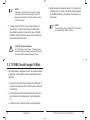
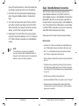
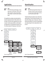
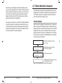
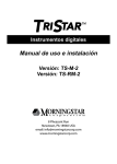
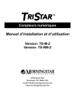
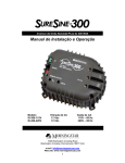
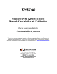
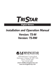
TRISTAR
Digital Meters
Installation and Operation Manual
Version: TS-M-2
Version: TS-RM-2
8 Pheasant Run
Newtown, PA 18940 USA
email: [email protected]
www.morningstarcorp.com
TS-RM-2 Dimensions in inches [mm]
Contents
1.0 Important Safety Information
2.0 Meter Description
2.1 Meter Versions
2.2 General Use
3.1 General Information
3.0 Installation
4
6
7
7
9
9
3.2 TS-M-2 Install (single TriStar)
10
3.3 TS-RM-2 Install (single TriStar) 12
3.4 Multi-TriStar Network Setup
14
4.0 Operation
4.1 Backlighting
4.2 Single TriStar System
4.3 TriStar MeterBus Networks
2
21
22
23
35
5.0 Troubleshooting
6.0 Warranty
7.0 Technical Specifications
40
43
44
TriStar Meter 2 Operator’s Manual
3
1.0 Important Safety Information
Installation Safety Precautions (Local Meter)
• Disconnect all power sources from the controller before mounting
the TS-M-2 local meter.
Save These Instructions
• Use the supplied RJ-11 meter cable to connect the meter to the
controller.
This manual contains important safety, installation and operating instructions for the TriStar Meter 2 digital displays.
The following symbols are used throughout this manual to
indicate potentially dangerous conditions or mark important
safety instructions:
• Bend the power conductors in the conduit wiring box so that they
do not touch the back of the meter.
• Apply silicon gel to the RJ-11 connections on the meter and the
controller for maximum protection from corrosion.
Installation Safety Precautions (Remote Meter)
WARNING:
Indicates a potentially dangerous condition. Use extreme
caution when performing this task.
!
CAUTION:
Indicates a critical procedure for safe and proper operation of the controller.
NOTE:
Indicates a procedure or function that is important for the
safe and proper operation of the controller.
Safety Information
• Read all of the instructions and cautions in the manual before
beginning installation.
• There are no user serviceable parts inside the TriStar Meter 2. Do
not disassemble or attempt to repair.
• There are no fuses or disconnects inside the TriStar Meter 2. Do
not attempt to repair.
4
Important Safety Information
• Disconnect all power sources from the controller before opening
the conduit box to connect the meter.
• Mount the TriStar Meter 2 indoors. Prevent exposure to the elements and do not allow water to enter the meter.
• Protect the RJ-11 wiring with grommets, conduit, and wire clips as
necessary.
• Apply silicon gel to the RJ-11 connections on the meter and the
controller for maximum protection from corrosion.
About this Manual
This manual provides detailed installation and usage instructions for the TriStar Meter 2 digital meters. Only qualified
electricians and technicians who are familiar with solar system
design and wiring practices should install the TriStar Meter 2.
The usage information in this manual is intended for the system owner/operator.
TriStar Meter 2 Operator’s Manual
5
2.0 Meter Description
TriStar controllers are technically advanced and professional
solar battery chargers and load controllers. Two digital LCD
meters are available for the TriStar family of controllers, and
their displays are identical. One version is mounted on the
controller; the other is mounted in a remote location.
This manual will help you to become familiar with the TriStar
meters’ features and capabilities. Some of these follow:
• Intertek ETL Recognized for use with Morningstar’s TriStar family
of charge controllers
• Complies with CE and LVD standards
• Suitable for 12, 24, 48 Vdc systems
• Fully protected from wiring faults
• Controller-mounted and remote versions can be used together
• Extended LCD temperature rating (-20oC to +70oC)
• Multilingual display (English, French, German, Portuguese, Spanish)
• Displays aggregate system data from multiple TriStar controllers
• Manual Ah resets and equalization control for individual controllers and for multi-controller systems
• Diagnostic capabilities
• View internal logged data stored in TriStar controllers that have
datalogging capability
• Remote version supplied with 30m (98.4 ft), cable may be shortened if needed
• Connections are by standard RJ-11 6-position modular plugs
• 5-year standard warranty
2.1 Meter Versions
This manual covers two standard versions of a digital LCD
meter that can be used with the TriStar family of solar controllers.
Version TS-M-2:
This local meter is provided as an assembly that replaces the
TriStar front access cover. The TS-M-2 meter mounts to the
TriStar controller.
Version TS-RM-2:
This remote meter is provided with a mounting plate and 30m
(98.4 ft) of cable. It is identical to the TS-M-2 version except
that the TS-RM-2 version can be mounted at some distance
from the controller.
Both meters can display the full range of operating and diagnostic information for the TriStar’s battery charging, load and
diversion operating modes.
2.2 General Use
The meter will display a great deal of information about the
TriStar controller and the operation of your system. In addition, the meters enable manual functions and controller diagnostics. These capabilities will increase your confidence that
the system is working properly and will help you to improve
system reliability, battery life, and system performance. It is
worth the time getting to know your meter!
The organization of the display screens is described in Section
6
Meter Description
TriStar Meter 2 Operator’s Manual
7
4.0. It is easy to move around the various display areas and
to scroll up or down, and left or right using the four pushbuttons as indicated below:
3.0 Installation
The TriStar meters can be added to the controller when it is
first installed, or at anytime after the controller has been in
service.
3.1 General Information
LEFT
RIGHT
UP
DOWN
Due to power requirements, there is a limit of two meters that
can be used with a single TriStar controller. There is also a
limit of five meters per MeterBus network. Any combination of
local and remote meter is permitted. Only one meter can have
an active backlight at any given time.
The installation steps will differ depending on the number of
TriStar controllers in the system.
For Single TriStar Systems:
• Mount the meter to the TriStar (TS-M-2) or in a remote location
(TS-RM-2)
• Connect the meter cable to the RJ-11 connectors
• adjust the meter settings
For Systems with 2 or More TriStar Controllers:
• Use a meter or MSView PC software to adjust the MeterBus address of each TriStar controller in the system.
• Mount the meter to the TriStar (TS-M-2) or in a remote location
(TS-RM-2).
• Connect the meter(s) and controllers to a HUB-1 (sold separately)
• adjust the meter settings
NOTE:
A TriStar meter may be connected to each TriStar in a
multi-TriStar system without the use of a HUB-1. This
configuration will not provide total system information;
each meter will only display the information for one
controller.
8
Meter Description
TriStar MPPT Operator’s Manual
9
NOTE:
Both meters are rated for indoor use only.
socket on the TriStar. Looking at the back of the meter,
connect to the left RJ-11 socket.
There is a limit of two meters per single TriStar, five meters per
MeterBus network. A single controller cannot power 3 meters.
When connected to a TriStar, the meter will automatically
display the correct operating mode (Solar Charging / Load /
Diversion). No adjustments to the meter are required.
If replacing or extending the meter cable, see Section 5.2.
3.2 TS-M-2 Install (single TriStar)
To install the local controller-mounted meter to a single TriStar,
follow these steps in order:
!
CAUTION: Risk of Shock
Disconnect all power to the TriStar. The meter will
not be damaged if connected with power, but power
should be disconnected before the access cover is
removed for safety.
!
CAUTION: Equipment Damage
Do not allow the local meter to hang or dangle from
the RJ-11 cable when connected to the TriStar. The
resulting stress on the cable could damage the meter
or connectors.
Figure 3-1. Meter connections
1. Use a large phillips screwdriver to remove the 4 access
cover screws.
2. Connect the RJ-11 cable to the meter and to the RJ-11
10
Installation
TriStar Meter 2 Operator’s Manual
11
NOTE:
If the cable is connected to the wrong RJ-11 meter
socket, there will not be any damage and the LCD
display will remain blank. Move the cable connection
to the other socket.
3. Carefully mount the TS-M-2 cover on the controller. Arrange the RJ-11 cable so that it does not interfere with
the pushbutton operation or obscure the view of the LED
indicators. Fasten the meter using the same 4 screws that
secured the blank access cover.
!
4. Mount the meter to the wall or cabinet. If a 2-gang box is
not being used, cut a hole in the wall or cabinet sized per
the TS-RM-2 dimensions provided on the inside cover of
this manual.
NOTE:
2 remote meters can be installed if a TS-M-2 meter is
not attached to the TriStar controller.
CAUTION: Equipment Damage
Do not force the cover into place. If the large power
wires are too high in the wiring compartment, pushing
the meter onto the wires will damage the meter.
3.3 TS-RM-2 Install (single TriStar)
The remote meter is designed to mount into a standard duplex
(2-gang) box, or flush against a wall or cabinet with a proper
sized hole.
1. Connect one end of the 30 meter cable to the TriStar RJ-11
socket (or to the open socket if a TS-M-2 meter is mounted
to the TriStar).
2. Connect the other end of the cable to the left socket (looking at the back) of the remote meter. See the diagram in
2.2.
3. Confirm the meter is working before mounting the meter.
12
Installation
TriStar Meter 2 Operator’s Manual
13
3.4 Multi-TriStar Network Setup
Multiple TriStar controllers can be networked together using a
Morningstar MeterBus Communication Hub (HUB-1) and RJ11 cables. Networking controllers together on a MeterBus network allows one or more TriStar digital meters to communicate
with all controllers on the network. This enables the display of
total system data on the meter. Additionally, each individual
controller’s data may be viewed in separate menus.
To install either version meter in a MeterBus network, follow
these steps in order:
Step 1 - Program Unique MeterBus Addresses
Each device on the MeterBus network must have a unique
MeterBus address. All TriStars have a default MeterBus address of 1. Choose a controller to be controller #1 and mark
it with a pen or sticker. This controller will keep the default
MeterBus address 1.
There are two ways to program the remaining TriStars with
unique addresses. TriStar PWM controllers can only be modified using Morningstar MSView PC software. TriStar MPPT
controllers can be modified with MSView or directly from the
TriStar Meter 2 Advanced Setup menu. Instructions for both
methods are provided.
Modify the MeterBus Address with the TriStar Meter 2
1. Connect a TriStar local or remote meter to the second
TriStar in the system.
2. Wait for the meter to power up and detect the connected
TriStar. Once the meter has fully started, scroll to the bottom
14
Installation
of the main menu to the Logged Data screen. Press and
hold the down pushbutton for 3 seconds until the Advanced
Setup menu appears. See the Advanced Setup menu topic
in section 4.2 for more details on how to access this menu.
3. In the Advanced Setup menu, scroll down to the MeterBus
Address screen. Scroll left or right to increment/decrement
the MeterBus address to the desired value.
4. When finished, push the up pushbutton to exit the menu.
The LEDs on the controller should display a fault sequence
indicating that memory has been modified.
5. Cycle power to the controller to reset the fault condition.
6. Disconnect the meter from the second controller. Repeat
steps 1 - 5 for each additional TriStar in the system, programming each controller with addresses 3, 4, 5, etc. A
maximum of 15 TriStar controllers are possible on a single
MeterBus network.
NOTE:
The Morningstar Relay Driver has a default factory
MeterBus address of 9. If a RelayDriver is present in
the system, skip address 9 when programming the
TriStars and resume numbering at address 10.
Modify the MeterBus Address using MSView PC Software
Morningstar’s MSView PC software is available for free on
our website. Download the latest version and install it. Follow
these steps in order to change the MeterBus address:
1. Open MSView and select the setup wizard for your model
TriStar controller from the Tools menu.
2. If custom settings are already programmed, read the set-
TriStar Meter 2 Operator’s Manual
15
tings out first and then edit them. If one of the standard battery settings is used (most common), click “Create New”.
3. Click “Next” until the Communications Settings dialog appears. Change the MeterBus address to the desired address.
4. Click “Next” until the end of the wizard. Then click the Program button to load the new settings. Connect the TriStar
with a serial cable to the computer, choose the connection
settings, and click “Next” to program the controller.
5. Repeat steps 1-4 for each TriStar in the system, programming each controller with addresses 3, 4, 5, etc. A maximum
of 15 TriStar controllers are possible on a single MeterBus
network.
NOTE:
The controller does not have to be configured to
use custom settings. When the MeterBus address is
changed in custom settings memory, the programmed
address is used for all modes of operation.
Step 2 - MeterBus Network Connections
After all TriStar controllers have been programmed with
unique MeterBus addresses, the controllers must be networked together using one or more MeterBus Communication
Hubs (HUB-1). Be careful not to overload a single TriStar in
the system with too many meters, hubs, or other MeterBus devices. If the system will have multiple meters, wire each meter
to a different TriStar. If possible, do not connect a meter to the
same TriStar that provides power to the hub(s).
Following are a list of network rules and example networks.
Network Rules
A maximum of 15 devices are allowed on a single MeterBus network. TriStar digital meters are not included in the device count.
Ports 1 - 4 on the MeterBus Communication Hub are isolated
ports. There is no power output on these ports.
Ports A & B are not isolated from each other, but are isolated from
ports 1-4.
A TriStar must be connected to Input Power Port B to power the
hub. When linking multiple hubs, Power Out Port A is connected
to Input Power Port B of the following hub. (see Example Network
# 3, pg. 20)
DO NOT connect a TriStar to Power Out Port A
Connect each additional TriStar in the system to ports 1 through 4
Avoid connecting more than two Hubs, Meters, Relay Drivers
or other devices to a single TriStar meter port. See the example
networks for more details.
16
Installation
TriStar Meter 2 Operator’s Manual
17
Example Network #1
Example Network #2
TriStar
1
1
TS-RM-2
TS-RM-2
TriStar
E HUB
METER
MeterBus Communication Hub
E HUB
METER
MeterBus Communication Hub
MODEL: HUB-1
FOR INDOOR
USE ONLY
TriStar
With
TS-M-2
FOR USE WITH
MORNINGSTAR
METERBUS NETWORKS
ONLY
MODEL: HUB-1
FOR INDOOR
USE ONLY
TriStar
2
Relay
Driver
3
Figure 3-3. A medium-sized network with 3 TriStars, 2 meters, and a
Relay Driver.
2
TriStar
Figure 3-2. A simple two TriStar system with Remote Meter.
• TriStar 1 provides power both to a hub and to a single Remote
Meter connected to Output Power Port A.
• TriStar 2 is connected to Port 1 on the Hub and is electrically
isolated from TriStar 1.
NOTE:
Electrical isolation protects controllers, cables, and
other system equipment from damaged due to poor or
disconnected system grounds.
18
FOR USE WITH
MORNINGSTAR
METERBUS NETWORKS
ONLY
Installation
• TriStar 1 provides power to the hub and Remote Meter.
• TriStar 2 powers the Relay Driver and TriStar 3 powers the Local
Meter. It is good practice to distribute the network meters and
Relay Driver as shown to avoid loading a single TriStar with all of
the network accessories.
• All three TriStars are isolated from each other in this system.
NOTE:
Information is shared across the entire MeterBus
network. A meter can be connected anywhere in the
system and will always show full aggregate system
information as well as information about each controller on the network. This is true regardless of the
meter model (TS-M-2 / TS-RM-2).
TriStar Meter 2 Operator’s Manual
19
Example Network #3
4.0 Operation
2
1
Link Out
X
3
MEETERHUB
MeterBus Communication Hub
4
Link In
FOR USE WITH
MORNINGSTAR
METERBUS NETWORKS
ONLY
Y
MODEL: HUB-1
FOR INDOOR
USE ONLY
5
6
7
E HUB
METER
MeterBus Communication Hub
8
The four pushbuttons are in the shape of directional arrows.
Changing a display screen will be in the direction of the arrow
(up or down / left or right).
Link Out
FOR USE WITH
MORNINGSTAR
METERBUS NETWORKS
ONLY
Z
MODEL: HUB-1
FOR INDOOR
USE ONLY
9
10
E HUB
METER
MeterBus Communication Hub
11
The information displayed and the organization of the meter
screens differs depending on the number of TriStar controllers
connected to the meter.
FOR USE WITH
MORNINGSTAR
METERBUS NETWORKS
ONLY
MODEL: HUB-1
FOR INDOOR
USE ONLY
12
13
TriStar
Figure 3-4. A large multi-hub network with 3 hubs, 13 TriStars, and 2
meters.
The exact menu structure for each supported controller is provided on separate meter maps included with the TS-M-2 and
TS-RM-2 meters. This section discusses how to use the meter
and adjust settings. It also covers important details about the
menu structure.
• TriStar 1 provides power to hubs X & Y. Do not daisy-chain more
than 2 hubs.
• TriStar 2 provides power to hub Z to avoid overloading TriStar 1
with three hubs.
• Power Out Port A (Link Out) of hub Z is connected to Port 4 on
hub Y so that communication is maintained between all 3 hubs.
• TriStars 3 & 9 each power a TriStar Local Meter.
• All TriStars are electrically isolated.
20
Installation
TriStar MPPT Operator’s Manual
21
4.1 Backlighting
4.2 Single TriStar System
The first push of any of the four meter pushbuttons will turn on
the backlight. The backlight will remain on for 5 minutes from
the last button press.
NOTE:
When turning on the backlight, there is no change in
the display. The second press of any pushbutton will
then change the display screen. This applies to both
TS-M-2 and TS-RM-2 meter versions.
NOTE:
Only one meter will be backlit at a time. Pushing a button on a second meter on the network will automatically turn off the backlight on the first meter.
If the meter is connected to a TriStar PWM controller, the
backlighting will begin to dim when battery voltage falls below
12.7 Volts. Backlighting will continue to dim proportionally to
the battery voltage down to 10.0 Volts.
The backlight draws very low power and would consume less
than 1 amp-hour of energy if it were turned on for a full 24
hour period.
The following section describes the TS-M-2 and TS-RM-2
operation in systems with one or more meters connected to a
single TriStar controller. See section 4.3 for information pertaining to meters connected in multi-TriStar MeterBus networks.
Startup Displays
When the meter is plugged in and powered on, a sequence of
startup screens will be displayed. Figure 4-1 below shows the
startup sequence and provides a description of the information
displayed on each screen. The startup screens are only displayed once when the meter is first powered on. This information can also be found under “TriStar Settings” during normal
operation.
Searching...
Meter is searching the network
for devices.
01
Devices
Morningstar Corp
Reports the number of devices
found on the network.
©2009 v01.01.01
SN:09300001
©2009 v01.01.01
HW v01.01 SW v01
(Operating Displays)
Meter firmware version and
controller serial number
Meter firmware version and
controller hardware/software version.
Startup ends on one of the operating displays.
Figure 4-1. Startup screens
22
Operation
TriStar Meter 2 Operator’s Manual
23
Operating Displays
Manual Operations
Operating Display screens show the general operating information for the controller and cumulative information collected
over time. These display screens are configured in a continuous circular loop and can be quickly accessed by scrolling
either left or right.
The number of Operating Displays and the exact information
displayed in each screen varies depending on the TriStar controller model and mode of operation (charge, load, diversion,
etc). Refer to the meter map for the particular TriStar model
purchased for detailed display information.
Figure 4-2 below shows an example layout of Operating Displays.
Screens located below the Operating Displays provide for various resets and manual functions. Additional display screens
for resets and manual functions can be found in the Diagnostics menu. Figure 4-3 shows the location of the Manual Operation displays in the menu.
54.3V
1323W
25C
34.5AV
FLOATA
50.4V
56.8V
82.5AhT
4kWhT
Operating
Display
Reset Ah
(Hold
2 sec)
Equalize START
(Hold
2 sec)
Operating
Display
}
Operating
Display
Manual
Operations
Diagnositics
(Press
)
Reset Ah
(Hold
2 sec)
TriStar Settings
(Press
)
Equalize START
(Hold
2 sec)
Logged Data
(Press
)
Advanced Setup
(Press
)
Diagnositics
(Press
)
Figure 4-3. Manual Operation displays
TriStar Settings
(Press
)
Below is a full list of possible Manual Operation screens that
can be displayed. Only operations that are relevant to the
TriStar model and mode are displayed on the meter.
Logged Data
(Press
)
Advanced Setup
(Press
)
Figure 4-2. Example Operating Displays
24
Operation
Reset Amp-hours
This display screen can be used to reset the reset-able Ah
value. Additionally, this operation will reset the battery minimum and battery maximum values displayed in the Operating
Displays. Hold the right arrow pushbutton for 2 seconds and
TriStar Meter 2 Operator’s Manual
25
all three values will be reset to zero.
Equalize Start/Stop
Use this screen to initiate and terminate a manual equalization charge. Holding the right arrow for 2 seconds will start the
equalization charge. Hold again for 2 seconds and equalization will stop. The SOC LEDs on the TriStar controller should
flash the equalize start/stop sequence as defined in the controller Operator’s Manual.
Reset Total Amp-hours (Diagnostics menu)
This display will reset the total Ah and total kWh counters to
zero. These values are normally not reset. However, if a new
battery is installed for example, the owner may wish to reset
these counters.
NOTE:
If the TriStar is configured for a battery type that does
not have an equalize charge stage and an equalize
operation is requested on the meter, the meter will
display an “Error!” message indicating that an equalization charge cannot occur.
This Manual Operation screen will only be displayed for
TriStars in charge control mode.
Load On/Off
Press and hold the right arrow pushbutton for 2 seconds to
toggle the load on or off. If the controller is in low voltage disconnect (LVD), the load will reconnect for 10 minutes and then
turn off automatically. There is no limit to the number of load
reconnects in LVD.
This Manual Operation screen will only be displayed for
TriStars in load control mode.
Battery Service (Diagnostics menu)
If battery service was performed early, this screen can be used
to reset the service interval back to zero. The battery service
reminder function is only enabled in custom settings.
26
Operation
TriStar Meter 2 Operator’s Manual
27
Diagnostics Menu
The Diagnostics Menu lists faults, alarms, and technical diagnostic information about the controller. This information may
be useful for troubleshooting problems with the controller or
solar system.
Operating
Display
Operating
Display
Operating
Display
Manual Operation
Display
Manual Operation
Display
Diagnositics
(Press
)
TriStar Settings
(Press
)
Logged Data
(Press
)
Advanced Setup
(Press
)
(
to Return)
Diagnostics
Faults:
NONE
Alarms:
NONE
Battery
--- C
54.13V
23.45A
Battery Sense
53.85V
valid
State:
Float
Solar:
66.42V
Last Eq:
22d
total:
11357Ah
reset:
1234.5Ah
TriStar:
35 C
123456 hours
Battery Service
14d( 2s reset)
Reset Ah total
(Hold
2sec)
Figure 4-4. Diagnostics Menu
meter map for the particular model purchased for detailed
display information.
Faults & Alarms
If a “Fault” or “Alarm” condition flashes on one of the main
Operating Displays, navigate down to the Diagnostics Menu
for a list of existing faults or alarms. The faults and alarms lists
are always displayed on the first 2 screens of the Diagnostics
Menu. Use the left and right pushbuttons to scroll through
each list of faults and alarms, if any exist.
Using the Diagnostic Data
A full set of operating information is displayed below the fault
and alarm display screens. These values are real-time and
can change while the screen is being displayed. Following are
a few notes about the diagnostic data:
• Battery temperature is displayed only if a Remote Temperature
Sensor is connected to the controller.
• Battery Voltage is measured at the controller battery terminals.
• Battery Sense displays the actual battery voltage measured with
the Battery Sense wires. If sense wires are not connected, the
screen will display “invalid”.
• Solar Voltage is measured at the solar input terminals.
• Last Eq reports the number of days since the last equalization
charge.
• TriStar temperature is the heatsink temperature on the controller.
• TriStar hours are the length of time the controller has been in
operation..
The exact information displayed in the Diagnostics Menu
screens varies depending on the TriStar controller model and
mode of operation (charge, load, diversion, etc). Refer to the
28
Operation
TriStar Meter 2 Operator’s Manual
29
TriStar Settings Menu
The TriStar Settings menu provides the following functions:
• confirms the setup and settings switches (DIP switches) are configured correctly
• provides hardware and software version numbers for technical
support
• screens to select a language or change the units of temperature
values on the meter
Operating
Display
Operating
Display
Operating
Display
Manual Operation
Display
Diagnositics
)
(Press
Logged Data
(Press
)
Advanced Setup
(Press
)
The second display screen provides the meter hardware and
software version. Following the version displays is a list of
screens that provide specific information describing the operating mode and charging / load settings.
This information can be used to confirm that the controller has
been adjusted and setup as desired. If any of these values do
not seem correct, review the TriStar Operator’s Manual and
confirm that the settings switches are configured correctly.
Manual Operation
Display
TriStar Settings
(Press
)
Information Displayed
The first display screen shows the TriStar controller’s hardware and software revision as well as the controller serial
number. These numbers are helpful if technical support is
required.
(
to Return)
TriStar Settings
HW v01.01 SW v01
Serial: 09330001
Meter v01.01.01
Mode:
Charge
48V (fixed)
Battery #: 7
Float:
53.60V
Absorption
61.60V
MPPT
Equalize: 64.00V
Manual only
Language:
English
Units:
°C
Language and Temperature Selections
The bottom two display screens provide for selecting a language or different temperature units.
Scrolling left or right on the Language screen provides selection of one of five languages:
•
•
•
•
•
English
French
German
Spanish
Portuguese
Scrolling left or right on the Units screen allows the user to
choose between °C and °F temperature display on the meter.
Figure 4-5. TriStar Settings Menu
30
Operation
TriStar Meter 2 Operator’s Manual
31
Logged Data Menu
Advanced Setup Menu
NOTE:
Not all TriStar models support data logging or viewing
logged data on the TriStar Meter 2. Refer to the meter
map for the particular model purchased for detailed
display information or consult the controller Operator’s
Manual.
The Logged Data menu displays select operating data that
has been collected and stored in the TriStar controller’s internal memory. The structure of the Logged Data menu is shown
in Figure 4-6. Use the down pushbutton to scroll through the
list of logged values. The right pushbutton scrolls back in time.
The menu will wrap back to the beginning in both directions.
Operating
Display
Operating
Display
Operating
Display
Operating
Display
Manual Operation
Display
Diagnositics
(Press
)
Diagnositics
)
(Press
TriStar Settings
(Press
)
TriStar Settings
(Press
)
(
to Return)
Logged Data
Today:
Battery
51.2 Vmax
Today:
Battery
45.5 Vmin
Today:
Battery
1234.5 Ah
Day: -01 Battery
51.2 Vmax
Day: -01 Battery
45.5 Vmin
Day: -01 Battery
1234.5 Ah
Day:-XXX Battery
51.2 Vmax
Day:-XXX Battery
45.5 Vmin
Day:-XXX Battery
1234.5 Ah
Today:
Faults
Day:
Alarms
Day:
Day:-XXX
Faults
NONE
Day:-XXX
Alarms
NONE
NONE
Today:
NONE
Today’s Data
-01
Faults
NONE
-01
Alarms
NONE
Yesterday’s Data
Figure 4-6. Logged Data menu
32
Operating
Display
Manual Operation
Display
Manual Operation
Display
Advanced Setup
(Press
)
The Advanced Setup menu allows the user to modify certain
operating settings. To enter the Advanced Setup menu, scroll
down to the last display screen in the main menu. Press and
hold the down pushbutton for 3 seconds. The Advanced Setup
entry display will appear. Press the right pushbutton to enter
the menu.
Operating
Display
Manual Operation
Display
Logged Data
(Press
)
NOTE:
Not all TriStar models support Advanced Setup on the
TriStar Meter 2. Refer to the meter map for the particular model purchased for detailed display information or
consult the controller Operator’s Manual.
Operation
Data X Days Ago
Logged Data
(Press
)
( 3 seconds )
Advanced Setup
(Press
)
(
to Return)
Advanced Setup
Meter address
1
Other
X
Values
Figure 4-7. Advanced Setup menu
TriStar Meter 2 Operator’s Manual
33
The setting values displayed in the Advanced Setup menu
screens varies depending on the TriStar controller model and
mode of operation (charge, load, diversion, etc). Refer to the
meter map for the particular model purchased for detailed
display information. Not all TriStar models support settings
adjustment through the TriStar Meter 2.
For each value in the menu, use the left and right pushbuttons
to modify the setting. The setting will be saved when the up
or down pushbutton is pressed. Some settings may fault the
controller when modified. The controller will need to be reset
by removing and then reconnecting power.
4.3 TriStar MeterBus Networks
The following section describes the additional meter screens
displayed on the TS-M-2 and TS-RM-2 in systems with two or
more TriStar controllers on a MeterBus network. Section 4.2
covers the individual controller menus.
Startup Displays
When the meter is plugged in and powered on, a sequence of
startup screens will be displayed. Figure 4-8 below shows the
startup sequence and provides a description of the information
displayed on each screen. The startup screens are only displayed once when the meter is first powered on. This information can also be found under “System Settings” in the System
menu during normal operation.
Searching...
Meter is searching the network
for devices.
02
Devices
Morningstar Corp
Reports the number of devices
found on the network.
©2009 v01.01.01
Morningstar Corp
Meter firmware version.
SYSTEM
Startup ends on the “System” screen
in the network device list.
Figure 4-8. Startup Displays for Multi-TriStar Networks
34
Operation
TriStar Meter 2 Operator’s Manual
35
Network Device List
System Information Menu
The Network Device List is a top level menu that contains a
screen for each controller on the network. There is also an additional “SYSTEM” screen that provides system-wide information.
The System Information menu displays the following:
An example Network Device List is shown in figure 4-9 below.
The example system has two controllers: a charge controller
and a TS-45 in Load mode.
System
System
Information
Menu
TS-MPPT-45-150V
Charge (01)
TS-MPPT-45-150V
Information
Menu
TS-45
Load (02)
TS-45
Information
Menu
Figure 4-9. Network Device List
Each device screen displays the model number, the mode of
operation, and the MeterBus address. Pressing the down button on any of the device screens will advance to the controller
information menu. The information menu varies depending on
the TriStar controller model and mode of operation (charge,
load, diversion, etc). The structure of the controller information
menus is described in Section 4.2. Refer to the meter map for
the particular model purchased for detailed display information.
• Operating Displays show aggregate system data
• Manual Operation screens for system-wide control
• System Settings menu to adjust meter settings
System
Operating
Display
Controller #1
Top Menu
Controller #X
Top Menu
Operating
Display
Operating
Display
Reset Ah
(Hold
2sec)
Equalize START
(Hold
2 sec)
Turn Load OFF
(Hold
2 sec)
System Settings
(Press
)
(
to Return)
System Settings
Meter Version
v01.01.01
Language
English
Units
C
Figure 4-10. System Information menu.
Pressing the down pushbutton on the “SYSTEM” screen will
advance to the System Information menu. The System Information menu is a special menu that is described in the next
topic.
36
Operation
TriStar Meter 2 Operator’s Manual
37
System Operating Displays
The quantity and type of Operating Displays in the System
Information menu depends on the controllers in the system.
ing Displays list.
Battery Temperature
Battery Voltage
Total System Diversion Watts
If one or more charge controllers are in the system, the Operating Displays in Figure 4-11 will be included in the Operating
Displays list.
50.4V
227W
23C
4.5A
DIV
Total System Diversion Current
Battery Temperature
Battery Voltage
Total System Diversion Amp-hours
50.4V
23C
5.0Ah
4.5A
DIV
Total System Diversion Current
Figure 4-13. Total system diversion Operating Displays
Battery Temperature
Battery Voltage
Total System Charging Watts
50.4V
2243W
23C
44.5A
CHRG
Total System Charge Current
Battery Temperature
Battery Voltage
Total System Charging Amp-hours
50.4V
23C
160.7Ah
44.5A
CHRG
Total System Charge Current
Battery Temperature
Battery Voltage
Total System Charging Watt-hours Daily
50.4V
23C
6560Wh
44.5A
CHRG
Total System Charge Current
Figure 4-11. Total system charge Operating Displays
If one or more load controllers are in the system, the Operating Displays in Figure 4-12 will be included in the Operating
Displays list.
System Manual Operation Displays
Display screens located below the Operating Displays provide
for various resets and manual functions. These commands are
broadcast across the network to all controllers. See the Manual Operations topic in Section 4.2 for more information.
System Settings Menu
This menu displays the meter hardware and software version
and also provides adjustments for the meter language and
temperature units.
Battery Temperature
Battery Voltage
Total System Load Watts
50.4V
811W
23C
16.1A
LOAD
Total System Load Current
Battery Temperature
Battery Voltage
Total System Load Amp-hours
50.4V
23C
45.2Ah
16.1A
LOAD
Total System Load Current
Figure 4-12. Total system load Operating Displays
If one or more diversion controllers are in the system, the Operating Displays in Figure 4-13 will be included in the Operat-
38
Operation
TriStar Meter 2 Operator’s Manual
39
5.0 Troubleshooting
The TriStar Meter 2 displays data transmitted digitally from
the TriStar controller(s). There should not be any conflicts
between the values displayed on the meter and information
collected from the controller through other communication
interfaces. For this reason, the meter troubleshooting focuses
on mechanical and electrical issues with the meter and meter
connection.
5.1 Troubleshooting Steps
There is no display:
• the RJ-11 cable may be plugged into the wrong connector socket
- move to the other socket on the meter
• the connector may be loose in the socket - remove and reconnect,
press firmly until the plug “clicks”
• there may be a break in the RJ-11 cable wire (see section 5.2)
• battery voltage may be too low, check the TriStar Operator’s
Manual for minimum operating voltage.
Backlight is dim or does not light:
• if there is enough ambient light in the room, the backlighting may
not be noticeable
• battery voltage may be too low, check the TriStar Operator’s
Manual for minimum operating voltage.
• if there are substantial differences between the map and the display, either the wrong map is used or the controller is not configured for the correct operating mode
The meter does not respond to button pushes
• press the pushbutton down harder - it will not break
• try other pushbuttons to confirm one or more are working
• if others work, the faulty button may have dirt on the contact
• to clean:
disconnect the power
remove the 2 Phillips screws that fasten the meter to the
cover plate
remove the meter assembly from the yellow button pad
clean the pushbutton contacts and circuit board contacts
with alcohol and a cotton swab.
reassemble the meter
Dirt is trapped between the display and the label window
• to clean:
disconnect the power
remove the 2 Phillips screws that fasten the meter to the
cover plate
remove the meter assembly from the yellow button pad
clean the label window and screen with a damp cloth
and dry.
reassemble the meter
The meter map provided does not match the meter display
• the meter map may not match the meter display due to software
revisions, the latest maps are available for download on our website
40
Troubleshooting
TriStar Meter 2 Operator’s Manual
41
5.2 RJ-11 Cable Repair
The meter connecting cable is a standard 6-conductor telephone cable with RJ-11 modular connectors. If the cable
or connectors are damaged, they can either be repaired or
replaced.
A standard flat 6-wire phone cable should be used. With the
RJ-11 connectors, the cable assembly appears as shown in
figure 5-1.
1
1
6.0 Warranty
The TriStar Meter 2 is warranted to be free from defects in material and workmanship for
a period of FIVE (5) years from the date of shipment to the original end user. Morningstar
will, at its option, repair or replace any such defective products.
CLAIM PROCEDURE
Before requesting warranty service, check the Operator’s Manual to be certain that
there is a fault with the TriStar Meter 2. Return the defective product to your authorized
Morningstar distributor with shipping charges prepaid. Provide proof of date and place of
purchase. To obtain service under this warranty, the returned products must include the
model, serial number and detailed reason for the failure. This information is critical to a
rapid disposition of your warranty claim. Morningstar will pay the return shipping charges
if the repairs are covered by the warranty.
WARRANTY EXCLUSIONS AND LIMITATIONS
This warranty does not apply under the following conditions:
• Damage by accident, negligence, abuse or improper use.
• Unauthorized product modification or attempted repair
• Damage occurring during shipment
Figure 5-1. Meter cable assembly
A 4-wire cable can also be used for shorter distances.
THE WARRANTY AND REMEDIES SET FORTH ABOVE ARE EXCLUSIVE AND IN
LIEU OF ALL OTHERS, EXPRESS OR IMPLIED. MORNINGSTAR SPECIFICALLY
DISCLAIMS ANY AND ALL IMPLIED WARRANTIES, INCLUDING, WITHOUT
LIMITATION, WARRANTIES OF MERCHANTABILITY AND FITNESS FOR A
PARTICULAR PURPOSE. No Morningstar distributor, agent or employee is authorized to
make any modification or extension to this warranty.
MORNINGSTAR IS NOT RESPONSIBLE FOR INCIDENTAL OR
CONSEQUENTIAL DAMAGES OF ANY KIND, INCLUDING BUT
NOT LIMITED TO LOST PROFITS, DOWNTIME, GOODWILL OR
DAMAGE TO EQUIPMENT OR PROPERTY.
8 Pheasant Run
Newtown PA 18940
Email: [email protected]
www.morningstarcorp.com
42
Troubleshooting
TriStar MPPT Operator’s Manual
43
7.0 Technical Specifications
Electrical
Self consumption
7.5 mA (not backlit)
42.5 mA with backlighting
Mechanical
Mounting plate dimensions
Plate material
Meter weight
Connector type
TS-M-2 cable
TS-RM-2 cable
Cable temperature
Environmental
Operating Temperature
LCD temp. rating
Storage Temperature
Humidity
Tropicalization
116 x 116 mm(4.56 x 4.56”)
powder coated steel
0.23 kg / 0.5 lb TS-M-2
0.18 kg / 0.4 lb TS-RM-2
RJ-11 (6-pin)
0.13 m / 5 in - 6 conductor
30 m / 98.4 ft - 6 conductor
60°C rating
-40°C to +60°C
-20°C to +70°C
-55C to +85C
5-95 % (NC)
conformal coating on both
sides of circuit board
Certifications
CE
RoHS
ETL Recognized Component
Specifications subject to change without notice.
Designed in the U.S.A.
Assembled in Taiwan.
MS-ZMAN-TSM2-01-A 09/09
44
Technical Specifications