1
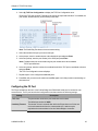
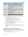
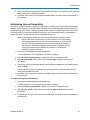
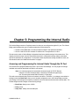
Cellular Bridge
CB-900-V
CB-2.4-V
CB-900-SM
CB-2.4-SM
User Manual
Part Number: LUM0053AA
Revision: C
Last Updated: 10/08/2012
Safety Information
The products described in this manual can fail in a variety of modes due to misuse, age, or malfunction. Systems
with these products must be designed to prevent personal injury and property damage during product operation
and in the event of product failure.
Warning! Do not remove or insert diagnostics cable while circuit is live unless the area is
known to be free of ignition concentrations of flammable gases or vapors.
Warranty
FreeWave Technologies, Inc. warrants your FreeWave® Cellular Bridge against defects in materials and
manufacturing for a period of two years from the date of shipment. In the event of a Product failure due to materials
or workmanship, FreeWave will, at its option, repair or replace the Product. The Product must be returned to
FreeWave upon receiving a Return Material Authorization (RMA) for evaluation of Warranty Coverage.
In no event will FreeWave Technologies, Inc., its suppliers, and its licensors be liable for any damages arising from
the use of or inability to use this Product. This includes business interruption, loss of business information, or other
loss which may arise from the use of this Product. Please be advised that OEM customer’s warranty periods may
vary.
Warranty Policy may not apply:
1. If Product repair, adjustments or parts replacements is required due to accident, neglect, unusual
physical, electrical or electromagnetic stress.
2. If Product is used outside of FreeWave specifications.
3. If Product has been modified, repaired, or altered by Customer unless FreeWave specifically authorized
such alterations in each instance in writing. This includes the addition of conformal coating.
FreeWave Technologies, Inc. makes no warranties with respect to hardware or software provided by third parties
and shall not be liable or responsible for the failure of the third party to perform under or honor any warranty with
respect to hardware or software provided by the third party.
Special Rate Replacement Option
The Special Rate Replacement Option is not applicable to any Cellular Bridge model.
Restricted Rights
Any product names mentioned in this manual may be trademarks or registered trademarks of their respective
companies and are hereby acknowledged. Information in this manual is subject to change without notice and is
proprietary and confidential to FreeWave Technologies, Inc.
This manual is for use by purchasers and other authorized users of FreeWave® transceivers.
No part of this manual may be reproduced or transmitted in any form or by any means, electronic or mechanical, or
for any purpose without the express written permission of FreeWave Technologies, Inc. FreeWave reserves the
right to make changes to this manual without notice. Unless otherwise agreed to in writing, FreeWave assumes no
responsibility or liability for the use of this manual or the infringement of any copyright or other proprietary
right. FreeWave shall deem nothing contained in this manual as warranty or guarantee.
FreeWave's Wireless Data Transceivers are designed and manufactured in the United States of America.
FreeWave Technologies, Inc.
1800 South Flatiron Court
Boulder, CO 80301
303.381.9200
Toll Free: 1.866.923.6168
Printed in the United States of America.
Copyright © 2012 by FreeWave Technologies, Inc. All rights reserved.
LUM0053AA Rev C
Fax: 303.786.9948
www.freewave.com
ii
This product is licensed by The United States. Diversion contrary to U.S. law is prohibited. Export or re-export
of this product outside of The United States may require authorization by the U.S. Bureau of Industry and
Security. Please contact FreeWave Technologies, Inc. for assistance and further information.
UL Notifications
UL approval for models CB-900-V, CB-2.4-V, CB-900-SM, and CB-2.4-SM is currently pending.
LUM0053AA Rev C
iii
General Notifications
l
The Cellular Bridge must be used in accordance with the stated guidelines in this manual.
l
Only approved accessories and antennas may be used with this product.
FCC Notifications
This device complies with part 15 of the FCC rules. Operation is subject to the following two conditions: 1) This
device may not cause harmful interference and 2) this device must accept any interference received, including
interference that may cause undesired operation.
This device must be operated as supplied by FreeWave Technologies, Inc. Any changes or modifications made to
the device without the express written approval of FreeWave Technologies, Inc. may void the user's authority to
operate the device.
This device requires professional installation.
Warning! The CB-900-V and CB-900-SM models have a maximum transmit output power
of 1 Watt. It is recommended that the transmit antenna be kept at least 23 cm away from
nearby persons to satisfy FCC RF requirements.
The data radio antenna and the PCS antennas must be installed 20 cm or greater apart
from one another.
Warning! The CB-2.4-V and CB-2.4-SM models have a maximum transmit output power of
500 mW. It is recommended that the transmit antenna be kept at least 20 cm away from
nearby persons to satisfy FCC RF exposure requirements.
The data radio antenna and the PCS antennas must be installed 20 cm or greater apart
from one another.
Whenever any FreeWave Technologies, Inc. module is placed inside an enclosure, a label must be placed on the
outside of the enclosure. The label must include the text "Contains: FCC ID" (with the module's FCC ID number).
IC Notifications
This device complies with Industry Canada licence-exempt RSS standard(s). Operation is subject to the following
two conditions: (1) this device may not cause interference, and (2) this device must accept any interference,
including interference that may cause undesired operation of the device.
l
This product requires installation in a controlled environment.
l
The data radio antenna and the PCS antennas must be installed 20cm or greater apart from each
other.
Warning! While this product is in use, humans must remain at least 23cm from both
transmit antennas (more information regarding Canadian RF exposure and compliance
(RSS-102) can be found at www.ic.gc.ca)
Ce dispositif est conforme aux normes permis-exemptes du Canada RSS d'industrie. L'opération est sujette aux
deux conditions suivantes : (1) ce dispositif peut ne pas causer l'interférence, et (2) ce dispositif doit accepter
n'importe quelle interférence, y compris l'interférence qui peut causer le fonctionnement peu désiré du dispositif.
LUM0053AA Rev C
iv
Document Revision History
Date
Rev Letter
10/08/2012
C
09/04/2012
08/09/2012
LUM0053AA Rev C
B
A
Updates Made
l
Updated references to the Verizon Data Activation Center to Data
Activation Center. The personnel at the Data Activation Center can
assist with all units and cellular tower locations, not just those for
Verizon.
l
Updated step 8 in "Installing the Internal Radio Firmware Upgrade File"
on page 30 to indicate that the High Speed download option is not
available.
l
Added "Additional Cellular Bridge Components" on page 38.
l
Updated "Indicating Which Devices Can Access a Cellular Bridge" on
page 23 to include information about defining an IP address range within
a network.
l
Updated "Maintaining Internet Connectivity" on page 25 to include
information about the background pinging that keeps the Cellular Bridge
on a cell tower's priority list.
l
Updated step 3 in "Installing the Internal Radio Firmware Upgrade File"
on page 30 to clearly indicate that you must unplug the Cellular Bridge
prior to clicking Disconnect.
l
Updated "Running Diagnostics" on page 34 and "Running Network
Diagnostics Through the P1 Port" on page 35 to indicate there is a 3
minute inactivity timeout when in Diagnostics mode.
Initial release.
v
LUM0053AA Rev C
vi
Table Of Contents
Preface
Chapter 1: Introduction
ix
1
Getting to Know the Cellular Bridge
2
Cellular Bridge LEDs
3
Internal Radio LEDs
4
Powering the Cellular Bridge
4
Configuration Tool Options
5
Using Tool Suite's Setup Terminal to Connect to and Configure a Cellular Bridge
5
Connecting and Disconnecting from Tool Suite
7
Using HyperTerminal to Connect to and Configure a Cellular Bridge
7
Connecting and Disconnecting from HyperTerminal
Startup Sequence
Chapter 2: Activating Verizon Cellular Bridge Models
10
10
13
Activating Verizon Cellular Bridges
13
Verizon Cellular Connection Information
14
Updating the Cell Modem PRL File
15
Accessing the Internet Through the Verizon Cell Network
15
Chapter 3: Activating SIM-Based Cellular Bridge Models
17
Activating SIM-based Cellular Bridges
17
SIM-Based Connection Information
18
Accessing the Internet Through the Cell Network
19
Chapter 4: TCP/IP Port Setup
21
Setting the TCP/IP Port Assignments
21
Configuring the P2 Port
22
Indicating Which Devices Can Access a Cellular Bridge
23
Maintaining Internet Connectivity
25
Chapter 5: Programming the Internal Radio
27
Accessing and Programming the Internal Radio Through the P1 Port
27
Accessing the Internal Radio Remotely
28
Upgrading Internal Radio Firmware
29
Before You Upgrade the Internal Firmware
29
Installing the Internal Radio Firmware Upgrade File
30
Chapter 6: Viewing Cell Bridge Status and Statistics
Available Statistics
LUM0053AA Rev C
33
33
vii
Data Socket Connection
33
Data Socket State
33
Device Current IP
33
Last Data Socket Peer IP
33
Total Bytes Sent from Radio
34
Total Bytes Sent to Radio
34
Total Data Socket Connections
34
Uptime
34
Running Diagnostics
34
Running Network Diagnostics Through the P1 Port
35
Running Network Diagnostics Through the Remote Diag Port
35
Chapter 7: Additional Information
37
Restoring Factory Default Settings
37
Upgrading Cell Modem Firmware
37
Additional Cellular Bridge Components
38
CB-900-V and CB-900-SM Specifications
39
CB-2.4-V and CB-2.4-SM Specifications
40
Glossary
LUM0053AA Rev C
41
viii
Preface
This document includes information about the following regarding the FreeWave Cellular Bridge models:
l
The Cellular Bridge front and back panel components.
l
Activating the Cellular Bridge with the cellular network.
l
Enabling and configuring the TCP ports.
l
Programming the internal radio.
l
Viewing status and statistics.
l
Specifications for each model.
Notational Conventions
This guide uses the following notational conventions:
l
l
l
Bold - Indicates items that you select, parameter settings, and parameter names.
Warning! - Indicates a situation that might cause damage to your radio, data, or network.
- Provides time saving or informative suggestions about using the product.
The term "radio" and "transceiver" are used throughout this manual to refer to the FreeWave transceiver
available within the Cellular Bridge.
LUM0053AA Rev C
ix
Preface
Contacting FreeWave Technical Support
For up-to-date troubleshooting information, check the Support page at www.freewave.com.
FreeWave provides technical support Monday through Friday, 7:30 AM to 5:30 PM Mountain Time (GMT -7).
Call toll-free at 1.866.923.6168, within Colorado call 303.381.9200, or contact us through email at
[email protected].
Documentation Feedback
Your feedback is important to us! FreeWave Technologies, Inc. is committed to continually improving the
quality of our documentation. If you have any comments or suggestions about this document, send them to us
at [email protected]. Please include the title of the document or the document's part number in your
email.
Additional Information
The Cellular Bridge contains a FreeWave transceiver that you can configure through the P1 port. For more
information about how to access and program the transceiver within the Cellular Bridge, see "Programming
the Internal Radio" on page 27. For information about the settings available, see the following user manuals:
l
FGR2 Wireless Data Transceivers User Manual and Reference Guide for CB-900-V and
CB-900-SM models.
l
GX Serial Wireless Data Transceivers User Manual and Reference Guide for CB-2.4-V and
CB-2.4-SM models.
All FreeWave documentation is available on the User Manual and System Tools CD and at
www.freewave.com.
LUM0053AA Rev C
x
Chapter 1: Introduction
The FreeWave Cellular Bridge combines the access and connectivity of cellular networks with the long-range
wireless performance of FreeWave's industrial radios, providing cost affective access to SCADA networks
worldwide. The basic application allows for the consolidation of a radio network into the cellular public
infrastructure.
The Cellular Bridge is available on Verizon and subscriber identification module (SIM)-based networks Models
are available that support 900 MHz or 2.4 GHz:
Cellular Networks and Available Cellular Bridge Models
Verizon
900 MHz Model: CB-900-V
SIM-Based Networks
Model: CB-900-SM
Contains a cell modem that communicates with Contains a cell modem that communicates with
the Verizon cellular network and includes a
SIM-based cellular networks such as AT&T,
FreeWave FGR2-T transceiver.
T-Mobile, and Telstra and includes a FreeWave
FGR2-T transceiver.
2.4 GHz Model: CB-2.4-V
LUM0053AA Rev C
Model: CB-2.4-SM
1
Chapter 1: Introduction
Cellular Networks and Available Cellular Bridge Models
Verizon
SIM-Based Networks
Contains a cell modem that communicates with Contains a cell modem that communicates with
the Verizon cellular network and includes a
SIM-based cellular networks such as AT&T, TFreeWave GX-T transceiver.
Mobile, and Telstra and includes a FreeWave
GX-T transceiver.
A Cellular Bridge is set up as a MultiPoint Master radio in your network.
Getting to Know the Cellular Bridge
The Cellular Bridge contains a cellular modem for communication with a cellular network and a FreeWave
transceiver. The Cellular Bridge's front panel contains LEDs and ports for both components:
l
A serial port for device configuration and diagnostics.
l
A serial port for connection to an external, RS232 or RS484 device.
l
LEDs that indicate power, strength of the cell signal, Internet connectivity status, and activity
between the cell modem and the FreeWave radio. More information about each LED is provided in
"Cellular Bridge LEDs" on the facing page
l
FreeWave transceiver LEDs that indicate when data is being set from or received by the
transceiver, as well as the transceiver's state.
The Cellular Bridge rear panel contains the following components:
l
A power connector.
l
Cellular antenna (SMA).
l
Radio antenna (TNC).
l
SIM card slot (in CB-900-SM and CB-2.4-SM models) (not pictured).
LUM0053AA Rev C
2
Cellular Bridge
Cellular Bridge LEDs
The front panel of each Cellular Bridge model contains a set of LEDs that provide the status and connection
information about the cell modem, and the standard FreeWave radio LEDs that provide status and connection
information about the internal radio.
When the Cellular Bridge is powered on, the left group of LEDs light in sequence from left to right as the
device powers up and goes through its setup sequence. For more information, see "Startup Sequence" on
page 10.
LED
Full Name
Description
PWR
Power
Displays solid green
SIG
Cell Signal
Indicates that the Cellular Bridge connected to the cell carrier's network
at startup and received a signal. The LED is in one of the following
states:
l
l
when the device is connected to power.
Solid bright green - Connected to the cell network with a strong
signal.
Blinking green - Connected to the cell network with a weak signal.
Off - Not connected to the cell network.
The SIG LED state is based on the first tower the device connects to
and is not an active signal light. If the device is roaming, it could connect
to a cell tower at start up and then later acquire a better signal. Power
cycle the device to refresh the LED state based on the most recent cell
tower to which it has connected.
l
MDM
Modem
LUM0053AA Rev C
Displays solid green
when the cell modem has connected through the
cell carrier to the Internet. If the Cellular Bridge is not activated with the
cell carrier network, this LED remains off
.
3
Chapter 1: Introduction
LED
Full Name
Description
SKT
Socket
Displays solid green
when the socket is opened between a device,
such as a polling host, and the cell modem. If the modem has not
established an Internet connection, the socket cannot open and this LED
remains off
.
ACT
Activity
Blinks green
when data is being transferred across an open socket.
When data is not being transferred, the LED remains off
.
CD
Carrier Detect
TX
Transmit
The FreeWave LEDs. The state of the three LEDs indicates the state of
the radio and its ability to send or receive data. For more information, see
the operation LED sections below.
CTS
Clear to Send
Internal Radio LEDs
A Cellular Bridge is set up as a MultiPoint Master radio in your network. The LEDs indicate the current state of
the internal radio.
Master
Condition
Carrier
Detect
(CD)
Transmit
(Tx)
Clear to
Send
(CTS)
Powered, not linked
Solid red bright
Solid red dim
Off
Repeater and Slave linked to Master, no data
Solid red bright
Solid red dim
Off
Repeater and Slave linked to Master, Master sending data to
Slave
Solid red bright
Solid red dim
Off
Solid red dim
Intermittent flash red
Solid red dim
Intermittent flash red
Repeater and Slave linked to Master, Slave sending data to
Master
Master with diagnostics program running
* in an idle condition, the CTS LED is solid red
Solid green
RCV data
or
Solid red bright
Solid red bright
with a solid link, as the link weakens the CTS LED on the
Repeater and Slave begins to blink
Powering the Cellular Bridge
To provide power to the Cellular Bridge, connect it to a positive supply with +12.0 VDC to +24.0 VDC. A
minimum 1.5 Amp power supply is required; however, FreeWave recommends using a 3 Amp power supply
for optimal performance.
Note: Cellular Bridge power supplies are sold separately and are available for
purchase from FreeWave (part number: EMD1230FX).
The power supply you use must provide more current than the amount of current drain listed in the "CB-900-V
and CB-900-SM Specifications" on page 39 and "CB-2.4-V and CB-2.4-SM Specifications" on page 40 for the
voltage you are using. For example, if you are using +12.0 VDC, the power supply must provide current
capability greater than the drain that is required for transmit as listed in the specifications.
LUM0053AA Rev C
4
Cellular Bridge
If the power supply line runs outside the enclosure, use electrostatic discharge (ESD) protectors to protect the
radio from electric shock, and transient voltage suppressors (TVS) to protect from an over-voltage situation.
Using both helps to ensure long-term, reliable operation. FreeWave does not supply these items; however,
they can be purchased at most electronic supply stores.
Configuration Tool Options
To read the current settings from or to program the Cellular Bridge, the device must be in Configuration mode.
Configuration mode provides access to activation and configuration parameters for the cellular settings and
the internal radio. Use one of the following tools to access the Configuration menu:
l
Setup Terminal within Tool Suite - Tool Suite provides a group of tools for configuring the
devices in your network and for monitoring your network's performance. The Setup Terminal
application within Tool Suite is a terminal emulator. You can use this interface to program changes
to the Cellular Bridge settings when connected to device through the P1 port. Tool Suite is
available on the User Manual and System Tools CD and is also available for download from
www.freewave.com.
Note: The Cellular Bridge models are not configurable through the Configuration
application within Tool Suite at this time.
l
HyperTerminal or a terminal emulator of your choice - HyperTerminal is an emulation
program that is provided with earlier versions of Windows. If you run versions of the Windows
operating system prior to Windows 7, HyperTerminal is included in the operating system
installation. However, if you are running Windows 7 or newer, HyperTerminal is no longer
available. The Setup Terminal application within Tool Suite provides the same interface that is
available using HyperTerminal or other terminal emulators.
You may use any other a terminal emulator of your choice. The terminal emulator examples in this
manual are provided using HyperTerminal.
Using Tool Suite's Setup Terminal to Connect to and Configure a Cellular Bridge
To read and program both the cellular settings and the radio settings using the Setup Terminal application in
Tool Suite, you need to connect the Cellular Bridge to a computer that runs the Tool Suite software.
Tool Suite is available on the User Manuals and System Tools CD or at www.freewave.com.
1. Connect a serial cable between the computer or laptop and the P1 connector on the front panel of
the Cellular Bridge and connect the power supply.
2. With the Cellular Bridge connected to the computer, within Tool Suite, click Setup Terminal in the
Application pane to display the Setup Terminal application.
LUM0053AA Rev C
5
Chapter 1: Introduction
3. Ensure the computer port to which the serial cable is connected is selected in the Com Port field
in the Setup Terminal ribbon.
4. Click Connect and type 700 at the cursor prompt to display the Cellular Bridge Main Configuration
menu.
If the device is already up and running, it disconnects from the cell network and closes any open
socket connections before entering Configuration Mode. The Main Configuration menu displays.
LUM0053AA Rev C
6
Cellular Bridge
All three FreeWave LEDs on the Cellular Bridge light green
Cellular Bridge is in Configuration mode.
and stay green as long as the
As you navigate through the Configuration menu and make changes to the parameters, the
parameters are sent to the device as you exit each menu or on exit from the Main Configuration
menu. Changes to the Internal radio settings are sent to the radio immediately.
5. When you are finished making changes, press Esc until you exit the Main Configuration menu .
Connecting and Disconnecting from Tool Suite
The Setup Terminal application within Tool Suite displays two buttons in the Setup Terminal ribbon. To
reconnect a transceiver to the Setup Terminal, you need to disconnect your current session. Click the
Disconnect button, and then click the Connect button to reconnect.
Using HyperTerminal to Connect to and Configure a Cellular Bridge
Note: The screen shots in the following sections represent HyperTerminal in Windows
XP. The display may vary slightly if you are using a different operating system.
1. Click the Windows Start button and select Programs > Accessories > Communications, and
then HyperTerminal.
A window similar to the following displays:
LUM0053AA Rev C
7
Chapter 1: Introduction
2. Double-click the Hypertrm.exe icon.
The following window displays:
3. In the Name field, enter a descriptive name for the connection and select an icon from the Icon
selection box.
4. Click OK.
The Connect To dialog box displays.
5. In the Connect Using field, select the connection type to use.
Select the active Com Port to which the radio is connected. In most cases the connection type will
be either Direct to Com1 or Direct to COM2.
6. Click OK.
LUM0053AA Rev C
8
Cellular Bridge
The Properties dialog box displays for the selected connection type.
Enter the following port settings for a proper connection:
Port Setting
Select
Bits per second
19200
Data bits
8
Parity
None
Stop bits
1
Flow control
None
7. After selecting the option for each setting, click OK.
The following HyperTerminal dialog box displays:
LUM0053AA Rev C
9
Chapter 1: Introduction
8. From the File menu, select Save to save the HyperTerminal connection settings.
Important: To make changes to the connection properties, you must first disconnect
the terminal session.
9. To connect HyperTerminal to the Cellular Bridge, connect the power supply to the Cellular Bridge
and connect a serial cable from the P1 connector on the front of the Cellular Bridge to the computer
running the HyperTerminal session.
10. Within HyperTerminal, type 700 to display the Main Configuration menu.
If the device is already up and running, it disconnects from the cell network and closes any open
socket connections before entering Configuration Mode. The Main Configuration menu displays.
The Main Configuration menu displays in the HyperTerminal dialog box. All three FreeWave LEDs
on the Cellular Bridge light green
and stay green as long as the Cellular Bridge is in
Configuration mode.
As you navigate through the Configuration menu and make changes to the parameters, the
parameters are sent to the device as you exit each menu or on exit from the Main Configuration
menu. Changes to the Internal radio settings are sent to the radio immediately.
11. When you are finished making changes, press Esc until you exit the Main Configuration menu.
Connecting and Disconnecting from HyperTerminal
The HyperTerminal dialog box displays several icons in the toolbar. To reconnect to HyperTerminal, you need
to disconnect your current session. Click the Disconnect
icon, and then click the Call
icon to
reconnect. If the settings have not been saved they must be re-selected when HyperTerminal reconnects to
the transceiver.
Startup Sequence
When you have a Setup Terminal or any terminal emulator directly connected to the Cellular Bridge P1 port,
when the device starts up it provides information about the following:
l
Whether it is registered with the cell network and whether it is connected to the home network.
l
The signal strength. -90 dBm or better is considered a strong signal.
l
The device IP address.
LUM0053AA Rev C
10
Cellular Bridge
l
Each TCP port and its assigned port number.
l
If any other device in the network is attempting to connect to the device.
In addition, the cell modem LEDs on the front panel provide information about the successful completion of
the startup sequence. Each LED illuminates in sequence from left to right as the device goes through the
startup process.
l
Power LED - Illuminates when power is supplied to the Cellular Bridge. This LED remains lit as
long as power is supplied to the device.
l
SIG - Illuminates when the Cellular Bridge has made contact with a cell tower and has a signal. If
the device is not activated, this LED and any subsequent LEDs do not illuminate. The SIG LED
state is based on the first tower the device connects to and is not an active signal light.
l
MDM - Illuminates when the Cellular Bridge has established an Internet connection through the cell
carrier.
l
SKT - Illuminates when a socket is opened between a device, such as a polling host, and the cell
modem.
l
ACT - This LED only lights when data is being transferred across an open socket and is not part of
the startup sequence.
LUM0053AA Rev C
11
LUM0053AA Rev C
12
Chapter 2: Activating Verizon
Cellular Bridge Models
When you purchase a CB-900-V or CB-2.4-SM, you must activate it with Verizon prior to use. FreeWave
recommends activating and testing each Cellular Bridge at your office location prior to taking the device to the
field to install it.
Important: Each Cellular Bridge requires a static IP address. Regardless of the
Verizon model type, when you activate the device, Verizon assigns the device a static
Internet IP address. Because the device requires a static IP address, it can take one to
three business days for the cellular carrier to complete the device activation.
Activating a Verizon Cellular Bridge and a SIM-based Cellular Bridge varies slightly. Instructions to activate a
SIM-based Cellular Bridge are provided in the next chapter.
Activating Verizon Cellular Bridges
You must request activate each CB-900-V and CB-2.4-V Cellular Bridge with Verizon prior to use. Activating
the device indicates to Verizon that the device is valid on their network, provides the device with its phone
number, and loads the Preferred Roaming List (PRL) version. The PRL includes the list of cell towers to which
the Cellular Bridge can connect.
Prior to activating a Verizon Cellular Bridge:
l
Note the ESN number located on the outside label of the device. The ESN is unique to the device,
much like a serial number. You must have this number to complete activation with Verizon.
You can also find the ESN number on the Cellular Configuration menu when the device is in
Configuration mode. For more information about accessing the configuration settings, see
"Configuration Tool Options" on page 5.
LUM0053AA Rev C
13
Chapter 2: Activating Verizon Cellular Bridge Models
l
Ensure that you are within the cell carrier's coverage area. Coverage maps are available on most
carriers' Web sites. The Cellular Bridge must be connected to a Verizon cell tower, and not
connected to a roaming partner's tower for activation. Representatives at the Data Activation
Center (866-966-8881) can assist you in locating a Verizon cell tower.
l
Verify that you have a strong cell signal at your location. FreeWave recommends a signal strength
of -100 dBm or better to activate a Cellular Bridge.
l
Ensure that the cell and radio antennas are attached to the Cellular Bridge before powering the
Cellular Bridge.
When you have completed the above, you are ready to activate the Cellular Bridge.
1. With the ESN noted, call the Data Activation Center at 866-966-8881.
Note: Do not take the Cellular Bridge to a Verizon store for activation.
The Verizon representative asks you for the ESN plus additional information such as name and
address for billing purposes, similar to the information required to activate a cell phone.
2. After one to three business days, access the device's configuration Main Menu.
For more information, see "Configuration Tool Options" on page 5.
3. From the Main Configuration menu, select (3) Cellular Connection Configuration to display the
Cellular Modem Configuration menu.
4. Select (1) Activate CDMA Modem and enter Y at the prompt to continue with the activation.
Once initiated, the activation process can take up to three minutes to complete. Ensure that the
device has power through the entire activation process. The Cellular Bridge connects with the cell
network, verifies the ESN has been activated, and acquires its phone number, MIN/MSI numbers,
and the PRL version. For more information, see "Verizon Cellular Connection Information" below
When the activation has completed, a message displays indicating that the attempt to connect
was successful.
5. To verify the activation, press any key to redisplay the Cellular Modem Configuration menu.
If the activation was successful, the device now has an assigned phone number, MIN/MSI
number, and an updated PRL version listed in the header information in the Cellular Modem
Configuration menu.
Verizon Cellular Connection Information
The Cellular Modem Configuration Menu (option 3 in the Main Configuration menu) provides information
regarding the Cellular Bridge and its current connection to the cell network.
The following information displays at the top of the Cellular Modem Configuration menu:
Field
Description
Type
The cell modem type installed in the Cellular Bridge.
Service Provider
Indicates the current cell service provided with which the Cellular Bridge is
registered.
LUM0053AA Rev C
14
Cellular Bridge
Field
Description
ESN
The electronic serial number that uniquely identifies the cell modem in the
Cellular Bridge to Verizon. You must have this number to activate the
device with Verizon.
Phone Number
The device's telephone number. This number is assigned when you
activate the Cellular Bridge.
MIN/MSI
The mobile identification number (MIN), or mobile subscriber identity (MSI).
This number is assigned when you activate the Cellular Bridge
PRL Version
The version of the Primary Roaming Locations (PRL) file installed. This file
contains a list of the cell towers to which the device is approved to connect.
Modem Registration
Indicates if the modem is currently registered and connected to the cell
network, and whether it is connected to the home network or is roaming.
Signal (RSSI)
The received signal power from the cellular network. This is the received
signal from the first tower the cell modem hears at power up and is not a
real-time signal reading.
Updating the Cell Modem PRL File
When you activate a Cellular Bridge, it downloads a Primary Roaming Locations (PRL) file that contains the
list of cell towers to which the device is approved to connect. You can update this file as additional towers are
installed in the operating area.
Prior to updating the file, verify that you have a strong cell signal at your location. FreeWave recommends a
signal strength of -100 dBm or better.
1. Access the Cellular Bridge Main Configuration menu.
For more information, see "Configuration Tool Options" on page 5.
2. Select (3) Cellular Connection Configuration to display the Cellular Modem Configuration
menu.
3. Select (7) Update Modem PRL and enter Y at the prompt to continue.
If the Cellular Bridge has a strong enough signal, it downloads and installs the latest PRL file
available from the cell carrier. If the signal is too weak, it displays a message indicating that the
signal is not strong enough to complete the update. Press any key to return to the Cellular Modem
Configuration menu.
After a successful update, the new PRL version number displays in the PRL Version field in the
Cellular Configuration Menu's header information.
Accessing the Internet Through the Verizon Cell Network
To access the Internet through the cell carrier's network, the device must know the code to dial and the user
name and password associated with the device. When you activate a Verizon-based Cellular Bridge, the dial
number and a default username and password are assigned.
1. Access the Cellular Bridge Main Configuration menu.
For more information, see "Configuration Tool Options" on page 5.
LUM0053AA Rev C
15
Chapter 2: Activating Verizon Cellular Bridge Models
2. Select (3) Cellular Connection Configuration to display the Cellular Modem Configuration
menu.
3. In CB-900-V and CB-2.4-V models, ensure the Dial Number is set to #777.
This dial number determines how the device connects to the Internet through the cell carrier's
network and should not be changed.
4. If the Dial Number is not set to #777, select (2) Dial Number, enter the appropriate number for
the cell carrier, and press Enter.
The dial number is not a standard phone number. Do not enter the Cellular Bridge's assigned
phone number in this field.
5. To change the username or password, select (3) Username or (4) Password, enter the username
or password at the prompt, and press Enter.
Verizon does not require a username and password to access the Internet at this time.
6. Press Esc until you return to the main menu and Esc again to exit Setup mode to send settings to
the transceiver.
LUM0053AA Rev C
16
Chapter 3: Activating SIM-Based
Cellular Bridge Models
The Cellular Bridge supports cellular carriers such as AT&T, T-Mobile, Telus, and more and contains an
embedded SIM-based HSPA/GSM/GPRS/EDGE modem.
When you purchase a Cellular Bridge, you must activate it with the appropriate cellular network prior to use.
FreeWave recommends activating and testing each Cellular Bridge at your office location prior to taking the
device to the field to install it.
Note: Activating a SIM-based Cellular Bridge and a Verizon d Cellular Bridge varies
slightly. Instructions to activate a Verizon Cellular Bridge are provided in the
previous chapter.
Activating SIM-based Cellular Bridges
Activating the CB-900-SM and CB-2.4-SM Cellular Bridge models is done using the SIM card. The SIM card
itself is activated with the carrier you choose.
Prior to activating a SIM-based Cellular Bridge:
l
Obtain an account and a SIM card enabled for data services from the cellular carrier.
Some cellular carriers require the International Mobile Equipment Identity (IMEI) number of the
Cellular Bridge before they provide or activate a SIM card. The IMEI number of the embedded
cellular modem is printed on the label on the outside of the Cellular Bridge. You can also find the
IMEI number on the Cellular Configuration menu when the device is in Configuration mode. For
more information about access the configuration settings, see "Configuration Tool Options" on
page 5.
l
Note the Access Point Name (APN) of the cellular carrier. APNs apply to GPRS/EDGE cellular
networks.
LUM0053AA Rev C
17
Chapter 3: Activating SIM-Based Cellular Bridge Models
l
Note the SIM personal identification number (PIN), if required for the cellular carrier. SIM PINs
apply to GSM/GPRS/EDGE cellular networks.
l
Ensure that you are within the cell carrier's coverage area. Coverage maps are available on most
carriers' Web sites.
l
Verify that you have a strong cell signal at your location. FreeWave recommends a signal strength
of -100 dBm or better to activate a Cellular Bridge.
l
Ensure that the cell radio antennas are attached to the Cellular Bridge and that the SIM card is
inserted before powering the Cellular Bridge.
When you have completed the above, you are ready to activate the Cellular Bridge.
1. Insert the activated SIM card for the cellular carrier into the SIM card slot in the Cellular Bridge and
connect the device to power.
Warning! Do not insert or remove a SIM card from a Cellular Bridge that is connected
to and receiving power. Inserting and removing a SIM card from a powered Cellular
Bridge can result in damage to the Cellular Bridge and the SIM card itself.
2. Access the Cellular Bridge Main Configuration menu.
For more information, see "Configuration Tool Options" on page 5.
3. From the Main Configuration menu, select (3) Cellular Connection Configuration to display the
Cellular Modem Configuration menu.
4. Select (5) APN, enter the APN for the cellular carrier, and press Enter.
The APN identifies to which networks the Cellular Bridge can connect. The APN is unique to each
carrier and is case-sensitive. The cellular carrier provides the APN name to you when you activate
the SIM card for the device.
5. If the SIM card requires a PIN, select (6) SIM PIN, enable the setting, enter the PIN, and press
Enter.
6. Press Esc until you return to the main menu and Esc again to exit Configuration mode.
SIM-Based Connection Information
The Cellular Modem Configuration Menu (option 3 in the Main Configuration menu) provides information
regarding the Cellular Bridge and its current connection to the cell network.
The following information displays at the top of the Cellular Modem Configuration menu:
Field
Description
Type
The cell modem type installed in the Cellular Bridge.
Service Provider
Indicates the current cell service provided with which the Cellular Bridge is
registered.
IMEI
The International Mobil Equipment Identity (IMEI) number that uniquely
identifies the cellular modem in the Cellular Bridge to a GSM cellular
network. The IMEI identifies the device only and has no relation to the
subscriber of the device.
LUM0053AA Rev C
18
Cellular Bridge
Field
Description
SIM Card IMSI/ICCID
International Mobile Equipment Identity (IMSI) and the integrated circuit
card identifier (ICCID) are two numbers that identify the SIM card to the
cellular network.
Phone Number
The device's telephone number. This number is assigned when you
activate the Cellular Bridge.
Modem Registration
Indicates if the modem is currently registered and connected to the cell network, and whether it is connected to the home network or is roaming.
Signal (RSSI)
The received signal power from the cellular network. This is the received
signal from the first tower the cell modem hears at power up and is not a
real-time signal reading.
Accessing the Internet Through the Cell Network
To access the Internet through the cell carrier's network, the device must know the number to dial, its
preferred cell provider and the user name and password associated with the device. For SIM-based Cellular
Bridge, you must enter the dial number, username, and password as they are unique to each cell carrier.
Some cell carriers require a username and password to activate the Cellular Bridge.
1. Access the Cellular Bridge Main Configuration menu.
For more information, see "Configuration Tool Options" on page 5.
2. Select (3) Cellular Connection Configuration to display the Cellular Modem Configuration
menu.
3. Select (1) Rate Preference and select the cellular network data transmission standard that you
prefer to use at the Cellular Bridge:
l
(0) Auto - Enables the cell modem to use the cell carrier's default data transmission standard.
This is the default.
l
(1) 3G Only - Uses only the 3G rate, even when different rates are available.
l
(2) 2G Only - Uses only the 2G rate, even when different rates are available.
l
(3) 3G Pref - Uses the 3G rate when it is available, and 2G when 3G is not available.
l
(4) 2G Pref - Uses the 2G rate when it is available, and 3G when 2G is not available.
4. Ensure the Dial Number is set to the correct number corresponding to the cell carrier you are
using.
This dial number determines how the device connects to the Internet through the cell carrier's
network and should not be changed. For packet switched data services, this number is prepopulated depending on the cellular carrier. For example, for GPRS/EDGE carriers such as AT&T,
the number is *99***1#.
5. If the Dial Number is not set correctly, select (2) Dial Number, enter the appropriate number for
the cell carrier, and press Enter.
The dial number is not a standard phone number. Do not enter the Cellular Bridge's assigned
phone number in this field. Contact your cell carrier for the dial number, if necessary.
LUM0053AA Rev C
19
Chapter 3: Activating SIM-Based Cellular Bridge Models
6. To change the username or password, select (3) Username or (4) Password, enter the username
or password at the prompt, and press Enter.
Many cellular carriers require a default username, such as username or - and a password. Check
with your cellular carrier for their requirements including username and password.
7. Press Esc until you return to the main menu and Esc again to exit Setup mode to send settings to
the transceiver.
LUM0053AA Rev C
20
Chapter 4: TCP/IP Port Setup
The Cellular Bridge has the following TCP/IP ports available for configuration using the P1 port on the front
panel.
l
Radio Data Port - The main data port of the internal radio. Provides access to the main data flow
of the Master radio.
l
Radio DIAG Port - The diagnostics port of the internal radio. Provides access to standard
diagnostics through the Master radio.
l
Remote Port - A port that provides access to remotely configure the device.
l
P2 Data Port - The P2 port available on the front panel Cellular Bridge, available to connect
directly to an external RS232 or RS485 device.
You can enable each port through the TCP Port Configuration menu and set the port's number and inactivity
timeout interval. There are additional settings for the P2 data port to configure it to connect to an external
device. For information about setting up this port, see "Configuring the P2 Port" on next page. For information
about configuring the other ports, see "Setting the TCP/IP Port Assignments" below.
Note: The default setting for each port is Disabled.
Setting the TCP/IP Port Assignments
You can enabled or disable each TCP/IP port as needed. In addition, you can change the factory default port
number and set the inactivity timeout for each port. The ports are configurable through the TCP Port
Configuration menu when the Cellular Bridge is in Configuration Mode. Configure the Radio Data, Radio
DIAG, and Remote ports using the instructions below.
For information about configuring the P2 port for connection to an external device, see "Configuring the P2
Port" on next page.
1. Access the Cellular Bridge Main Configuration menu.
For more information, see "Configuration Tool Options" on page 5.
LUM0053AA Rev C
21
Chapter 4: TCP/IP Port Setup
2. Select (2) TCP Port Configuration to display the TCP Port Configuration menu.
Each of the TCP ports is listed. The detail to the right of each port and indicates if it is enabled, the
port number, and the inactivity timeout setting in seconds.
Note: The Radio Diag Port does not have a timeout setting.
3. Select the number of the port you want to configure.
4. At the prompt, enter 1 to enable the port or 0 to disable the port and press Enter.
5. At the next prompt, enter the port number (10 to 65535) and press Enter.
Note: FreeWave does not recommend using low port number due to other standard
TCP/IP port definitions.
6. At the next prompt, enter the number of seconds after which the TCP port is considered to timeout
and press Enter.
The TCP Port Configuration menu redisplays.
7. Repeat steps 3 to 6 to configure the additional ports.
8. Press Esc until you return to the main menu and Esc again to exit Setup mode to send settings to
the transceiver.
Configuring the P2 Port
The P2 port available on the front of the Cellular Bridge is an RS232/485 serial port for connection to an
external device. The P2 port has a limited configuration menu that contains the following settings:
Setting
TCP Port
Description
The port number on which the port sends and receives data.
The default port number is 30002.
Inactivity Timeout
LUM0053AA Rev C
The amount of time in seconds after which the P2 port times out if it has not
received a transmission from the connected device. A reboot may be
required at the connected device for the Cellular Bridge to reconnect.
22
Cellular Bridge
Setting
Baud Rate
Description
The communication rate between the Cellular Bridge P2 port and the
instrument to which it is attached through the port. Set the baud rate to the
highest level supported by the device to which it is connected. With a poor
radio link, this may actually result in slower data communications.
The default setting is 115200.
Possible baud rates include: 1200, 2400, 4800, 9600, 19200, 38400, 57600,
76800, 115200, 230400
HW Flow Control
If enabled, controls the transmission speed to not overwhelm the receiving
device. FreeWave recommends enabling flow control if you are using a baud
rate higher than 19200 on the P2 port.
The default setting is Disabled.
Serial Port Mode
The protocol of the serial port. Possible serial port modes include:
RS232/RS485.
The default setting is RS232.
Parity, Data, Stop
Six data word length and parity configurations are available. The default
setting is None-8-1 and is the most commonly used serial communications
protocol.
1. Access the Cellular Bridge Main Configuration menu.
For more information, see "Configuration Tool Options" on page 5.
2. Select (2) TCP Port Configuration to display the TCP Port Configuration menu.
3. Select (3) P2 Port Configuration to display the P2 Port Configuration menu.
4. Select (1) P2 Port, enter 1 at the prompt, and press Enter to enable the P2 port.
The P2 Port Configuration menu redisplays.
5. Enter the number that corresponds with the parameter setting you would like to change, enter the
correct values at the prompt, and press Enter.
6. Repeat step 5 for each parameter you want to change.
Selecting (7) Parity, Data, Stop, prompts you for the data parity, data bits, and stop bits
consecutively.
7. Press Esc until you return to the main menu and Esc again to exit Setup mode to send settings to
the transceiver.
Indicating Which Devices Can Access a Cellular Bridge
Using the IP Address List, you can restrict which devices have access to the Cellular Bridge. If all the
IP addresses in the list are disabled, any device can access the Cellular Bridge. If the list contains one or
more enabled IP addresses, only the addresses in the list have access to the device. The list can contain up
to four single IP addresses or address ranges.
Note: The IP Address List can contain disabled IP addresses.
LUM0053AA Rev C
23
Chapter 4: TCP/IP Port Setup
To enter a single host IP Address:
1. Access the Cellular Bridge Main Configuration menu.
For more information, see "Configuration Tool Options" on page 5.
2. Select (2) TCP Configuration to display the TCP Configuration Port menu.
3. Select (5) IP Address List to display the IP Access List menu.
4. Select the number that corresponds to the IP address you want to set or enable, enter 1, and press
Enter at the prompt to enable the selection.
5. At the Host or Network Address Prompt, enter 0 and press Enter.
6. At the Enter IP Address prompt, enter the IP address in IPv4 format (0.0.0.0) of the device you
want to grant access, and press Enter.
7. Repeat steps 4 and 5 for the additional addresses you want to enable and provide in the list.
8. Press Esc until you return to the main menu and Esc again to exit Setup mode to send settings to
the transceiver.
To enter a network address range:
1. Access the Cellular Bridge Main Configuration menu.
For more information, see "Configuration Tool Options" on page 5.
2. Select (2) TCP Configuration to display the TCP Configuration Port menu.
3. Select (5) IP Address List to display the IP Access List menu.
4. Select the number that corresponds to the IP address you want to set or enable, enter 1, and press
Enter at the prompt to enable the selection.
5. At the Host or Network Address Prompt, enter 1 and press Enter.
6. At the Enter Mask Bits prompt, enter the network bits (netmask) representing the range of
addresses available in the network that can access the device, and press Enter.
The number of addresses defined by the mask or prefix can be calculated as 232-prefix size. For
example, mask bits of /29 is: 232-29= 23 = 8 addresses.
7. At the Enter IP Address prompt, enter the IP address in IPv4 format (0.0.0.0) and press Enter.
The network address displays with a slash and the network bits. For example, 192.168.0.0,
netmask 255.255.255.0 displays as 192.168.0.0/24.
8. Repeat steps 4 through 7 for the additional addresses you want to enable and provide in the list.
9. Press Esc until you return to the main menu and Esc again to exit Setup mode to send settings to
the transceiver.
To disable an IP address in the access list:
1. Access the Cellular Bridge Main Configuration menu.
For more information, see "Configuration Tool Options" on page 5.
2. Select (2) TCP Configuration to display the TCP Configuration Port menu.
3. Select (5) IP Address List to display the IP Access List menu.
LUM0053AA Rev C
24
Cellular Bridge
4. Select the number that corresponds to the IP address you want to set or disable, enter 0, and press
Enter at the prompt to disable the selection.
5. Press Esc until you return to the main menu and Esc again to exit Setup mode to send settings to
the transceiver.
Maintaining Internet Connectivity
Use the Ping Check functionality to regularly send a request to a Web site to ensure that the Cellular Bridge
maintains its Internet access. If the Ping Check is enabled, the Cellular Bridge sends a request through the
cell network once every minute. If the Cellular Bridge cannot connect, it sends the request every 30 seconds
for several minutes. At the fourth attempt with no response, the Cellular Bridge reboots to re-establish its
Internet connection. The request interval is not configurable at this time.
Note: A cellular device that has not communicated through the cell network regularly
begins to rank lower in priority at the cell tower for access. The Cellular Bridge
sends a background ping to the cell tower to keep the device on the cell tower's
active list. The background ping function occurs automatically and results in
approximately 1 MB of data usage per month and is not configurable. Use the
Ping Check functionality described below to ensure the Cellular Bridge
maintains its Internet connection.
1. Access the Cellular Bridge Main Configuration menu.
For more information, see "Configuration Tool Options" on page 5.
2. Select (2) TCP Port Configuration to display the TCP Port Configuration menu.
3. Select (6) Ping Check, enter 1 at the prompt, and press Enter to enable the Ping Check
functionality.
4. At the Enter Ping Check Hostname prompt, enter the Web site address the cell modem requests
and press Enter.
Choose a Web site such as www.google.com or www.amazon.com that has a long history of
being up and available at all times.
5. Press Esc until you return to the main menu and Esc again to exit Setup mode to send settings to
the transceiver.
To disable the Ping Check functionality:
1. Access the Cellular Bridge Main Configuration menu.
For more information, see "Configuration Tool Options" on page 5.
2. Select (2) TCP Port Configuration to display the TCP Port Configuration menu.
3. Select (6) Ping Check, enter 0 at the prompt, and press Enter to disable the Ping Check
functionality.
4. Press Esc until you return to the main menu and Esc again to exit Setup mode to send settings to
the transceiver.
LUM0053AA Rev C
25
LUM0053AA Rev C
26
Chapter 5: Programming the Internal Radio
The Cellular Bridge contains a FreeWave transceiver that you can configure through the P1 port. The Cellular
Bridge model indicates the type of FreeWave transceiver inside the device:
l
CB-900-V and CB-900-SM - Includes a FreeWave FGR2-T that operates at 900 MHz.
l
CB-2.4-V and CB-2.4-SM - Includes a FreeWave GX-T that operates at 2.4 GHz.
The transceiver inside a Cellular Bridge is shipped with the factory default settings for that transceiver. This
chapter provides the steps to access the internal transceiver's configuration settings and any notes about
special considerations for configuration. For information about the parameter settings available for each, see
the manuals listed in the "Additional Information" on page x
Accessing and Programming the Internal Radio Through the P1 Port
The internal radio is programmable through the P1 port on the Cellular Bridge. You can program all settings
available on the radio as described in the radio's user manual.
Note: You can also program the internal radio remotely through the TCP/IP Remote
Data port. For more information about connecting to the radio through that port,
see "Accessing the Internal Radio Remotely" on next page.
The radio communicates directly with the cell modem in the device. Therefore, if you change communication
settings such as the Baud Rate, when you exit the radio configuration menu, the Cellular Bridge overrides
your settings to the settings that it requires to maintain communication between the modem and the radio. The
Cellular Bridge overrides changes to the following settings:
l
Baud Rate - Always set to 115200.
l
Parity - None
l
Setup Port - Always set to the Main port.
LUM0053AA Rev C
27
Chapter 5: Programming the Internal Radio
The menu allows you to make changes to these settings. When you press Esc to return to the Main
Configuration menu, a message displays that indicates the device is checking for Key Parameter changes.
Note: If you need to make communication setting changes to connect to an external
device, configure the settings on the P2 port. For more information, see
"Configuring the P2 Port" on page 22.
1. Access the Cellular Bridge Main Configuration menu.
For more information, see "Configuration Tool Options" on page 5.
2. From the Main Configuration menu, select (1) Internal Radio Configuration.
3. At the prompt, enter one of the following and press Enter to access the radio's Setup Main menu:
l
0 - To access the radio through its main data port.
l
1- To access the radio through its diagnostic port.
The Setup menu for the installed radio installed displays.
4. Make changes as necessary.
Changes are sent to the radio immediately.
5. Press Esc to return to the Cellular Bridge Main Configuration menu.
Accessing the Internal Radio Remotely
The TCP/IP Remote Data port, if enabled, allows access to the Internal Radio Configuration settings and the
TCP Port Configuration settings through the Internet through the cell carrier, without a physical connection to
the P1 port.
Note: The following access instructions are written for the HyperTerminal emulator.
The instructions can differ slightly for the terminal emulator you are using. Setup
Terminal in Tool Suite requires a physical connection from the computer's Com
port to the Cellular Bridge P1 port and cannot be used to establish a remote
connection.
1. From an open HyperTerminal session, select File > New Connection and name the connection.
2. Click OK to display the Connect To dialog box.
3. In the Host Address field, enter the static IP of the Cellular Bridge to which you want to connect.
4. In the Port field, enter the port number of the Remote Data port of the Cellular Bridge.
For information about the Remote Port and its port number, see "Setting the TCP/IP Port
Assignments" on page 21.
5. In the Connect Using field, select TCP/IP and click OK to establish the connection.
Note: If the internal radio in the Cellular Bridge contains a password, you are required
to enter that password to continue.
If the Cellular Bridge is up and running and available through the cell carrier's Internet network, the
Configuration Menu displays with the Internal Radio Configuration and TCP Port Configuration
options.
LUM0053AA Rev C
28
Cellular Bridge
You can now use these menus as described in "Programming the Internal Radio" on page 27and
"TCP/IP Port Setup" on page 21.
Upgrading Internal Radio Firmware
The internal radio within the Cellular Bridge can be upgraded as needed, just like any FreeWave radio. The
latest version of firmware that is available for the internal radio is installed at the factory prior to shipment.
Upgrading the internal radio firmware does not upgrade the cell modem firmware. The cell modem firmware is
upgraded separately. For more information, see "Upgrading Cell Modem Firmware" on page 37.
Review the information in "Before You Upgrade the Internal Firmware" below before following the instructions
in "Installing the Internal Radio Firmware Upgrade File" on next page
Important: If you are using a USB-to-serial converter cable, a firmware upgrade can
take a long time to complete. FreeWave recommends using only USB-to-serial cables
that include the FTDI Chip Set. This inclusion is listed on the cable's packaging.
Before You Upgrade the Internal Firmware
Before you begin the upgrade process, verify the firmware version that the internal radio is running, that the
radio port is set to the main port, and that the Diagnostics setting is set to 0.
1. Access the Cellular Bridge Main Configuration menu.
For more information, see "Configuration Tool Options" on page 5.
2. Select (1) Internal Radio Configuration to display the Internal Radio Configuration menu.
3. If prompted, enter 0 and press Enter to access the radio through the main data port. The upgrade
must be completed through the main port.
The firmware version currently installed is listed in the top portion of the menu.
4. If you were not prompted to select a port, from the Internal Radio Configuration menu select (1) Set
Baud Rate, select (D) Setup Port, and enter 1 to use the main port for radio setup.
5. Press Esc to return to the Internal Radio Configuration menu and select (5) Show MultiPoint
Parameters.
6. Select (B) Diagnostics, enter 0 to disable Diagnostics, and press Enter.
LUM0053AA Rev C
29
Chapter 5: Programming the Internal Radio
7. Press Esc until you return to the main menu and Esc again to exit Setup mode to send settings to
the transceiver.
In addition, download the correct firmware upgrade file from www.freewave.com. Ensure that you download
the file associated with the correct radio model installed in the Cellular Bridge. For more information, see
"Introduction" on page 1.
Installing the Internal Radio Firmware Upgrade File
After you download the firmware upgrade file, you are ready to install it onto the internal radio within the
Cellular Bridge
1. Access the Cellular Bridge Main Configuration menu.
For more information, see "Configuration Tool Options" on page 5.
2. Select (5) Administration to display the Administration menu and select (2) Upgrade Internal
Radio Firmware.
The Internal Radio Configuration menu displays.
3. Unplug the cable from the Cellular Bridge and then click Disconnect in your terminal session.
The Internal Radio remains in Setup mode.
4. With the Cellular Bridge still connected to the computer, use Windows Explorer to navigate to the
firmware file and double-click the file to launch the upgrade application.
5. Verify that the Com Port and Baud Rate settings at the bottom of the screen match the port and
baud rate you are using to connect the Cellular Bridge to the computer running the upgrade
program.
If they do not match, select 3 and enter the correct port and baud rate at the prompts and press
Enter to return to the main menu.
LUM0053AA Rev C
30
Cellular Bridge
6. At the main menu, select 1, enter N at the prompt to select the data port, and press Enter to start
the upgrade.
7. At the Radio in Setup prompt, if the CD, TX, and CTS LEDs on the front of the Cellular Bridge are
solid green, enter Y and press Enter to continue.
If the LEDs are not solid green, the internal radio is not in Setup mode and cannot receive the
upgrade. For information about placing the radio in Setup mode, see "Accessing and Programming
the Internal Radio Through the P1 Port" on page 27.
8. At the High Speed Download prompt, enter N. The High Speed Download is not available.
The upgrade starts and the screen looks similar to the following as the upgrade runs. As the
upgrade progresses, the screen displays a series of numbers and letters.
When the Program Time displays, the upgrade has finished.
9. Press any key to return to the main menu.
The Version field displays the new firmware version. If the previously installed version still
displays, the upgrade was not successful. Repeat the process or contact FreeWave Technical
Support for assistance.
LUM0053AA Rev C
31
Chapter 5: Programming the Internal Radio
10. Enter Q to escape and then press Esc to exit the upgrade program.
11. Reboot the Cellular Bridge and access the Main Configuration menu as you did in step 1.
LUM0053AA Rev C
32
Chapter 6: Viewing Cell Bridge
Status and Statistics
When you connect to an up and running Cellular Bridge through a terminal emulator, the device displays cell
and data transmission statistics. This information is valuable when you need to know the signal strength and
activity through the Cellular Bridge. In addition, you can view more data transmission characteristics by
running Network Diagnostics using the Network Diagnostics application in Tool Suite.
Available Statistics
When the Cellular Bridge is up and running and is connected to Setup Terminal or another terminal emulator, it
displays the statistics below. The information refreshes approximately every 30 seconds while the device
remains connected.
Data Socket Connection
Indicates if the connection between the cell bridge and the radio is currently active.
Data Socket State
The current state of the connection between the cell bridge and the internal radio, for example, Listen.
Device Current IP
The static IP address assigned to the device.
Last Data Socket Peer IP
The IP address of the device that last connected to the Cellular Bridge through the data socket.
LUM0053AA Rev C
33
Chapter 6: Viewing Cell Bridge Status and Statistics
Total Bytes Sent from Radio
The total amount of data in bytes sent from the internal radio during the device's uptime listed in the Uptime
parameter.
Total Bytes Sent to Radio
The total amount of data in bytes the internal radio has received during the device's uptime listed in the
Uptime parameter.
Total Data Socket Connections
The total number of times a connection was made between the cell bridge and the internal radio during the
device's uptime listed in the Uptime parameter.
Uptime
The total number of hours, minutes, and seconds the device has been connected to the cell network. This
information resets if the device loses its network connection.
Running Diagnostics
Using the internal radio at the Master, you can run diagnostics for the radio network locally through the P1 port
or remotely through the Internet using the TCP/IP Remote DIAG port.
Important: While running diagnostics locally through the P1 port, the radio only
receives diagnostics information. You must exit Diagnostics mode and power cycle
the Cellular Bridge to return the internal radio to a mode where it can receive and send
data.
If the Cellular Bridge does not receive any poll requests from the Diagnostics software
for 3 minutes, it reboots automatically and returns the internal radio to mode where it
can receive and send data.
Radio diagnostics are not readable within Setup Terminal or other terminal emulators. However, use the
emulator to connect to the Cellular Bridge and set it into Diagnostics mode. Then collect diagnostics data in
the Network Diagnostics application within FreeWave's Tool Suite
To set the internal radio to Diagnostics Mode:
1. Access the Cellular Bridge Main Configuration menu.
For more information, see "Configuration Tool Options" on page 5.
2. Select (4) Activate Radio Diagnostics on P1 port and enter Y at the prompt.
The diagnostic data that the internal radio is sending displays at the prompt in a series of random
symbols.
3. Close the terminal window.
You can now connect to the internal radio through the Network Diagnostics application in
Tool Suite to receive and review diagnostic data.
LUM0053AA Rev C
34
Cellular Bridge
To exit Diagnostics mode:
1. Power cycle the device to return to normal operation.
The Cellular Bridge goes through the setup sequence as described in "Startup Sequence" on page
10.
Running Network Diagnostics Through the P1 Port
Network diagnostics can be read through the P1 port using the serial interface and Com port connection within
Tool Suite's Network Diagnostics application. Connecting to the Master's P1 port provides radio diagnostic
information for the radios that are connected to the Master through the network.
Important: While running diagnostics locally through the P1 port, the radio only
receives diagnostics information. You must exit Diagnostics mode and power cycle
the Cellular Bridge to return the internal radio to a mode where it can receive and send
data.
If the Cellular Bridge does not receive any poll requests from the Diagnostics software
for 3 minutes, it reboots automatically and returns the internal radio to mode where it
can receive and send data.
The Network Diagnostics application and running diagnostics through Tool Suite is discussed in detail in the
Tool Suite documentation. For more information about using Tool Suite, see the Tool Suite User Manual
available on the User Manual and System Tools CD or by selecting File > Help in the Tool Suite software.
1. Place the Cellular Bridge in Diagnostics mode as described in "Running Diagnostics" on previous
page.
2. Close any terminal sessions that are open and connected to the Cellular Bridge through the P1 port
and connect the serial cable from the Cellular Bridge P1 port to the computer running Tool Suite.
3. Open Tool Suite and click Network Diagnostics in the Applications pane.
4. Ensure that the correct network is selected in the Networks section of the Network Diagnostics
ribbon.
5. Click Options in the network title ribbon and select Network Settings to display the Network
Settings dialog box.
6. In the Interface field, if the Com port to which the Cellular Bridge is connected does not display,
click Change, select Serial in the Network Type field, select the Com port, and click Update.
7. Click Update in the Network Settings dialog box to return the Network Diagnostics application.
8. Click Start in the Network Diagnostics ribbon to start gathering network diagnostics for the Master
and its connected devices.
Running Network Diagnostics Through the Remote Diag Port
You can collect diagnostics for a single radio using the TCP Terminal Server interface and the Cellular Bridge
IP address and Radio DIAG port. Collecting diagnostics using the TCP Terminal Server does not require a
connection to the P1 port and reads diagnostics data through the Internet connected through cell carrier.
LUM0053AA Rev C
35
Chapter 6: Viewing Cell Bridge Status and Statistics
The Network Diagnostics application and running diagnostics through Tool Suite is discussed in detail in the
Tool Suite documentation. For more information about using Tool Suite, see the Tool Suite User Manual
available on the User Manual and System Tools CD or by selecting File > Help in the Tool Suite software.
1. Place the Cellular Bridge in Diagnostics mode as described in "Running Diagnostics" on page 34.
2. Open Tool Suite and click Network Diagnostics in the Applications pane.
3. Ensure that the correct network is selected in the Networks section of the Network Diagnostics
ribbon.
4. Click Options in the network title ribbon and select Network Settings to display the Network
Settings dialog box
5. In the Interface field, if the IP address of the device you want to connect to does not display, click
Change and select TCP Terminal Server in the Network Type field.
6. Enter the IP address of Cellular Bridge, the port number assigned to the Radio DIAG port, and click
Update.
7. Click Update in the Network Settings dialog box to return to the Network Diagnostics application.
8. Click Start in the Network Diagnostics ribbon to start gathering network diagnostics for the device.
LUM0053AA Rev C
36
Chapter 7: Additional Information
This section contains the following additional information about the Cellular Bridge:
l
Restoring factory default settings
l
Specifications
Restoring Factory Default Settings
Restoring to the default settings sets all cell modem configuration settings and internal FreeWave radio
settings back to the out-of-the box settings set at the factory.
Note: If you have activated the Cellular Bridge, the activation is not reset and you are
not required to reactivate after restoring the default settings.
1. Access the Cellular Bridge Main Configuration menu.
For more information, see "Configuration Tool Options" on page 5.
2. Select (5) Administration to display the Administration menu.
3. Select (1) Reset Unit to factory Defaults and answer Y at the prompt to continue.
The device reboots and resets to the factory default settings.
Upgrading Cell Modem Firmware
When an upgrade is available for the cell modem firmware, a utility will be provided to complete the upgrade.
Upgrades to the cell modem firmware are not required at this time.
LUM0053AA Rev C
37
Chapter 7: Additional Information
Additional Cellular Bridge Components
The following components are available for order from FreeWave Technologies, Inc. for use with the Cellular
Bridge:
l
Mounting Kit - Mounting kit that includes the parts needed to mount the Cellular Bridge to a flat
surface or to a rail (model number CB-MNT-KIT)
l
AC Power Adapter - 120 VAC Input, 12V DC Output, 3 Amp, Locking polarized two pin, without
locking pin (EMD1230FX).
l
Individual Connector - Locking polarized two pin, without the locking pin. Typically shipped with
a Cellular Bridge if you did not order the AC Power Adapter (ECN0802TB).
l
2.4 GHz Antenna - Cellular Modem Directional Antenna for use with the CB-2.4-V and CB-2.4-SM
Cellular Bridge models (EAN1400SB).
l
900 MHz Antenna - Cellular Modem Omni Antenna for use with the CB-900-V and CB-900-SM
Cellular Bridge models (EAN1900CO).
LUM0053AA Rev C
38
Cellular Bridge
CB-900-V and CB-900-SM Specifications
Specifications may change at any time without notice. For the most up-to-date specifications information, see
the product's data sheet available at www.freewave.com.
Cellular Bridge Specifications
Frequency for Cell Modem
Verizon 800/1900 MHz; EV-DO Rev A/CDMA20000 1xRTT
ATT/T-Mobile Tri-Band HSPA-850/1900/2100 MHz; Quad-Band GSM/GPRS/
Edge-850/900/1800/1900 MHz
Indicator Lights
Cell status and standard FreeWave radio; CD, Tx, CTS
Data Connector
Port 1 - DB9 Diagnostics and Programming/RS232 | Port 2 - DB9 Data RS232/485
Antenna Connector
Cell - SMA (f); Radio - TNC (f)
Cellular Bridge Power Consumption
Operating Voltage
+12.0 VDC to +24.0 VDC
Typical
267 mA
Peak
1.7 A
FHSS Transmitter
Frequency Range
902-928 MHz (FHSS)
Output Power
5 mW to 1 Watt
Range - Line of Sight
60 miles
Occupied Bandwidth
230 kHz
Hopping Patterns
15 per Band, 105 total, user selectable
Hopping Channels
50 to 112, user selectable
Hopping Bands
7, user selectable
Frequency Zones
16 Zones, 7 channels per zone
FHSS Receiver
Sensitivity
-107 dBm for BER 1x10⁻⁶, -109 dBm BER 1x10⁻⁴
Selectivity
40 dB at fc +/- 230 kHz
Dynamic Range
+10 dBm 3rd Order Intercept Point at Input Connector
General Information
Operating Temperature
-40° C to +75° C (-40° F to +167° F) (Verizon) | -30° C to +75° C (-22° F to +167° F) (SIM)
Dimensions
Enclosed: 156 L x 168 W x 54 H (mm)
Weight
Enclosed: 800 g; 1.75 lbs
Humidity
0 to 95% non-condensing
LUM0053AA Rev C
39
Chapter 7: Additional Information
CB-2.4-V and CB-2.4-SM Specifications
Specifications may change at any time without notice. For the most up-to-date specifications information, see
the product's data sheet available at www.freewave.com.
Cellular Bridge Specifications
Frequency for Cell Modem
Verizon 800/1900 MHz; EV-DO Rev A/CDMA20000 1xRTT
ATT/T-Mobile Tri-Band HSPA-850/1900/2100 MHz; Quad-Band GSM/GPRS/
Edge-850/900/1800/1900 MHz
Indicator Lights
Cell status and standard radio; CD, Tx, CTS
Data Connector
Port 1 - DB9 Diagnostics and Programming/RS232 | Port 2 - DB9 Data RS232/485
Antenna Connector
Cell - SMA (f); Radio - TNC (f)
Cellular Bridge Power Consumption
Operating Voltage
+12.0 VDC to +24.0 VDC
Typical
267 mA
Peak
1.7 A
FHSS Transmitter
Frequency Range
2.4 to 2.483 GHz
Output Power
10 mW to 500 mW with option to limit to 100 mW
Range - Line of Sight
20 miles
Occupied Bandwidth
230 kHz
Hopping Patterns
15 per Band, 105 total, user selectable
Hopping Channels
75 to 80, user selectable
Hopping Bands
7, user selectable
Frequency Zones
16 Zones, 5 channels per zone
FHSS Receiver
Sensitivity
-105 dBm for BER 1x10⁻⁶, -103 dBm BER 1x10⁻⁴
Selectivity
40 dB at fc +/- 230 kHz
Dynamic Range
+10 dBm 3rd Order Intercept Point at Input Connector
General Information
Operating Temperature
-40° C to +75° C (-40° F to +167° F) (Verizon) | -30° C to +75° C (-22° F to +167° F) (SIM)
Dimensions
Enclosed: 156 L x 168 W x 54 H (mm)
Weight
Enclosed: 800 g; 1.75 lbs
Humidity
0 to 95% non-condensing
LUM0053AA Rev C
40
Cellular Bridge
a GX-T, see the GX Serial Wireless Data
Transceivers User Manual and Reference
Guide.
Glossary
I
C
CDMA
code division multiple access. Within the
Cellular Bridge, CDMA is used to refer to the
cellular component of the device. Applies to
the Verizon Cellular Bridge models.
ICCID
integrated circuit card identifier. This number
identifies the SIM card and is stored in the
SIM card itself.
IMEI
International Mobile Equipment Identity. A
number that uniquely identifies a cellular
device such as a cell phone or the cell modem
in the SIM-based Cellular Bridge models. The
IMEI identifies the device only and has no
relation to the subscriber of the device.
E
EDGE
Enhanced data rates for GSM Evolution. A
wireless technology that allows fast and
stable data transfer over a GSM network.
IMSI
ESN
International Mobile Subscriber Identity. A
number stored in the SIM card that the cell
modem in the SIM-based Cellular Bridge
models sends to the cellular network. The
IMSI is typically a 15-digit number. The first
three digits of the number identify the Mobile
Country Code (MCC), the next digits are the
Mobile Network Code (MNC), either two digits
(European standard) or three digits (North
American standard). The remaining digits
identify the subscriber to the cellular network.
electronic serial number. A number that
uniquely identifies a cellular device such as a
cell phone or the modem in the Verizon-based
Cellular Bridge models.
F
FGR2-T
The internal FreeWave 900 MHz radio in a CB900-V and CD-900 -SM. For more information
about the FGR2-T, see the FGR2 Wireless
Data Transceivers User Manual and
Reference Guide.
PRL
Primary Roaming Locations. A database that
resides in the Cellular Bridge that contains the
list of cell towers to which the device is
approved to connect. The PRL is loaded when
the device is activated, and can be updated
using the instructions in "Updating the Cell
Modem PRL File" on page 15. PRL applies to
Verizon Cellular Bridge models.
G
GPRS
general packet radio service. A packet
oriented mobile data service.
GSM
Global System for Mobil Communications.
The European Telecommunications Standards
Institute's (ETSI) digital cellular network
standard.
GX-T
R
RSSI
received signal strength indicator. A
measurement of the power present in a
received radio signal.
The internal radio in a CB-2.4-V and CB-2.4SM. For more information about the features of
LUM0053AA Rev C
41
Glossary
S
SIM
subscriber identification module. The SIM
contains the information that identifies and
authenticates a subscriber onto SIM-based
networks such as AT&T, T-Mobile, Telus,
Bell, and Telstra. A SIM is imbedded into a
removable SIM card, which you can transfer
between cellular devices such as the Cellular
Bridge.
SIM PIN
subscriber identification module (SIM)
personal identification number. A password
that allows access to information on a SIM
card. The password is usually between four
and eight digits in length. Sometimes, and
automatic PIN is assigned when a SIM card is
activated.
static IP address
An IP address that is part of fixed
configuration of its hardware or software. In
contrast, IP addresses that are assigned
newly each time a device boots are known as
a dynamic IP address.
LUM0053AA Rev C
42