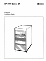
1
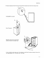
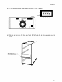
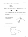
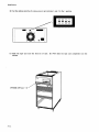
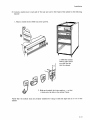
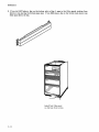
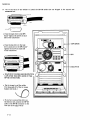
1-1 P
...
~nnn
~AriA~
...... ...................
....... ~7
... .
Customer
Installation Guide
~
HP 3000 Series 37
Customer Installation Guide
Pi) ~:~K':~~
8010 Foothills Blvd., Roseville, CA 95678
Part No, 30457-90001
E1184
Prin ted in U. s. A. 1 1/84
NOTICE
The information contained in this document is subject to change without notice.
1
HEWLETT-PACKARD MAKES NO WARRANTY OF ANY KIND WITH REGARD TO THIS
MATERIAL, INCLUDING, BUT NOT LIMITED TO, THE IMPLIED WARRANTIES OF
MERCHANTABILITY AND FITNESS FOR A PARTICULAR PURPOSE. Hewlett-Packard shall not
be liable for errors contained herein or for incidental or consequential damages in connection with the
furnishing, performance or use of this material.
Hewlett-Packard assumes no responsibility for the use or reliability of its software on equipment that
is not furnished by Hewlett-Packard.
This document contains proprietary information which is protected by copyright. All rights are
reserved. No part of this document may be photocopied, reproduced or translated to another language
without the prior written consent of Hewlett-Packard Company.
Copyright © 1984 by HEWLETT -PACKARD CO:\r1PANY
I
PRINTING HISTORY
New editions are complete revisions of the manual. Update packages, which are issued between editions,
contain additional and replacement pages to be merged into the manual by the customer. The dates on
the title page change only when a new edition or a new update is published. No information is
incorporated into a reprinting unless it appears as a prior update; the edition does not change when an
u pda te is incorporated.
The software code printed alongside the date indicates the version level of the software product at the
time the manual or update was issued. Many product updates and fixes do not require manual changes
and, conversely, manual corrections may be done without accompanying product changes. Therefore, do
not expect a one to one correspondence between product updates and manual updates.
First Edition. . . . ..
. . . . . . . Nov 1984. . . . . . . . . . . . . . . . . . . .
Nov 84
111
LIST OF EFFECTIVE PAGES
The List of Effective Pages gives the date of the most recent version of each page in the manual. To
verify that your manual contains the most current information, check the dates printed at the bottom of
each page with those listed below. The date on the bottom of each page reflects the edition or subsequent
update in which that page was printed.
Nov 84
iv
Eff ecti ve Pages
Date
all . . . . . . .
. Nov 1984
Nov 84
PREFACE
This manual contains the information that you need to install your computer hardware. Once you have
correctly installed your computer, use the Series 37 Software Installation Procedures to install your
software.
NOV 84
v
Table of Contents
Section 1
GENERAL INFORMATION
1.0 Introduction . . . .
1. 1 System Description .
1-1
1-2
Section 2
PREPARING FOR YOUR SYSTEM
2.0 Introduction . . . . . . . . . .
2-1
2-1
2-2
2. I Prior to Installation: A Checklist.
2.2 Principal Operator . . . . . . . .
HP People Who Can Help. . . . . .
Third Party People Who Can Help .
2. 3 Space and En vironmen t Planning.
Environmental Considerations
Temperature and Humidity . . .
2.4 Electrical Requirements . . . . .
2.5 Sources of Electrical Interference
Lightning . . . . . . .
Radiated Interference . . . . .
2.6 Contaminants . . . . . . . .
2. 7 Providing Other Necessities.
~edia Storage. . . . . . . . .
Protection of Valuable Records.
Telephone ..
2.8 Unpacking . . . . . . . . . .
2-2
2-2
2-3
2-4
2-4
2-5
2-5
2-5
2-6
2-6
2-6
2-6
2-7
2-7
2-7
Section 3
INSTALLATION
3. 0 Introduction . . . . .
3. I Installation Procedure
3.2 Troubleshooting . . . .
3.3 Software Installation.
· 3-1
· 3-2
3-24
3-24
Appendix A
ELECTRICAL SPECIFICATIONS
Introduction . . . . .
Power Specifications.
Line Voltage . .
Line Frequency.
Safety Ground .
Current . . . . .
Separate Circuit Breakers.
Power Line Transients
Direct Connections
Approvals . . . . . . . .
VI
·
·
·
·
·
A-I
A-I
A-I
A-I
A-2
·
·
·
·
·
A-3
A-3
A-4
A-5
A-6
Table of Contents
Appendix B
CONSOLE CONFIGURATION
Introduction. . . . . . . .
Selecting Operating Modes.
Configuration .
HP 2392 . . . . . . . .
HP 262X . . . . . . . .
HP 1 SO -- the Touchscreen
·
. .
·
·
·
..
vii
B-1
B-1
B-2
B-2
B-2
B-3
1~____________~Ioo
GENERAL INFORMATION
1.0 INTRODUCTION
This manual introduces you to your HP 3000 Series 37 computer system and explains how to prepare for
and install your computer. The customer-instaUable system can include the following:
*HP
*HP
*HP
*HP
HP
HP
HP
HP
HP
30463A System Cabinet
32449A System Processor Unit
7945A Disc Drive (55 Mb)
9144A Cartridge Tape Unit (67 Mb)
239 2A Terminal
2623A Terminal
2624B Terminal
2625A Terminal
2628A Terminal
HP 2601/2 Printer (20-25 CPS)
HP 2686 Printer (8 PPM)
HP 2932/3/4A Printer (200/100/200 CPS)
HP 7470A Plotter (2-pen)
HP 747 5A Plotter (6 -pen)
HP 150 Personal Office Computer
*These devices, plus one terminal designated as the system console, compose the minimum system.
This manual can be used by the first-time computer user. The only tools required are a flat-blade
screwdriver and an open- end 3/8" wrench.
Section 2 provides the information that you need to verify that your office environment will support your
computer system. Most offices require no modification. However, read Section 2 so that you are aware
of any potential problems and can remedy them prior to installation.
Section 3 guides you through the installation procedure.
Appendix A contairls the technical information that your electrician may need.
Appendix B contains the procedure for configuring a terminal as the console.
The list of Sales & Support Offices is in alphabetical order by country. If you decide to add a device that
is not included in this manual, consult with your Hewlett-Packard representative.
Follow the guidelines in this manual to help ensure that your system operates properly. For continued
long-term service, we recommend an HP service contract.
1-1
General Information
1.1 SYSTEM DESCRIPTION
Your computer system is made up of a group of devices that communicate with each other in order to
perform tasks for you. When you install your system, you provide the communication links when you
plug in the HP-IB and RS-232 cables. See Figure 1-1.
The heart of your system is the System Processor Unit (SPU). The standard SPU contains four boards:
.r-
1. Central Processor Unit (CPU - located in slot 5) - capable of processing 200,000 machine instructions
per second (0.2 MIPS). The CPU also performs a comprehensive, built-in system self-test, verifies
';
system problems, and performs routine testing on system hardware. The CPU is designed to be software
~. '. )·';rl~ compatible with all HP 3000 computers, enabling you to expand your system as your needs grow.
lJ· 1! (
.1 ;-1'< f/
2. Peripheral Interface Controller (PIC - located in slot 4) - a high -speed interface that utilizes the HP
'.
Interface Bus (HP-IB). The PIC communicates with the tape, disc units, and system printers.
3. Memory (located in slot 2) - stores up to 512,000 bytes (512 kb) of information on a single board.
This board can be replaced by a 2,048,000 byte (2048 kb) board.
4. Advanced Terminal Processor for the Series 37 (ATP37 - located in slot 1) - RS-232 serial interface.
The ATP37 provides one port to communicate with the modem and six ports to communicate with
terminals, plotters, and printers.
Slot 3 is an optional slot provided for either a second ATP37 board (that gives you the capability to
connect seven additional terminals and/or printers and/or plotters) or a second 512 kb memory board
(that increases your storage capacity to 1024 kb).
The Tape Unit allows you to store and retrieve data.
The Disc Drive is a "random access" memory device that is capable of storing information. The system
program and your applications are stored on the disc.
The console is a terminal that is plugged into Port O. It is primarily used to provide system control
(system start, backup, and stop) in addition to performing the functions of a terminal.
A terminal or personal computer allows you to communicate with the system, enabling you to perform a
variety of tasks efficiently.
A plotter provides a variety of graphics capabilities.
A printer provides high -quality printing at a speed that meets the needs of a small business system.
All of your system's devices perform built-in self -tests. The successful completion of the self -tests
indicates that your system hardware is performing correctly even before you begin your work.
1-2
General Inf orma tion
Tape Unit
Back View
HP-IB
Keyswitch
SPU
RS-232
RS-232
RS-232
RS-232
Terminal
Figure 1-1. The HP 3000 Series 37 Computer System
1- 3
(~' .~.
,f ....1
1~____________~IOO
PREPARING FOR YOUR SYSTEM
2.0 INTRODUCTION
This section provides the information that you need to prepare for the instaliation of your computer
system. This information will help you decide where to put your system, what to have ready when your
system arrives, and how to receive your system.
Most facilities require no alteration. However, we recommend that you read this section thoroughly in
order to verify that your environment supports your computer.
This section includes:
* "Prior to Installation: A Checklist
* "Principal Operator" - describes the role of a principal operator and the assistance that person has.
* "Space and Environment Planning" - provides the system dimensions, environmental and electrical
II
requirements, and defines possible sources of interference or contamination.
* "Providing Other
Necessities" - describes additional items necessary to computer operation, such as
media storage, computer supplies, and telephone access.
Although you are responsible for providing a suitable environment for your computer system, no extensive
preparation should be required. If your office is unusual, Hewlett-Packard or your system supplier may
recommend that you purchase HP's Site Planning Service.
2.1 PRIOR TO INSTALLATION: A CHECKLIST
The items in this list are expanded upon in the text that follows the list.
1. Select a Principal Operator to be responsible for the preparation, installation and operation of your
computer system. System operator training is REQUIRED prior to installing the system.
2. Select a location for your system. Plan the physical arrangement of your system and furniture.
3. Call your building maintenance people to verify that your electrical wiring is connected to approved
ground and that it provides adequate current to supply power to ALL of your electrical equipment.
4. Check the average temperature and humidity of your environment.
s.
Install climate conditioning
Order consumable supplies, including printer paper and ribbon, and plotter paper and pens (available
from Hewlett-Packard). Set up a storage area.
2-1
Preparing for Your System
6. When you receive your system, inspect the cartons for any damage. If there is evidence of damage,
request that the carrier's representative be present when that carton is unpacked.
2.2 PRINCIPAL OPERATOR
Select someone to be the Principal Operator. This person is responsible for monitoring the installation,
operation, and maintenance of your system. Initially, the Principal Operator will order computer supplies,
and schedule training for system users. The Principal Operator should become familiar with the system
and be ready to start its operation when the system is installed. System operator training is REQUIRED
before installing the system.
HP People Who Can Help
Below is a list of Hewlett-Packard service personnel. Each member of the HP team is well trained and
dedicated to helping you make maximum use of your computer system.
Sales Representative - your primary contact. Your sales representative coordinates HP resources to ensure
on -time delivery of your system. Call your sales representative to arrange staff training or to acquire
additional system devices-;f
Customer Engineer (CE) - the expert in computer and peripheral equipment service.
The CE has the
tools, parts, and skills to maintain your computer system. If you purchase an HP Maintenance Agreement,
the CE will provide hardware maintenance, repair, and problem diagnosis.
Systems Engineer (SE) - the technical specialist in subsystems and programming languages.
Your SE
offers training and technical consulting on the programming language, utility programs, data base
management, and system performance. The SE will provide software consulting and software problem
diagnosis. Your sales person can describe the various software support services available to you.
Third Party People Who Can Help
Original Equipment Manufacturer JOEM) or System House -- If you have purchased an HP computer
system and/or applications softwate from someone other than HP, that party will provide consultation
services on system operation and/ applications software (programs). In this situation, a maintenance
agreement for hardware support is1available from Hewlett-Packard.
2-2
Preparing for Your System
2.3 SPACE AND ENVIRONMENT PLANNING
The location that you select for your system should satisfy both immediate and future needs. Select a
location that enables you to add more equipment as your needs expand and ensures that you have
sufficient room to operate, ventilate, and service your equipment. If you expand beyond a minimum
system, the expansion requires CE site preparation and installation. If you are definitely planning to
expand, it may be less expensive to have the CE do the site preparation now.
Remember that the length of the cables may restrict future moves. Plan to keep cables away from traffic
paths. Hewlett- Packard supports the RS-232 cables up to 15 meters (50 feet) in length.
The cabinet that houses the SPU, disc drive, and tape unit is designed to sit on the floor. It is 720 mm (33
inches) high, 375 mm (15 inches) wide, and 711 mm (32 1/2 inches) deep. You should NOT plan to set
anything on top of your cabinet. Provide a minimum of 152 mm (6 inches) of free space behind the
cabinet for ventilation during operation. For servicing, provide at least 795 mm (36 inches) of open space
in front of and behind the cabinet, or ensure that the cables are long enough to move the cabinet into an
open area.
I CAUTION I
To move the cabinet, raise the legs by turning them counterciockwise.
Because the cabinet is front-heavy, it can tip when you are moving it.
Push it from the front. Keep the legs down when you are not moving the
cabinet.
I CAUTION I
Do not move the cabinet while the disc drive is on. Disc damage may
result.
The remaining devices in your system are designed to sit on desk or table tops. The amount of space that
you need is determined by the number of terminals, printers, and plotters that you have.
2-3
Preparing for Your System
Environmental Considerations
Temperature and Humidity
Higher operating temperatures increase the failure rate of electronic circuitry. High humidity can cause
device malfunctions or improper feeding of printer or plotter paper, while low humidity aggravates
problems with static electricity. See Figure 2-1.
Figure 2-1. Temperature and Humidity Requirements
Your system has a high resistance to static electricity. However, if you have an abnormally high level of
static electricity (25 kV or more - at this level, people will probably be "sparking" on contact), you may
want to use a humidifier or place a grounded floor mat in front of your system. Excessive amounts of
static electricity can cause system failures.
Your computer is air-cooled. Fans circulate air through the system and discharge warmer air into the
room. Maintain a minimum of 152 mm (6 inches) of free space in front of and behind the cabinet to
allow warm air to dissipate properly. Place terminals on a hard surface, NOT on a typewriter pad, so that
air can circulate below the terminal.
If you intend to use your system on weekends, be aware that the temperature and humidity in your
building may vary from the normal workday conditions. In extreme environments, auxiliary air
conditioning or heating might be required to prevent damage to the equipment. If you feel that it's
necessary, use a thermometer and humidity gauge to monitor your site. ~
l'
2-4
Preparing for Your System
2.4 ELECTRICAL REQUIREMENTS
Your computer system has specific electrical requirements.
maintenance people to verify that:
You need to check with your building
• your electrical circuitry is grounded according to code
• your wall outlets provide safety ground
• the equipment to be put on each circuit breaker draws no more than 80% of the capacity of
that circuit breaker
• your circuitry provides an input voltage range of: 100-120 volts +/ - 10% (order standard)
OR 200- 240 volts +/ - 10% (order option 15)
If you do not meet the above requirements, you need the assistance of an electrician. The information
that your electrician needs is in Appendix A. If you add a device to your system that is not covered in
this manual, consult with your HP representative about additional electrical requirements.
2.5 SOURCES OF ELECTRICAL INTERFERENCE
Heavy equipment (e. g. vacuum cleaners, floor buffers, and copiers) must not be plugged into the same
circuit as the computer system while the system is on. Voltage surges created by heavy equipment can
ca use system errors.
Appliances that draw a lot of current (for example, heaters, hot plates, and coffee makers) should also be
plugged into a separate circuit.
Lightning
In some geographical areas, it is advisable to install lightning protection for personnel and the computer.
The National Electrical Code, Article 280, describes the installation of lightning arrestors on power and
communication lines in the United States.
2-5
Preparing for Your
Syste~
Radiated Interference
Radiated interference causes a variety of computer problems, most commonly disc read/write errors.
Common sources of radiation are nearby:
• airport communications and radar
• two-way radio transmitters
• television transmitters
• radio transmitters
• microwave transmitters
Hand-held transceivers (e. g. "walkie-talkies") produce the same effect as radio stations when used near
computer equipment and should be prohibited from the areas in which computer equipment is operated.
Although your system is designed to withstand high levels of radiated interference, you may want to
contact your HP representative if you suspect a potential problem.
2.6 CONT AMINANTS
Fundamental safety precautions should be taken to minimize potential sources of damage. Do not install
the system where there is a fire hazard from liquids, flammable gasses, or excessive dust.
Foreign particles may scratch the coating on the tape drive head, causing premature disc wear and/or data
errors. The most common contaminants are dust, smoke, ashes, eraser crumbs, salty air, and food. Solvent
vapors, such as those from liquid spirit duplicating equipment, wet process copiers, and volatile liquids, can
soften disc coatings over a period of time. To prevent excessive wear, avoid getting these contaminants on
your system.
2.7 PROVIDING OTHER NECESSITIES
Your sales representative can help you order your computer supplies. Necessary items include printer
ribbon and paper and plotter paper and pens. These items are available from Hewlett-Packard.
Media Storage
We recommend that you provide a storage cabinet for tapes. Magnetic media have the same requirements
as the computer for avoiding extremes of temperature and humidity. To maintain data integrity, do not
place recorded media near magnetic fields (around motors, alternators, transformers, or disc drives).
2-6
Preparing for Your System
Protection of Valuable Records
Your investment in equipment and data deserves protection. Protect your business records, magnetic
media, and other information that is expensive or difficult to duplicate. Backup records should be
maintained. Copies of vital data should be stored away from the computer area in fireproof storage.~
Because you are making a significant investment, you may want to look into obtaining electronic data
processing insurance.
"*
Telephone
It is a good idea to place a telephone with a long cord near your system, so that you may easily consult
with a service representative.
Install an additional telephone to be used with a modem if the far-end of the communication link is to be
manually answered. FCC regulations require that you notify the telephone company before you install a
modem.
2.8 UNPACKING
If any cartons that your system shipped in appear to be damaged, request that the carrier's representative
witness the unpacking. If the system has been damaged, contact your Sales Representative for assistance.
2-7
~IN_S_T_A_LL_A_T_IO_N_-______________~Ir!i'i',
3.0 INTRODUCTION
This chapter contains the instructions for installing your system. READ this entire chapter before you
begin the installation.
NOTE
The installation procedure will refer you to other manuals. Each manual is
shipped in the carton with its associated device.
Install the devices in the order specified in this chapter.
NOTE
If there are discrepancies between the items you ordered and the items you
received, call your Sales Representative. Do NOT perform the installation
until the discrepancies have been corrected.
NOTE
If you order and receive an HP 3000 I/O Extender (HP 30458A), you
MUST have site preparation and installation performed by HP personnel.
SA VE the documentation and the packing lists.
It is a good idea to monitor your installation progress by treating the following installation procedure as a
check list. This manual is yours-- feel free to use the open spaces for your notes.
3-1
Installation
3.1 INST ALLA TION PROCEDURE
1. Unpack the system cabinet (HP 30463A). The carton will contain the following:
• Cabinet
• Power Cord *
• Filler Panels (in the Cabinet Installation Kit)
• Module Locks (in the Cabinet Installation Kit)
*A11 non -120V systems will be shipped with additional power cords.
3-2
Installa ti on
2. Remove the following from the Miscellaneous Parts Kit (shipped in the carton with the manuals):
• SPU Key - keep it in a designated location
• Dust Covers· - used in Step 1 3
• Cable Clamps - used in Step 14
[!]
"liIIililill"""III"I111""I111"""""IIIiIIIIi"""""II'IIII""
$
iii
Tie Wraps - used in Steps 13 and 16
Leave the rest of the kit intact and store it in a designated location so that it will be available if a service
call is ever necessary.
Place the filler panels, module locks, SPU key, dust covers, cable clamps, and tie wraps in an easily
accessible location. You will use them in the installation procedure.
3-3
Installa tion
3. Place the cabinet near the planned location. To make the cabinet stable, manually lower the four legs
to the floor by turning them clockwise.
FRONT
3-4
Installation
4. Manually unsnap and remove (a) the back panel, (b) the top panel, and (c) the front locking frame.
A.
Pull SHARPLY on handle.
.~
Pop off top panel.
c.
Manually unscrew the two top locking
screws and remove the locking frame.
-FRONT
Look at the label on the bottom rear of the cabinet to verify that the electrical rating is the one that
you ordered (either 100 - 120 volts or 200 - 240 voltS').
3-5
Installation
5. Unpack the HP7945A disc drive. The carton will contain the following:
•
•
•
•
Disc Drive
Manual(s)
Power Cord
HP-IB Cable
(a) Look at the back of the disc drive to verify that the voltage selector switch is set for the input
voltage provided by your site.
If you need to change the voltage selector, slide it towards the visible voltage rating with a
screwdriver until the correct voltage rating is displayed.
(b) CAREFULLY place the disc on its side and remove the two front mounting feet from the bottom
of the disc drive by:
• lifting the back of the mounting foot
with the screwdriver (1),
• sliding the mounting foot back (2), and
• lifting the mounting foot out (3).
Note: Do not be concerned if a mounting foot breaks - you do not need them.
(c) Peel off the two mounting feet on the bottom rear of the disc drive.
:
j.
-~iJ
Ii i
U I
3-6
Installation
(d) Set the address switches by using a pen to slide switch 1 to the 1 position.
II
-
(e) Slide the disc drive onto the third set of rails. Do NOT slide the disc drive completely into the
cabinet.
POWER OFF (out - 0)
3-7
Installa tion
(f) Attach a module lock to each side of the disc drive and to the frame in the following manner:
1. Place a module lock in both top corner grooves.
2. Hold the module
locks in place while
you slide the disc
into the cabinet.
3. Slide each module lock into position -- so that
it clicks into the hole in the cabinet frame.
Verify that the module locks are properly installed by trying to slide the disc drive in or out of the
cabinet.
NOTE
If you have a second disc drive, set the address switches on that disc (as
shown below), slide the disc into the space below the first disc, and attach
the module locks.
o
X
3-8
4
2
Installation
6. Unpack the SPU.
(a) Look at the warranty label on the back of the SPU to verify that you received the option that you
ordered (either Standard or Option 15).
(b) If necessary, use the SPU key to turn the keyswitch to the OFF (0) position. Do NOT leave the key
in the keyswitch.
-
AC
I
DC
BATTERY
i/o
REMOTE
'r:J)
o
3
(c) Slide the SPU onto the second set of rails. Do NOT slide the SPU completely into the cabinet.
3-9
Installa tion
(d) Attach a module lock to each side of the SPU and to the frame of the cabinet in the following
manner:
1. Place a module lock in both top corner grooves.
•& \)(.... II
I
2. Hold the module
locks in place while
you slide the disc
into the cabinet.
I
I
I
I
I
3. Slide each module lock into position -- so that
it clicks into the hole in the cabinet frame.
Verify that the module locks are properly installed by trying to slide the SPU into or out of the
cabinet.
3-10
Installa tion
7. Unpack the HP9144A tape unit. The carton will contain the following:
• Tape Unit
• ManuaI(s)
• Power Cord
(a) Look at the back of the tape unit to verify that the voltage selector switch is set for the input
voltage provided by your site.
H~
If you need to change the voltage selector, slide it towards the visible voltage rating with a
screwdriver until the correct voltage rating is displayed.
(b) CAREFULLY place the tape unit on its side and remove the two front mounting feet from the
bottom of the tape by:
• carefully using a screwdriver, lift
the back of the mounting foot out of
the hole in the tape unit (1),
• sliding the mounting foot back (2), and
• lifting the mounting foot out (3).
Note: Do not be concerned if a mounting foot breaks - you do not need them.
(c) Peel off the two feet on the bottom rear of the tape unit.
• ..
•
.
.
3-11
Installation
(d) Set the address switches by using a pen to set switches 1 and 2 to the 1 position.
I
I
-.
a
o
X
4
2
(e) Slide the tape unit onto the first set of rails. Do NOT slide the tape unit completely into the
cabinet.
POWER OFF (out - 0)
3-12
Installation
(f) Attach a module lock to each side of the tape unit and to the frame of the cabinet in the following
manner:
1. Place a module lock in both top corner grooves ..
,....
\)
2. Hold the module
locks in place while
you slide the disc
in to the cabinet.
3. Slide each module lock into position -- so that
it clicks into the hole in the cabinet frame.
Verify that the module locks are properly installed by trying to slide the tape unit in or out of the
cabinet.
3-13
Installa tion
8. If you did NOT place a disc on the bottom rails in Step 5, snap in the filler panels, working from
bottom to top, leaving the bottom space open. If you DID place a disc on the bottom rails, snap in one
filler panel below the disc.
Install first filler panel
in 2nd hole from bottom.
3-14
Installa tion
9. Unpack the terminal that is to be used as the system console. The carton will contain the following:
•
•
•
•
Terminal and Keyboard
Manual(s)
Power Cord
RS-232 Cable
Place the console in its planned location. Turn the power OFF.
NOTE
Items 10 through 12 apply to optional equipment. If you do not have one
of the following items, simply proceed to the next step.
10. Unpack the printer. The carton will contain the following:
•
•
•
•
Printer
Manual(s)
Power Cord
RS-232 Cable
Place the printer in its planned location. Turn the power OFF.
11. Unpack the plotter. The carton will contain the following:
•
•
•
•
Plotter
Manual(s)
Power Cord
RS-232 Cable
Place the plotter in its planned location. Turn the power OFF.
12. Unpack the remaining terminals. Each carton will contain the following:
•
•
•
•
Terminal
Manual(s)
Power Cord
RS-232 Cable
Place the terminals in their planned locations. Turn the power OFF on each terminal.
3-15
Installa tion
13. Go to the back of the cabinet to install the HP-IB cables that are shipped in the manual and
accessories box:
• from the tape drive to the SPU
(hand -tigh ten the screws on each
side of the connectors)
--1
11 ...
• from the disc drive to the tape
drive connector on the SPU (handtighten the screws on each side
of the connectors)
.......+r-I--'TAPE DRIVE
.....~I--SPU
.....++-+--DISC DRIVE
• SNAP DUST COVERS/ESD PROTECTIVE
CAPS OVER THE OPEN ENDS OF THE
UP-IB CONNECTORS.
• Use tie wraps to coil the cables.
(Cut long ends off of the tie wraps.
Scissors will work.)
• If you have a second disc drive on
the bottom rails, connect the HP - IB
cable to the HP-IB connector on the
first disc drive (piggy-back).
3-16
Installation
1 4. Install the RS - 2 3 2 ca bles:*
• for a modem, or any peripheral that
connects to the SPU with a 25-pin
connector (2601/2 printers**)
o
1
2
•
f rom the console to port 0
• from the terminals and plotters***
to ports 1-4
5
4
3
• from the printer to port 5 (for
additional printers, use ports 4-1)**
• Attach the adhesive clamp(s) on top
of the second/third rails on the right
(toward the rear of the cabinet).
Route the RS-232 cables through
them. Close the clamps to hold the
cables in place.
*Refer to the preparation/installation/set-up sections of your peripheral
**To connect the 2601/2 printer(s), refer to the direct connections section of Appendix A.
***Connect either (1) directly to the SPU, or (2) to a terminal and then connect the terminal to the SPU.
3-17
Installation
15. Fill out this form and keep it with the Miscellaneous Parts Kit so that it will be available if a service
call is necessary.
Peripheral Interface Channel (Slot 4)
Device
Address
Product
Number
Description
1
HP7945A
55 Mbyte Disc Drive
2*
3
HP9144A
Cartridge Tape Unit
LDEV II
DRTII
1
33
2
34
7
35
*If you have a second disc drive, the product number and description will be the same as that for device 1.
ATP37 (Standard in Slot 1; Add-On in Slot 3)
Port/Unit II
Product II
Description
LDEVII
DRTII
Standard:
0
console
20
8
1
21
8
2
22
8
3
23
8
4
24
8
5
25
8
7
27
8
Add-On
(Option 001):
3-18
I
0
30
24
1
31
24
2
32
24
3
33
24
4
34
24
5
35
24
7
37
24
Installa tion
**This page deliberately blank. **
Installa tion
16. Verify that all power switches are OFF. Install the AC power cords (use the power cords that fit the
power strip):
NOTE
Do NOT plug any power cords coming from peripherals outside the cabinet
into the AC power strip at the bottom of the cabinet.
I
• from the tape drive to the power
strip
TAPE DRIVE--+-+H'"
• from the SPU to the power strip
DISC DRIVE --+-++41-
• from the disc drive to the power
strip
• Route cables and cords through the
two cable supports.
POWER STR I P
-t-Tf---f----1-
• Use tie wraps to neatly coil the
power cables. Cut off the long
ends of the tie wraps.
REVIEW STEPS 13, 14, and 16 TO VERIFY THAT ALL CONNECTIONS HAVE BEEN MADE AND
THA T ALL CONNECTORS ARE SECURE.
3-20
Installation
17. Verify that you have connected all peripherals. Securely replace the (a) front frame, (b) top panel,
and (c) back panel of the system cabinet. Move the system cabinet into the planned location.
CAUTION
To move the cabinet, you need to turn the legs counter-clockwise with a
3/8" wrench. Because it is now front-heavy, it can tip. Do NOT sit on the
cabinet and do NOT push it from the rear or sides. Push it from the front.
Keep the legs down when you are not moving the cabinet.
18. Plug the AC power cords from all peripheral devices and the system cabinet power strip into
grounded wall outlets.
19. Turn on the disc drive and tape unit. Each unit will perform a self -test. When the disc drive(s)
successfully complete self -test, the green indicator on the front panel will light. If the tape unit fails
self -test, the indicator will r.ead FAULT. If it passed, there is no indicator.
I CAUTION I
Dc NOT mcve the system cabinet while the disc drive is turned on. Disc
damage may result.
3-21
Installa tion
20. Prepare the peripheral devices in the following order:
NOTE
Do NOT turn on the SPU until Step 21.
• Using the appropriate terminal manual as a guide, connect the keyboard to the back of the
terminal that will be the console. Configure the console, setting the baud rate to 9600
(preferred), the parity to 0, the data bits to 7, and the stop bits to 1. ENQ/ ACK must be
enabled (YES). Appendix B describes the correct procedure for the individual terminals.
HP2392A Display Terminal User's Manual -- Section I
HP2623A User Manual -- Section 2
HP2624B User Manual -- Section 2
HP2625A/2628A User's Manual -- Section 2
• Using the printer manual(s) as a guide, install the paper and ribbon in the printer(s).
HP260lA Installation & Reference Manual -- Section 3
HP2602A Daisywheel Printer Owner's Manual -- Preface and Section 1
HP2930 Series Printers Owner's Manual -- Section 1 (through Loading Paper)
HP2686 Operator's Manual -- Section 2
HP 2687 Opera tor's Manual - - Section 3
• Using the plotter manual(s) as a guide, install the paper and pens in the plotter(s).
HP7470A Interfacing and Programming Manual -- Setting Up Your RS-232-C Plotter
HP7475A Interfacing and Programming Manual -- Setting Up Your RS-232-C Plotter
• Using the appropriate terminal manual(s), connect the keyboard(s) to the terminal(s).
HP2392A Display Terminal User's Manual -- Section 1
HP2623A User Manual -- Section 2
HP2624B User Manual -- Section 2
HP2625A/2628A User's Manual -- Section 2
• Turn on each peripheral device. Each device will perform a self -test.
3-22
Installation
21. Use the key to turn the SPU keyswitch to LOCAL (2).
I~·------II
Ii •
:~--*'--+--
The self -test display will flash a 0, 1, 5, B, C, and A during the self -test process. When self -test
passes, the final display will be blank. The console will display:
Power on Self Test
Memory Test passed
Number of banks = n
Slot 1 channel 1 - Terminal Interface Controller
optional (TIC will be Slot 3 Channel 3)
Slot 4 Channel 4 - Peripheral Interface Channel
2 - LOCAL (from Normal)
H for Help ->
Respond to this message by typing TEST or TE.
2-LOCAL (from Normal)
Test ->
Respond to this message by typing IOMAP or I to get this display:
System I/O Configuration
Number of bank = n
Load:
Channel 4 Device 3
Start/Dump: Channel 4 Device 1
Slot 1 Channel 1 10
=4
- Terminal Interface Controller
Slot 3 Channel 3 10 = n Note: the optional slot -- may not be displayed.
Slot 4 Channel 4 10 = 2 - Peripheral Interface Channel
Device 1 1D = 0220 - 7945 Disc Drive
Device 3 10 = 0260 - 9144 Cartridge Tape Unit
2-LOCAL (from Normal)
Test ->
Respond to this message by typing EXIT or E to exit.
If you do NOT see this configuration on your console, verify that you have set the HP-IB address switches
and connected the cables correctly. Refer to the following section on troubleshooting.
3-23
Installation
3.2 TROUBLESHOOTING
If you have any problems, there are a few simple checks that you can do. Refer to Table 3-1.
Table 3-1. PROBLEMS/SOLUTIONS
PROBLEM
1. SPU self -test display is NOT blank (may be
in a repetitive sequence) - console may
indicate the error, followed by the
H for HELP> prompt.
2. No console display.
SOLUTION
Check the tape and disc: cable connections
address switches
power-on indicators
Check that: the console has power (plug,switch)
the console cable is connected
the console is in remote mode
the console is configured properly
the brightness control (if present)
is adjusted
3.3 SOFTWARE INST ALLA TION
Once you have installed your computer, you are ready to follow the Series 37 Software Installation
Procedures to install your software.
3-24
'----EL_E_C_T_R_IC_A_L_S_P_E_C_IF_IC_A_T_IO_N_-S_ _ _
---'II~I!II.I,
INTRODUCTION
This appendix contains the information that your electrician needs to verify that your office meets the
electrical requirements of your HP 3000 Series 37. If you meet the requirements outlined in Section 2,
you do not need to have an electrician use this appendix.
POWER SPECIFICATIONS
The power specifications for the HP 3000 Series 37 are:
Line Voltage
The Series 37 requires a single phase power system with nominal voltage of:
100 - 120 VAC +/-10% (90 - 132 VAC) or
200 - 240 VAC +/-10% (180 - 264 VAC)
Power voltages outside the specified operating range can cause intermittent system errors or shutdown.
Low voltage is the most common power problem, and is usually caused by inadequate wiring.
Line Frequency
The required line frequency is 48 Hz to 66 Hz. Line frequency usually depends on the local electric
company. Power is rarely generated by a motor inside your building. Incorrect line frequency can cause
intermittent system errors or display jitter.
A-I
Appendix A
Safety Ground
Safety ground is required as protection for operating personnel and equipment. Every wall outlet used by
the system must have a safety ground.
The green -wire ground is connected to the metal frame of each system device to protect an operator
against equipment malfunction, and to make the equipment resistant to a catastrophic event such as a
lightning strike. Be sure that the green -wire ground is connected from the wall outlet to the distribution
sub-panel where the circuit breaker is installed.
Figure A-I illustrates the three-conductor grounded power cords that are offered with the HP 3000.
U.S.A., Canada, Japan, Mexico,
Philippines, Taiwan
Option 903 (standard)
HP Part Number: 8120-2371
Length: 2.29m (7.5 ft)
Rating: 125V, 13a, single phase
NEMA5-15P
Great Britain, Cyprus, Nigeria,
Rhodesia, Singapore
Option 900
HP Part Number: 8120-1351
Length: 2.29m (7.5 ft)
Rating: 250V, 10a, single phase
BS 1363A
Australia, New Zealand
Option 901
HP Part Number: 8120-1369
Length: 2m (6.5 ft)
Rating: 250V, 6a, single phase
AS C112
U.S.A., Canada, Japan, Mexico,
Philippines, Taiwan
Option 904
HP Part Number: 8120-0698
Length: 2.29m (7.5 ft)
Rating: 250V, 6a, single phase
NEMA6-15P
,
Switzerland
Option 906
HP Part Number: 8120-2104
Length: 2m (6.5 ft)
Rating: 250V, 6a, single phase
SEV 1011
Denmark
Option 912
HP Part Number: 8120-2956
Length: 2m (6.5 ft)
Rating: 250V, 6a, single phase
DHCR 107
Belgium, Italy, France, Spain,
Greece, Austria, Finland,
Germany, Netherlands, Norway,
Sweden, Saudi Arabia,
United Arab Republic
Option 902
HP Part Number: 8120-1689
Length: 2m (6.5 ft)
Rating: 250V, 6a, single phase
CEE7-VII
Figure A-I. Power Cords (U.S. and International)
A-2
Appendix A
Current
The cabinet AC power strip is rated at IS-amperes (U.S. and Canada). Table A-I shows the amount of
current drawn by each device.
Table A-t. TYPICAL CURRENT DRAWN BY EACH DEVICE
Device
(Circle) Amperage Drawn at:
100V 120V 220V 240V
HP 150
1. 1
1.0
0.6
0.5
HP 2392
0.5
0.4
0.2
0.2
HP 2601/2
1.0
0.9
0.5
0.5
HP 2623
1.2
1.0
0.6
0.5
HP 2624/5
1.0
0.8
0.5
0..4
HP 2628
1.0
0.8
0.5
0.4
HP 2932
3.0
2.5
1.4
1.3
HP 2933/4
3.0
2.5
1.4
1.3
HP 7475
0.4
0.3
0.2
O. 1
HP 7945
1.4
1.2
0.7
O. 7
HP 9144
0.8
O. 7
0.4
0.3
HP 32449A
2.2
2.0
1.7
1.1
HP 35141A
0.1
.01
.05
.05
(Multiply by)
Number of
Machines
TOTAL:
(Equals) Total
Amperage
Drawn
TOTAL:
Separate Circuit Breakers
Available current cannot exceed 80% of the circuit breaker rating (eg. 12 amperes for a IS-ampere
circuit breaker).
If expansion beyond a minimum system is planned (adding a larger disc unit, tape unit, or HP-IB printers),
a separate circuit breaker for the system is suggested, but not required. Separate circuit breakers ensure
sufficient power to avoid data errors and to isolate the system from any faulty equipment. Typical
A-3
Appendix A
circuit breakers in the U. S. are rated at 15 or 20 amperes. The current load in each circuit should allow
a margin for startup and surge currents caused by the system.
Power Line Transients
Heavy electrical loads from nearby machinery or equipment, like elevators or electric welders, can cause
intermittent system errors even if that equipment is on a different circuit breaker. For those conditions,
you must provide a separate, completely independent circuit with isolated ground and a circuit breaker
coming directly from the main building power source. In cases of severe electrical noise, it may be
necessary to install an isolation or power line conditioning transformer.
Where multiple circuits are needed to provide the required total amperage protection, consult local
electrical codes to determine the appropriate circuit breaker sizes and load distribution (maximum breaker
for common receptacles in the United States is 20 Amperes; in Canada, 15 Amperes).
A-4
Appendix A
DIRECT CONNECTIONS
The Advanced Terminal Processor for the Series 37 (ATP37) (HP Product 30460A), is capable of
communicating with supported workstations, printers, and plotters via an RS-232-C data link, using a
direct hardwired connection.
The EIA RS-232-C standard defines the mechanical/electrical
characteristics for devices which can connect to the ATP37 interface. See Figure A - 2. Supported options
are reported in the Configuration Guide that is available from your Sales Representative.
~SPU
Printer
Figure A-2. 2601/2 Printer Cable to 3000l52A Cable
DIRECT CONNECT PORTS
2392
40242X
SERIES 37
(RFI FILTERED)
2623
OR
2628
13242X
SERIES 37
MODEM PORTS
2392
2623
OR
2628
40242M
SERIES 37
OR
MODEM
13242 MIN
SERIES 37
OR
MODEM
EUROPEAN/US
MODEM CABLE
L....-M_O_D_E_M.......II-------JOO-6-2B-------I1 srnl~ 371
Figure A - 3. Direct Connections
A-S
Appendix A
APPROVALS
The HP 3000 Series 37 computer system has the following regulatory approvals:
Safety:
o UL 114, Office Machines
o UL 478, Data Processing Equipment
o CSA C22. 2 No. 154, Data Processing Equipment
RFI:
o FCC Level A Compliant
o West German FTZ License No. C041/84
Data Communications:
o Germany, United Kingdom, Australia, France, Belgium,
A-6
1_··
I
-----'/CTI
L---C_-O_N_S_-O_L_E_C_-O_"'_IF_i_G_U_R_A_...
_I_IO_"'_I_____
INTRODUCTION
This appendix contains the information that you need to configure a terminal as the console on your HP
3000 Series 37.
The console-to-computer communication parameters must be configured for the console to correctly
transmit and receive data. This must be done from the keyboard. Once set, the configuration remains set
(even if the console is turned OFF then ON).
Softkeys are the keys on the keyboard marked fl through f8. These keys correspond with the labels
displayed at the bottom of your console screen (reading the labels from left to right).
SELECTING OPERA TING MODES
The console should be set to the following operating modes:
Remote
Block Mode
Memory Lock
Display Functions
ON
OFF
OFF
OFF
1. Press the [User System] key to display the SYSTEM labels. (On the HP 2392, press the [User Keys]
key.)
2. Press the softkey /key designated as <MODE> to display the MODES labels.
a. Remote Mode MUST be selected for the console to operate with the computer. When Remote Mode
is selected, an asterisk appears in the label: <Remote Mode*>. If the asterisk is not there, press the
<Remote Mode> softkey to make the asterisk appear.
b. Block Mode is used to send data to the computer in blocks of characters. For the console, select
Character Mode to send data to the computer character- by-character. When Character Mode is
selected, there is no asterisk in the <Block Mode> label. If there is an asterisk there, press the
<Block Mode> softkey.
c. Memory lock must be off. If there is an asterisk in the label, then press the <Memory Lock>
soft key to remove the asterisk and turn memory lock off.
d. Display Functions must be off. 11 tnere is an asterISK in the laDel, then press the <Display
Functions> softkey to remove the asterisk and turn display functions off.
If you need further information, refer to the section on function keys/operating modes in your terminal
manual.
B-1
Appendix B
CONFIGURA TION
The recommended configura tion for all consoles is:
Baud Rate: 9600 (preferred rate)
Parity: 0
Data Bits: 7
Stop Bits: 1
Enq/ Ack: must be enabled (YES)
HP 2392
This procedure outlines the installation instructions in the UP 2392A Display Terminal User's Manual.
Section 2 of the User's Manual describes how to turn the terminal on, and how to use the terminal with a
computer (on-line).
To configure your UP 2392 terminal as the console, complete the following steps:
1. Press the [User System] key to display the SYSTEM labels.
2. Press the softkey labeled <config keys> to display the main configuration labels.
3. Press the softkey labeled <datacomm config> to display the datacomm configuration menu.
terminal will probably be set at the default configuration:
Your
Baud Rate: 2400
Parity /Data Bits: None/8
EnqAck: YES
4. Using the tab and the softkey labeled <next choice>, tab to Baud Rate and press <next choice> until it
is set to 9600. Tab to Parity/Data Bits and set to 0/7.
5. Press the softkey labeled <save config> to save and exit this configuration menu.
HP 262X
This procedure outlines the configuration instructions in the User Manuals for the UP 2623, HP 2624, HP
2625, and UP 2628.
To configure your UP 262X as the console, complete the following steps:
1. Press the [AIDS] key to display the primary set of function key labels.
2. Press the soft key labeled <con fig keys> to display the configuration set of function keys.
B-2
Appendix B
3. To display the datacomm configuration menu, press the soft key labeled:
<da tacomm conf ig> on the HP 2623
<port2 config> on the HP 2624 -- <port 1 config> if cable 92217E or 13222X
<datacoml con fig> on the HP 2625 and HP 2628
Your terminal will probably be set at the default configuration:
Baud Rate: 2400
Parity: None
EnqAck: YES
4. Using the tab and the softkey labeled <next choice>, tab to Baud Rate and press <next choice> until it
is set to 9600. Tab to Parity and set it to O.
5. Press the softkey labeled <save con fig> to save and exit this configuration menu.
HP 150 -- the Touchscreen
This procedure outlines the configuration instructions in the Getting Started with Your HP Touchscreen
Personal Computer manual. Because this personal computer has a touchscreen, you can press the softkeys
on the keyboard or the associated label on the screen to get the same results.
To configure your Touchscreen as the console, complete the following steps:
1. Press the User System key to display the function labels.
2. Press (or touch) <config keys>.
3. Press (or touch) <port 1 con fig> to display the datacomm configuration menu. Your Touchscreen will
probably be set at the default configuration:
BaudRate: 2400
Parity: O's
DataBits: 7
EnqAck: YES
4. Using the tab and <next choice>, tab to Baud Rate and press <next choice> until you see 9600.
5. Press (or touch) <save con fig> to save and exit this configuration menu.
6. Press (or touch) <modes> to display modes labels.
B-3
Part No. 30457-90001
Printed in U. S. A. 11/84
E1184
Fliil
HEWLETT
~I:. PACKARD