1
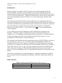
AMNet SOP Site Report A: Each Visit/Weekly Maintenance, 2011-05
Version 1.4
NADP AMNet Standard Operating Procedure Site
Report A: Each Visit/Weekly Maintenance
AMNet SOP Site Report A: Each Visit/Weekly Maintenance, 2011-05
Version 1.4
For information about the National Atmospheric Deposition Program (NADP) contact:
NADP Program Office
Illinois State Water Survey
University of Illinois at Urbana-Champaign
2204 Griffith Drive
Champaign, Illinois 61820-7495
URL: http://nadp.isws.illinois.edu
e-mail: [email protected]
phone: 217-333-7871
2
AMNet SOP Site Report A: Each Visit/Weekly Maintenance, 2011-05
Version 1.4
Abbreviations
AIRMoN
AMNet
AMoN
CAMD
CAMNET
CASTNET
CVAFS
DFU
DQO
GEM
GOM
Hg
LPM
LST
MDE
MDN
MSDS
NADP
NIST
NOAA
NOS
NTN
OSHA
PBM2.5
PO
QA
QAAG
QC
QR
RespFctr
RGM
RPF
SOP
SQL
TGM
UHP
U.S. EPA
USGS
Atmospheric Integrated Research Monitoring Network
Atmospheric Mercury Network
Ammonia Monitoring Network
Clean Air Markets Division
Canadian Atmospheric Mercury Network
Clean Air Status and Trends Network
Cold Vapor Atomic Fluorescence Spectroscopy
Dry Filter Unit
Data Quality Objectives
Gaseous Elemental Mercury (expressed in ng/m3)
Gaseous Oxidized Mercury (expressed in pg/m3)
Mercury, the element (“hydrargyrum”)
Liters per Minute
Local Standard Time
Mercury Deposition Event
Mercury Deposition Network
Material Safety and Data Sheets
National Atmospheric Deposition Program
National Institute of Standards and Technology
National Oceanic and Atmospheric Administration
Network Operations Subcommittee
National Trends Network
Office Safety and Health Administration
Particle-Bound Mercury less than 2.5 μm in diameter (expressed in pg/m3)
NADP Program Office
Quality Assurance
Quality Assurance Advisory Group
Quality Control
Quality Rating
Response Factor
Reactive Gaseous Mercury (expressed in pg/m3)
Regenerable Particulate Filter
Standard Operating Procedure
Structured Query Language
Total Gaseous Mercury
Ultra High Purity
United States Environmental Protection Agency
United States Geological Survey
3
AMNet SOP Site Report A: Each Visit/Weekly Maintenance, 2011-05
Version 1.4
Introduction
Operational checks are required weekly for each site in the NADP Atmospheric Mercury
Network (AMNet). With each visit to the AMNet site, the operator should complete the
operational checks described in this Standard Operating Procedure (SOP) document, Site Report
A: Each Visit/Weekly Maintenance. Though it is not necessary to visit the site on a daily basis or
each week, data should be inspected at least twice a week to ensure proper operation of the
equipment.
The activities described in this SOP focus on the ambient mercury monitoring system, and
ensure that the instrument is free from typical mechanical and operational faults. The SOP and its
associated report identify the components that require maintenance, the consumables required as
part of the maintenance, and the tools needed to perform the maintenance. Maintenance
activities are described in Table 1. Clean, non-talc gloves must be worn when handling the
Tekran equipment.
A copy of the each visit/weekly maintenance report is included in the Appendix to this
document. The Report requires confirmation that specific tasks and measurements are
completed. An “X” in the Done column indicates the task was performed. The date and time of the period impacted by each task should be indicated in the report. Users are
encouraged to use the electronic version of the Report.
The completed report should be named using the naming scheme RSSSSYYYYMM.xls, where R is
the report type (e.g., A, B, C, or D – refer to title of the corresponding SOP), SSSS is the
4-charater site ID, YYYY is the 4-digit year, and MM is the 2-digit designation for the month.
For example, AVT99200912.xls is the each visit/weekly maintenance report that was completed
in December 2009 for VT99. A copy of the report should be submitted to the NADP Program
Office at the end of each month. The information contained in the report, and in all other
reports, is used when validating the data. It is important that all reports are submitted in a timely
manner.
This SOP is not intended to be a troubleshooting guide. Additional information is available in
the user manuals for the instrumentation, the instrument Tech Notes, and from the AMNet site
liaison.
Field Activities
Table 1. Weekly Equipment Maintenance, Field Activities.
None
Maintenance required
None
Consumables required
None
Tools required
4
AMNet SOP Site Report A: Each Visit/Weekly Maintenance, 2011-05
Version 1.4
Completing the Report
Site, Block 1 - Enter the site name and the site ID. Site names are chosen during the site
selection and installation process. The site ID is a four-character code that is assigned by the
NADP Program Office.
1. Site
Name:
ID:
Operator, Block 2 - Enter the name and initials of the person that performed the maintenance,
and to whom questions should directed if there are questions about the report. Three initials
should be used, if possible.
2. Operator
Name:
Initials:
Year/Month, Block 3 - Enter the year and month for the current maintenance period in the form
YYYY/MM, where YYYY is the 4-digit year, and MM is the numeric designation for the month.
.
3. Year/Month (YYYY/MM)
Each Visit Checklist, Block 4
The checklist should be completed each time the AMNet site is visited. Separate boxes are
provided for each task. Place an “X” in the box if the specified criterion is met. Tasks in the
checklist that are shaded green can be verified both on-site and remotely. Tasks in the checklist
that are not shaded can be verified on-site only. Green shaded items must be verified each time
the system is inspected.
5
AMNet SOP Site Report A: Each Visit/Weekly Maintenance, 2011-05
Version 1.4
4. Each Visit Checklist Operator initials: Date 1 2 3 4 5 6 7 X X X X X X X A00 Checks performed remotely A01 2537 date time correct A02 Peak status = OK, OKF, or NP A03 Sample volume 5.0 L (adjustable) A04 Baseline voltage 0.100‐0.250 V A05 Baseline deviations < 0.100 V A06 Calibration zero = 0.000 A07 SPAN RespFctr ≥ 6 x 10⁶ A08 Span difference A vs B ≤ 5% A09 Desorbtion blank C = 0.000 pg/m3 A10 PBM2.5 clear peak A11 GOM clear peak A12 Argon tank ≥ 200 psi A13 Regulator ≥ 30 psi A14 2537 Lamp light off A15 2537 Perm light blinking A16 1130/1135 switches to auto A17 1130 pump switch on A18 1130 pump flow switch to auto A19 1102 warm to touch A20 1102 drierite blue 6
AMNet SOP Site Report A: Each Visit/Weekly Maintenance, 2011-05
Version 1.4
Operator Initials - Place your initials above the day the AMNet equipment was inspected. The
presence of initials in this field will indicate that an operator was at the field site, and that at least
one task was performed.
Checks Performed Remotely – Place an “X” in the appropriate box if the checks are performed
from a remote location rather than at the field site. This indicates to the Site Liaison that some
parameters cannot be verified. Fields that are shaded green must be completed.
2537 Date Time Correct - With the 2537 running, use the left or right arrows to access the
RUN:TIME screen. If the 2537 clock is within 10 seconds of NIST time
(http://www.nist.time.gov/) based on local standard time, place an “X” in the appropriate box.
Refer to the Tekran user manual for instructions to reset the date and time. Include a comment in
the Notes field if the instrument clock is adjusted.
Peak Status = OK, OKF, or NP - Observe the assigned flags below the STAT header, see
column E in Table 1. Place an “X” in the appropriate box if the flags are OK, OKF or NP. If
this condition is not met, contact the AMNet Site Liaison for guidance with the peak status, and
include a comment in the Notes field.
Table 2. Example Tekran 2537 time screen.
A
B
C
D
E
Date
Time
Typ
C
Stat
F
G
H
I
J
K
L
M
AdTim
Vol
Bl
BlDev
MaxV
Area
ng/m3
8/15/2009
10:38:41
CLN
A
NP
0
0
8/15/2009
10:42:16
CLN
B
NP
1
216
0
0.158
0.054
0
0
0
3.66
0.158
0.057
0
0
8/15/2009
10:45:01
CONT
A
OKF
1
300
5
0.158
0.057
0.159
1459
8/15/2009
10:50:01
CONT
B
OK
0
8/15/2009
10:55:01
CONT
A
OK
0
300
5
0.158
0.076
0.169
34242
1.188
300
5
0.158
0.07
0.167
31578
1.176
8/15/2009
11:00:01
CONT
B
OK
0
300
5.01
0.158
0.068
0.169
36015
1.247
0
0.226
Sample Volume 5.0 L - The typical flow rate for the 2537 is 1 liter per minute (lpm). A
collection period of five minutes yields a target volume of 5.0 L. Different flow rates will yield
different target volumes. The measured volume, see column H in Table 2, should be within 2
percent of the target volume. If the measured volume is within 2% of the target volume place an
“X” in the appropriate box. If the condition is not met, contact the AMNet Site Liaison for
guidance with the sample volume, and include a comment in the Notes field.
Baseline Voltage 0.100 – 0.250V – The baseline voltage, column I in Table 2, should be
between 0.100 and 0.250V. Place an “X” in the appropriate box if the baseline voltage is within
this range. Refer to the user manual to adjust the baseline voltage.
Baseline Deviation < 0.100V - If the baseline deviation (column J in Table 2) is less than
0.100V, place an “X” in the appropriate box. If the baseline deviation is greater than 0.100V on
a consistent basis, corrective action should be taken. Contact the AMNet Site Liaison for
guidance with the baseline deviation, and include a comment in the Notes field.
7
AMNet SOP Site Report A: Each Visit/Weekly Maintenance, 2011-05
Version 1.4
Figure 1. Post-calibration instrument output.
Calibration ZERO = 0.000 - Review values from the last calibration. If the value for BlArea
(Figure 1), for both cartridge A and B is equal to 0.000, place an “X” in the appropriate box. If
the condition is not met, contact the AMNet Site Liaison for guidance with the calibration zero,
and include a comment in the Notes field.
SPAN RespFctr ≥ 6x10⁶ – Review values for the last calibration summary. If the value for the
calibration response factor (RespFctr in Figure 1) for both cartridge A and B is greater than 6
million counts, place an “X” in the appropriate box. If the condition is not met, contact the
AMNet Site Liaison for guidance with the calibration response factor, and include a comment in
the Notes field.
SPAN Difference A vs B ≤ 5% - Compare the RespFctr values for cartridges A and B. If the
RespFctr difference is less than 5%, place an “X” in the appropriate box. If the condition is not
8
AMNet SOP Site Report A: Each Visit/Weekly Maintenance, 2011-05
Version 1.4
met, contact the AMNet Site Liaison for guidance with the calibration response factor, and
include a comment in the Notes field.
Desorption Blank C = 0.000 pg/m3 – Review values from the last desorption cycle. The Area
parameter associated with the third 1 flag should have a value of 0.000. If this is true, place an
“X” in the appropriate box. Desorption cycles are discussed in greater detail in the Data
Management SOP. Refer to the user manual or call the AMNet Site Liaison for assistance
correcting problems with the desorption cycle, and include a comment in the Notes field.
PBM2.5 Clear Peak – Greater than 70% of the total peak should be represented in the first
5 minute particulate cycle. In addition, the second particulate cycle should be less than 20% of
the total peak, and the third particulate cycle less than 10% of the total peak. Place an “X” in the
appropriate box if these conditions are met. Refer to the user manual or call the AMNet Site
Liaison for assistance correcting problems with the PBM2.5 peak, and include a comment in the
Notes field.
GOM Clear Peak - Greater than 70% of the total peak should be represented in the first
5 minute GOM cycle. In addition, the second GOM cycle should be less than 20% of the total
peak, and the third GOM cycle less than 10% of the total peak. If these conditions are met, place
an “X” in the appropriate box. Refer to the user manual or call the AMNet Site Liaison for
assistance correcting problems with the GOM peak, and include a comment in the Notes field
Argon Tank ≥ 200 psi – Tank pressure for the argon tank should be greater than or equal to
200 psi. Place an “X” in the appropriate box if this condition is met. Replace the argon tank if
this condition is not met, and document the change in the Notes field.
Regulator ≥ 30 psi - 2 stage regulators and line pressure greater than or equal to 30 psi is
recommended. Place an “X” in the appropriate box if this condition is met. Adjust the regulator
if the condition is not met, and document the change in the Notes field.
2537 Lamp Light Off - The Lamp indictor of the front panel of the 2537 should be off. If this
condition is met, place an “X” in the appropriate box. If the Lamp indicator is on, adjust the
lamp voltage according to the Tekran user manual and Tekran Tech Note TN 2537-013: Lamp
Driver Modification Kit Installation. Document the change in the Notes field.
2537 Perm Light Blinking - The Perm light on the front of the 2537 should be blinking. If this
condition is met, place an “X” in the appropriate box. Contact the AMNet Site Liaison for
guidance if the Perm light is not blinking and include a comment in the Notes field.
1130/1135 Switches to Auto – There are eight switches to the left of the 1130 pump module,
four switches for the 1130 and four for the 1135. All of the switches should all be set to AUTO.
If this condition is met, place an “X” in the appropriate box. If the condition is not met, set all
switches to the AUTO position and include a comment in the Notes field to indicate which
switch(es) was/were corrected.
9
AMNet SOP Site Report A: Each Visit/Weekly Maintenance, 2011-05
Version 1.4
1130 Pump Switch On - The power switch for the 1130 pump is located on the front of the 1130
pump module. The switch should be in the ON position. If this condition is met, place an “X” in
the appropriate box. If the condition is not met, set the switch to ON and include a comment in
the Notes field.
1130 Pump Flow Switch to Auto - The pump flow switch for the 1130 pump is located on the
front panel of the 1130 pump module. The switch should be in the AUTO position. If this
condition is met, place an “X” in the appropriate box. If the condition is not met, set the switch
to AUTO and include a comment in the Notes field.
1102 Warm to Touch - The 1102 air drier removes moisture from the zero air. The drier should
be warm to the touch. This is an indication that the air drier is working properly. If the
condition is met (i.e., the air drier is warm), place an “X” in the appropriate box. IMPORTANT:
Use caution when verifying this as the air drier may be hot. If the condition is not met, contact
the AMNet Site Liaison for guidance and include a comment in the Notes field.
1102 Drierite Blue - The 1102 requires an upgrade (Tekran part number: 80-1102MOD-KIT)
and should include an external drying canister. The canister should be filled with indicating
Drierite. This material changes from blue to rose-red as it absorbs moisture. If the Drierite is
blue, place an “X” in the appropriate box. Otherwise, replace the material and include a
comment in the Notes field.
1130 unit A21 Denuder temperature (sample) 50 °C A22 Denuder temperature (desorb) 500 °C A23 Elutriator heater temperature (sample) 50 °C A24 Elutriator heater temperature (desorb) 75 °C A25 1130 Case temperature 35‐41 °C A26 Sample line temperature 50 °C A27 Pyro temperature (sample) 50 °C A28 Pyro temperature (desorb) 800 °C A29 Part temperature (sample) 50 °C A30 Part temperature (desorb) 800 °C A31 1135 Case temperature 35‐41 °C 1135 unit 10
AMNet SOP Site Report A: Each Visit/Weekly Maintenance, 2011-05
Version 1.4
1130 Denuder Unit
Denuder Temperature (sample) 50°C - The temperature of the denuder should be 50°C during
the sampling cycle. The measurement is made from the denuder PID on the 1130. If this
condition is met, place an “X” in the appropriate box. If the denuder temperature is less than
50°C, contact the AMNet Site Liaison for guidance and include a comment in the Notes field.
Denuder Temperature (desorb) 500°C - Forty-five minutes into the desorption cycle the
denuder temperature should be 500°C. If this condition is met, place an “X” in the appropriate
box. If the temperature is less than 500°C, contact the AMNet Site Liaison for guidance and
include a comment in the Notes field.
Elutriator Heater Temperature (sample) 50oC - The elutriator temperature should be 50°C
during the sampling cycle. If this condition is met, place an “X” in the appropriate box. If the
elutriator temperature is less than 45°C, contact the AMNet Site Liaison for guidance and
include a comment in the Notes field.
Elutriator Heater Temperature (desorb) 75°C - 5 minutes into the desorption cycle, the
elutriator heater should be 75°C. If this condition is met, place an “X” in the appropriate box. If
the elutriator heater temperature is not 75°C, contact the AMNet Site Liaison for guidance and
include a comment in the Notes field.
1130 Case Temperature 35 - 41°C - The set point temperature for the case of the 1130 is
typically 38°C. Except under conditions of severe weather, the unit should be able to maintain a
temperature between 35°C and 41°C. The measurement is made from the case temperature PID
on the 1130. If this condition is met, place an “X” in the appropriate box. If the case
temperature is outside the expected range, contact the AMNet Site Liaison for guidance and
include a comment in the Notes field.
Sample Line Temperature 50°C - The temperature of the sample line should be 50°C during
sampling and desorption cycles. If this condition is met, place an “X” in the appropriate box. If
the sample line is not 50°C, contact the AMNet Site Liaison for guidance and include a comment
in the Notes field.
1135 Particulate Unit
Pyro Temperature (sample) 50°C - The pyrolyzer temperature should be 50°C during the
sampling cycle. The measurement is made from the pyrolyzer PID on the 1135. If this condition
is met, place an “X” in the appropriate box. If the pyrolyzer temperature is less than 50°C,
contact the AMNet Site Liaison for guidance and include a comment in the Notes field.
Pyro Temperature (desorb) 800°C - Twenty five minutes into the desorption cycle, the
pyrolyzer should be 800°C. If this condition is met, place an “X” in the appropriate box. If the
unit has not reached this temperature after 25 minutes, contact the AMNet Site Liaison for
guidance and include a comment in the Notes field.
11
AMNet SOP Site Report A: Each Visit/Weekly Maintenance, 2011-05
Version 1.4
Part Temperature (sample) 50°C - The particulate temperature should be 50°C during the
sampling cycle. The measurement is made from the particulate PID on the 1135. If this
condition is met, place an “X” in the appropriate box. If the particulate temperature is less than
50°C, contact the AMNet Site Liaison for guidance and include a comment in the Notes field.
Part Temperature (desorb) 800°C - Thirty five minutes into the desorption cycle, the
particulate temperature should be approximately 800°C. If this condition is met, place an “X” in
the appropriate box. If the heater has not reached this temperature after 35 minutes, contact the
AMNet Site Liaison for guidance and include a comment in the Notes field.
1135 Case Temperature 35 – 41°C - The set point temperature for the case of the 1135 is
typically 38°C. Except under conditions of severe weather, the unit should be able to maintain a
temperature between 35°C and 41°C. The measurement is made from the case temperature PID
on the 1135. If this condition is met, place an “X” in the appropriate box. If the case
temperature is outside the expected range, contact the AMNet Site Liaison for guidance and
include a comment in the Notes field.
Remarks, Block 6 - Enter any additional comments or explanation regarding the maintenance
activities in this block. Please be concise and clear.
12
AMNet SOP Site Report A: Each Visit/Weekly Maintenance, 2011-05
Version 1.4
Appendix
13
AMNet SOP Site Report A: Each Visit/Weekly Maintenance, 2011-05
Version 1.4
14