1
Osiris 10 manual
Osiris 10
10kW Grid Tie Wind Turbine User Manual
Ver. 1.1
Osiris(Shanghai) Technologies Co., Ltd.
F3, No.3 Building, No.335 Guoding Road,Yangpu District, Shanghai, 200433, China
TO BE INSTALLED, MAINTAINED AND REPAIRED BY TRAINED PERSONNEL ONLY
1
Osiris 10 manual
Congratulations on your purchase and welcome to our family!
Dear Osiris Owner,
Thank you for your purchase of Osiris. You have just selected the most technologically advanced, cost-effective
renewable energy appliance available for a home or small business. We congratulate you on your choice and are
confident you will experience years of dependable service.
Before going any further, please complete and return the enclosed Warranty Registration Card. The conditions of
your warranty are dependent upon the proper installation of Osiris. Furthermore, this will assure you of being kept
up-to-date with the latest developments from Osiris Energy. These include new options, performance tips, updated
software to maximize output and user notices. It is important to know that we do not sell or distribute your information to
any third party. We understand your privacy is important.
If you have any questions or comments, we would like to hear from you. Please call during working hours (MondayFriday - 8:00 am to 4:30 pm Beijing Time). Our telephone number is 0086-21-35030699.
Again, welcome to our family and thank you for investing in the future of wind energy with Osiris.
Sincerely
Osiris Energy Co., Ltd
Enter the serial and model number below
Serial Number
Model Number
2
Osiris 10 manual
Revision History
Revision
Date
Description of Change
Initial
0
19/02/2012
First issue
GH
1
10/05/2012
Minor Amendments and Additions
GH
2
26/05/2012
Tower bolt details Amendments
GH
3
02/08/2012
Tool list additions
GH
4
18/09/2012
Updated system wiring diagram
GH
5
07/11/2012
Minor amendments. Inc tool list changes
GH
6
04/01/2013
Update Condition of maintenance and checking
GH
7
22/02/2013
Updated 3 Month service guidance
GH
8
16/04/2013
Minor Amendment of Package form in 2.5
GH
3
Osiris 10 manual
Important Safety Instructions
READ THESE INSTRUCTIONS IN THEIR ENTIRETY BEFORE INSTALLING OR OPERATING.
● professional installation highly recommended
1) SAVE THESE INSTRUCTIONS. This manual contains important instructions for Osiris that must be followed
during installation and maintenance.
2) Read, understand and respect all warnings.
3) Do not install Osiris around standing water.
4) Do not install Osiris on a windy day.
5) Always obtain a building permit before construction.
6) When moving Osiris or any heavy objects to the site, use a cart to prevent back injury.
7) If unusual noise or abnormal operation is observed from Osiris, turn off the machine and contact authorized service
personnel.
8) Shut Osiris “OFF” if ice accumulates on blades to avoid possible injury resulting from ice flying off blades.
9) This wind generator complies with international safety standards and therefore the design or its installation must
never be compromised.
a. Do not open the inverter cover, doing so without factory authorization will void the warranty.
b. Do not paint the blades.
10) Osiris must be installed in accordance with this manual and local and national building codes. Failure to comply
with the manual and local codes will affect and possibly void your warranty.
In case of any need please contact us at:
Osiris Energy Co., Ltd.
Tel: +86 21 3503 0699
Fax: +86 21 3503 0633
[email protected]
4
Osiris 10 manual
Table of contents
1. Introduction.....................................................................................................................................................................................8
1.1 Technical Specification......................................................................................................................................................8
2. System Description........................................................................................................................................................................9
2.1 Rotor and Blades................................................................................................................................................................ 9
2.2 Generator............................................................................................................................................................................. 9
2.3 Nacelle............................................................................................................................................................................... 10
2.4 Control System..................................................................................................................................................................10
2.5 Package contents..............................................................................................................................................................11
3. Health and Safety........................................................................................................................................................................12
4. Turbine Siting............................................................................................................................................................................... 13
4.1 Planning Permission.........................................................................................................................................................13
4.2 Location..............................................................................................................................................................................14
4.3 Safety Zones..................................................................................................................................................................... 15
4.4 Multiple Installations........................................................................................................................................................15
4.5 Noise.................................................................................................................................................................................. 15
4.6 Shadow Flicker................................................................................................................................................................. 16
5. Mechanical Installation............................................................................................................................................................... 16
5.1 Foundations.......................................................................................................................................................................16
5.2 Tower..................................................................................................................................................................................16
5.2.1 Weights.................................................................................................................................................................. 16
5.2.2 Installation procedure.......................................................................................................................................... 16
5
Osiris 10 manual
5.2.3 Tower Raising....................................................................................................................................................... 20
5.2.4 Earthing.......................................................................................................................................................................... 21
5.2.5 Lightning Protection............................................................................................................................................. 23
5.3 Turbine Head.................................................................................................................................................................... 24
5.3.1 Nacelle Assembly.................................................................................................................................................24
5.3.2 Fitting Blades........................................................................................................................................................ 30
5.3.3 Pitch operation and test.......................................................................................................................................33
5.3.4 crane and hoist operation............................................................................................................................................ 36
6. Electrical System Installation.....................................................................................................................................................37
6.1 General Description......................................................................................................................................................... 37
6.1.1 Osiris Turbine controller...................................................................................................................................... 37
Turning On/Off Voltage for Diversion...................................................................................................................................37
6.1.2 Osiris Dump load.................................................................................................................................................. 39
6.1.3 Osiris Wind Turbine pitch controller.................................................................................................................. 39
6.1.4 Osiris Inverters......................................................................................................................................................40
6.2 Signs and Labels.............................................................................................................................................................. 41
7. Commissioning............................................................................................................................................................................ 43
7.1 Tests................................................................................................................................................................................... 43
7.2 Start-up.............................................................................................................................................................................. 43
7.3 Certification Requirements..............................................................................................................................................44
7.4 Documentation Requirements........................................................................................................................................44
8. Turbine Operation........................................................................................................................................................................45
6
Osiris 10 manual
8.1 Starting Up.........................................................................................................................................................................45
8.2 Running..............................................................................................................................................................................45
8.3 Protective operation......................................................................................................................................................... 47
8.4 Stop the wind turbine....................................................................................................................................................... 48
8.5 Disconnect from the grid................................................................................................................................................. 49
9. Maintenance and Inspections....................................................................................................................................................50
Condition of maintenance and checking...............................................................................................................................50
9.1 Service Schedule..............................................................................................................................................................50
9.2 Annual Inspection.............................................................................................................................................................50
10. Appendix.....................................................................................................................................................................................54
10.1 Appendix 1 - Tool List....................................................................................................................................................54
10.2 Appendix 2 - Troubleshooting Guide........................................................................................................................... 54
10.3 Appendix 3 - Inverter Display Message and Settings............................................................................................... 55
10.4 Appendix 4 - Foundation Sign Off Certificate.............................................................................................................57
10.5 Appendix 5 - Installation Checklist.............................................................................................................................. 58
10.6 Appendix 6 - Installation Sign Off Sheet.....................................................................................................................60
10.7 Appendix 7 - Maintenance / Service Log....................................................................................................................61
10.8 Appendix 8 - Service Report Sheet.............................................................................................................................63
7
Osiris 10 manual
1. Introduction
This manual contains important information concerning your Osiris 10 wind turbine. It is strongly recommended
that you read and familiarize yourself with its contents before installing, operating or maintaining the turbine.
This manual gives a minimum standard that Osiris expects all installations to comply to. Installers are required to
be accredited and members of authorized organization and should ensure that installations comply with all
requirements as part of these accreditations.
Installers are also required to keep abreast of current legislation and should ensure all installations comply with
the most up to date legal requirements. Particular attention should be given to any changes in local Standards
and related requirements. Where changes in this legislation improve on the standards in this document the new
guidance should be taken to overrule the information given in this manual.
The Osiris 10 turbine is a reliable, well engineered machine backed up with an impressive 5 year warranty. At
Osiris we are confident that with proper installation and maintenance the turbine will run successfully and reliably
for many years to come.
1.1 Technical Specification
Turbine Type
Downwind Horizontal Axis
Rated Power Output
10kW @ 9.5m/s
Annual power supplied
Approx 31,166 kWh at 6m/s, or greater & stronger winds
RPM
Variable. 120rpm at max generation
Cut In Wind Speed
3.0m/s
Maximum rated wind speed
59.5m/s
Blades
3 x carbon fiber reinforced glass fiber construction
Speed Control
Passive Pitch and Active Pitch Combined
Additional Safety Systems
Electrical and manual pitch control, automatic brake dump load
Rotor Diameter
9.7m
Head weight
850kGs
8
Osiris 10 manual
2. System Description
The Osiris 10 is a downwind, horizontal axis, low RPM direct drive, permanent magnet wind turbine, designed to
self regulates using a unique passive and active pitch system. With a peak rated output of 10kW at 9.5m/s the
Osiris 10 is specifically designed for high reliability, low maintenance and automatic operation in adverse weather
conditions.
Practical and perfect for supplying electricity to properties such as farms, large residences, offices, businesses and
public buildings, an Osiris wind turbine allows you to generate your own green energy, effectively reducing your
carbon footprint and publicly promoting your commitment to renewable energy.
2.1 Rotor and Blades
The rotor system consists of three molded fiber glass blades and carbon fiber blades. This method of production is
very rare in the small turbine market and is usually only reserved for large MW size turbines. The blades are
manufactured in house under a strict ISO 9001 quality system and are not bought in from an outside supplier. This
ensures we have total quality control at all times and that we are confident that each blade is made to our exacting
standards.
The blades convert the energy of the wind into rotational forces that drive the generator. The blades are carefully
balanced in the factory before delivery to ensure smooth operation of the wind turbine and are supplied as a
matched group. The blades are painted in impact resistant two-pack paint and have carbon fiber reinforced leading
edges to ensure strength and durability.
A passive blade pitch mechanism limits the maximum rotational speed of the rotor. The mechanism consists of 4
springs and mechanical linkages attaching these to the blade root. The pitch setting is factory set and the whole
mechanism is a fail-safe design, meaning that the RPM will be limited to a lower speed if the springs weaken or fail.
This means that the turbine can self limit its top speed even in the heaviest winds or when the load is disconnected.
The wind loading on the blades also acts to orientate the turbine correctly in the wind, removing the need for a tail
vane or yaw motor. This greatly improves the reliability of the turbine and reduces maintenance times and costs.
2.2 Generator
The generator converts the rotational energy of the rotor into electricity. It is built using rare-earth permanent
9
Osiris 10 manual
magnets and has no touching parts or brushes meaning that it is maintenance free.
The permanent magnet generator is designed to produce power at low rotational speeds, eliminating the need for a
gearbox. Again this greatly increases reliability with the added benefit of lower noise and more efficient operation.
The output from the generator is three-phase variable frequency and variable voltage (directly proportional to rotor
speed).
The generator is robust can be physically disconnected from the load at any time without any problems - in this case
the output voltage will rise and the turbine will speed up slightly until the pitch system controls the turbine at its
maximum rpm.
WARNING: A PERMANENT MAGNET GENERATOR PRODUCES A VOLTAGE WHENEVER THE
ROTOR IS TURNING - CAUTION MUST BE EXERCISED AT ALL TIMES TO AVOID ELECTRICAL
SHOCK.
2.3 Nacelle
The nacelle is the main body of the turbine and contains the structural backbone of the wind turbine. It houses and
protects the generator, manual pitch system, yaw bearing and brush gear from the elements. The mainframe is
manufactured from steel and is protected with a hot dip galvanized finish. The removable glass fiber generator cover
enables easy access to the generator and other components, whilst giving a clean and modern finish.
2.4 Control System
The turbine control system is made up of the following parts. Unlike other turbine manufacturers we manufacture
our own control system and inverters, enabling these to be matched exactly to the performance of our turbines. This
increases reliability, improves efficiency and reduces installation time.
Turbine Controller
The turbine controller is the first stage of the control system. This takes the electricity generated by the turbine and
rectifies it ready for the control system inverters. The controller also contains overvoltage protection and can bring in
braking resistors to help control the turbine in high winds.
Turbine Pitch Controller
Osiris pitch controller (Model No.: GPC-01), which supports both automatic pitching and manual pitching; the rated
input voltage is DC24V. GPC-01 can adjust the length of pitch pushing rod to fit the RPM of wind turbine, the wind
turbine could be safeguarded even under storm wind or strong breeze
Braking Resistors
The braking resistors are used to help slow the turbine down when the control system detects that the wind speed is
very high or in case of grid failure. They are only used rarely when required by the control system and do not waste
‘useful’ power: the energy dumped is in addition to the published power curve.
The use of braking resistors ensures that the turbine is always under control and that the inverters are protected
from harmful high voltages in the event of a grid failure.
10
Osiris 10 manual
Inverters
The inverters are custom made to suit the Osiris 10 wind turbine and are matched exactly to its power curve for
optimum efficiency. Setup is quick and easy and there is no complicated programming required.
The inverters take the rectified power from the turbine and construct perfect, grid quality electricity which meets all
requirements of related national grid. The inverters are easy to connect and can be configured for single phase or
three phase installation.
As the inverters are specifically designed for wind turbines rather than PV they have the widest voltage tolerance of
any inverter on the market. They are designed to cope with overvoltage of up to 600V with no adverse effects.
2.5 Package contents
Before you begin, inspect the contents to make sure there is no damage or missing parts.
Package form
Box No.
1
2
3
Wind turbine parts
Quantity
Blade (with mounting plate)
3 pcs
2-1 Generator assembly
1 pcs
2-2 Standard parts
1 set
2-3 Anemometer
1 pcs
3-1 2kW Inverter
6 pcs
3-2 Controller
1 pcs
3-3 Dump load
2 pcs
3-4 Pitch controller
1 pcs
3-5 Transformer
1 pcs
Remark
Size (mm)
4410 x 710 x 630
4410 x 710 x 630
1130 x 1020 x 1100
Packing list and notice:
Your Osiris wind generator is shipped in three boxes (standard parts of tower and naked pack tower are optional)
Box one: rotor blades (three pcs)
● Box dimensions: 4410 x 710 x 630
● Weight: 218 kg
Upon opening, carefully inspect each of the blades to make sure there are no fractures or cracks in the surfaces. Although
the Osiris rotor blades are comprised of a durable carbon fiberglass, damage can occur to the blades during shipping.
Once inspected, be sure to set them away from the construction site and protect them from any damage until they are
ready for assembly.
11
Osiris 10 manual
Box two: Osiris 10 wind generator assembly
● Box dimensions: 2180 x 1090 x 1200
● Weight: 903 kg
Your Osiris comes in several versions in accordance with local utility requirements. Be sure to inspect the package and
confirm you have the right voltage and frequency. If you have ANY questions, call your dealer or the factory before
continuing.
Box three: Osiris 10 electrical & mechanical parts(inverter, controller, transformer, dump load and pitch controller)
● Box dimensions: 1130 x 1020 x 1100
● Weight:: 352 kg
Optional box: standard parts for tower
● Box dimensions: 850 x 50 x 190
● Weight: 325 kg
● Naked pack tower could weight up to 3500kgs, the detail of its specification can be found in Osiris tower manual.
3. Health and Safety
The long term safety of the wind turbine depends on a number of issues that both system designer and installer
must address. Potential hazards need to be identified and eliminated or minimized. This does not just include those
which may be present during installation but also any that may develop over time.
Poor installation can compromise the long term safety of the system. Equally, unsafe site and working conditions
can put installation engineers at risk. Correct design of the system as well as thorough planning of the installation
phase will help to ensure the quality of the installation as well as the safety of the work team.
INSTALLERS NEED TO TAKE NOTE OF THEIR STATUTORY DUTIES UNDER HEALTH AND
SAFETY LAW AND ARE RESPONSIBLE FOR ENSURING COMPLIANCE WITH THE LAW.
The Construction (Design and Management) Regulations may also apply if more than four people will be involved in
the construction work at any one time. The project is notifiable to the Health & Safety organization if it will exceed 30
days or involve more than 500 person-days of work. However, there are exceptions to this.
As part of standard Health & Safety practice, a Risk Assessment should be completed.
Special attention should be given to the following points:
● Due regard should be given to any public rights of way close to the installation site
● The specific local situation should be taken into account, e.g. the likely presence of children or animals
●
Existing site services (e.g. overhead or underground electric cables) should be identified and exclusion zones
defined
● Temporary signs, notices and barriers should be erected
●
The local weather conditions should be considered. Osiris does not recommend the installation of turbines in
wind speeds greater than 6 m/s
● Structural and mechanical installation must be actively managed and supervised by a suitably experienced and
competent person
●
Before each day’s operations commence all workers involved in the works must be fully briefed on the day’s
12
Osiris 10 manual
events and method statements in a toolbox talk. This is to include the identification of danger areas and
potential health and safety issues identified in the risk assessments
● All personnel must wear appropriate personal protective equipment, including high visibility jackets, hard hat
and safety boots
● During installation and maintenance works, an exclusion zone shall be established to prevent persons not
engaged with erection of the turbine from gaining admittance
● Standard precautions for working with rotating machinery should be taken: long hair should be tied back; loose
clothing avoided; rings, necklaces and other jewelry removed
4. Turbine Siting
Osiris project preparation
There are several considerations before you begin the installation process of your Osiris. These considerations are
more important if you intend to connect your machine to the electrical utility. Although Osiris is IEC 61400-2
certified, your local utility and zoning authority may require additional information prior to installation. This chapter
will provide an overview of what to expect when working with your zoning authority.
Working with your Local Zoning Authority
Call your local electric utility, tell them your intentions and ask for their “Interconnection Agreement”. They should
have one. Depending on your utility, the interconnection agreement may be one page or many. Keep in mind that
small utility-connected wind systems are relatively new industries and utility connection requests may be unfamiliar
to them. If you are the first, realize the process may take longer. Osiris Energy has people and tools that may assist
in the process.
Your utility may request documentation demonstrating that Osiris is IEC 61400-2 certified. You can download the
Certificate of Compliance at our website: www.osirisenergy.com
4.1 Planning Permission
The planning authority may impose restrictions on the sitting of a wind turbine. These restrictions are normally due
to two reasons:
● Expected noise output
● Visual impact on the landscape
These restrictions will be particular strong in areas of outstanding beauty. However it should be noted that this does
not mean that planning will not be granted and there are lots of examples of Osiris size wind turbines installed in
these areas.
13
Osiris 10 manual
The customer should be made aware of any restrictions that might occur. In assembling information for the local
planning authority, the latest planning guidance and recommendations should be taken into account.
In support of a planning application, installers should:
● Advise customers to make contact with the local planning authority themselves
● Urge customers to communicate with neighbour and the local community about the project at an early stage
● Provide information to the authority on similar installations (location, equipment type, etc)
● Provide appropriate drawings
● Provide information on noise levels
Osiris can provide a Planning Pack on request which contains a lot of useful information for use during planning
application.
4.2 Location
The ideal site for a wind turbine is on a smooth, rounded and exposed hill-top or rise; one clear of any cliff faces and
many meters from obstructions such as trees and buildings. In practice this very rarely happens. Where it is not
possible to achieve the ideal location the additional risks and Health & Safety considerations must be carefully
weighed.
When locating a wind turbine there is normally a compromise between 5 main factors:
Wind direction: a turbine should be exposed to prevailing winds, i.e. the direction with the best overall combination of
frequency and strength.
Obstacles: wind speed increases with height as the ground and objects close to it disrupt air flow. The 'roughness' of
the ground is a measure of the way obstacles such as trees, buildings and the surface topography act to effectively
slow down the wind. When sitting a wind turbine the installer should take account of possible future obstructions such
as tree growth.
The wind turbine should ideally be placed well clear of any buildings, obstructions and places where the public may
gather.
Turbulence: the flow of the wind is disrupted when it passes over or around objects, so a turbine should be sited to
minimize the influence of obstacles (ideally from all directions). Excessive turbulence may also cause fatigue and
shorten a turbine's life.
Tower height: while greater height will increase energy output (higher wind speed and less turbulence, especially at
sites of greater roughness), practical considerations such as cost and ease of lowering (for maintenance) also need
to be taken into account.
Cable Length: losses from cables will result in a reduction of overall energy output. Cable runs should therefore be
kept as short a possible for optimum performance. The cost of underground cabling may also prove excessive if long
cable runs are planned.
14
Osiris 10 manual
4.3 Safety Zones
The Osiris 10 is designed with safety first are foremost. Despite this, serious mechanical failures could in theory lead
to parts falling from the wind turbine. In preparing a site risk assessment the following safety zones should be taken
into account
Zone
Zone Radius around
turbine
1
Tower Height
2
Tower Height + Blade
Length
Hazard
Falling Part
Guidance
Exclusion zone. In public areas this should
be protected using fencing
Tower Collapse
Part thrown
Low occupancy zone. This area should
generally be kept clear and occupied no
more than 3 person hrs per day
3
50m
Part thrown
Average occupancy zone, typical
occupation of 200 person hours per day
4.4 Multiple Installations
Where multiple installations are intended at a single site extra care should be taken. This includes ensuring that no
turbine is in the wind shadow of another turbine and also that there is adequate space to lower each turbine to the
ground.
Osiris recommended a spacing of a minimum of 3.5 x rotor diameters apart to prevent interference.
4.5 Noise
Modern wind turbines such as the Osiris 10 are designed specifically to minimize noise using a direct drive generator
which operates without a gearbox and has a low rpm whilst maximizing power production. This means that the only
noise is that caused by the swish of the blades in the wind and this is often masked by the background noise in the
area.
However despite this, customers should be made aware of the expected noise levels and given clear and honest
advice about what the noise levels mean.
As a rough guide the minimum distance from properties should be at least 6 x rotor diameters.
15
Osiris 10 manual
4.6 Shadow Flicker
Shadow flicker is an effect caused when the sun passes behind the rotors of a spinning wind turbine and casts a
shadow of the blades over neighboring properties.
The further the away from the wind turbine, the less pronounced the effect becomes. Flicker effects have been
proven to only occur within ten rotor diameters of a turbine.
5. Mechanical Installation
5.1 Foundations
See separate foundation installation guide for details. The foundations should be installed a minimum of two weeks
before turbine installation.
5.2 Tower
5.2.1 Weights
Base Section
Bottom Section
Middle Section
Top Section
12 m Tower
280kg
1170kg
634kg
15m Tower
366kg
1470kg
910kg
594kg
5.2.2 Installation procedure
The tower installation must be carried out with certified lifting slings. A nominated signal man must be used to direct
the lift and ensure the lift is carried out in a controlled and safe manner. The lift area should be cordoned off and no
unauthorized personnel should be allowed to enter.
The importance of leveling the tower can not be underestimated. The Osiris 10 is a downwind passive yaw turbine
and as such can experience yaw problems if the tower is not adequately leveled. Levels should be checked
throughout the tower installation to ensure the tower is not pulled out of level.
The tower installation should only take place in winds less than 6m/s
● Lift parts off vehicle using slings. Ensure that the lift is correctly balanced and that the vehicles lift capacity is
adequate for the work.
● Take tower sections to foundation and layout in the correct positions for assembly.
16
Osiris 10 manual
● Raise up 3 of the M30 foundation nuts (at 120 degrees from each other) by three turns so that the three nuts are
around 2mm higher than the others. Using the spirit level adjust the nut heights until the three nuts are level.
M30 nut
● Lift up the base section and lower over the foundation bolts resting the piece onto the three raised nuts. Make
sure that the hinge section is correctly aligned with the hydraulic cylinder base plate.
● Once the base section is lowered double check the level of the top flange. If the level is more than 0.15 degrees
out of level then readjust the base bolt height to ensure that top flange is level.
● Once the top flange is level install the washers, lock washers and top nuts onto the three leveling foundation bolts.
The nuts should be pre tightened gradually together whilst watching the spirit level, always ensuring that the top
flange remains level.
17
Osiris 10 manual
● Once the three leveling bolts are tightened the remaining nuts can be brought up under the flange. Installer
washers, lock washer and top nuts onto the foundation bolts. Whilst still watching the spirit level bring all M30 bolts up
to 1350Nm using hydraulic torque wrench. It is best to do this by torquing bolts in a cross pattern to ensure the flange
remains level.
● Next install the hydraulic cylinder base pad onto the 4 cylinder foundation bolts. Install the fixing nuts and torque
up to 1100Nm.
●
Lift up the hydraulic cylinder using a sling through the pin hole and move into location above the cylinder base
plate. Insert the fixing pin through the cylinder and base plate and tighten up the nut. When tight it should still be
possible to move the cylinder around the fixing pin.
●
Using a steel trestle it should now be possible to support the cylinder at a 35 degree angle ready for the
installation of the lower tower section.
● Connect up the hydraulic power pack to the lift cylinder using the supplied hoses. Fixing should be tightened to
around 80Nm. The power pack should be connected to the mains supply and be filled with hydraulic oil. It is
recommended that the operation of the power pack and cylinder is confirmed before proceeding with the
installation.
● Lift the lower tower section using the lifting vehicle. The lower section should be installed onto the hinge pin and
the hydraulic cylinder attached to the tower. To help with this the tower should be supported on trestles. The
cylinder can be raised or lowered using the power pack to aid this fixing.
18
Osiris 10 manual
● Lift top section of tower into position and align flanges with the tower. Ensure the cable loops inside the tower are
aligned.
● Bolts flanges together using M24 bolt, washers, and spring washers. Cross fasten the nuts and bring up to 650Nm.
● The tower generator power cable and earthing cable should now be threaded down the tower, ensuring it passes
through each cable loop. The use of thin cable rods is recommended to make this process easier. Please note
that the tower cable is not provided by Osiris.
● The tower is now ready for head installation. Ensure the tower is well supported and is not relying on the lift
cylinder to support its weight. For head installation instructions see the section below.
19
Osiris 10 manual
5.2.3 Tower Raising
● Once the head has been installed the tower can be raised. Start the hydraulic power pack and manually rotate the
pressure valve to raise the tower. When using the hydraulic power pack it is important to keep the flow rate low,
ensuring the flow rate is slow and uniform. If the flow rate is too high the tank may vibrate and jitter which could
cause damage to components.
● Once the tower is raised the final set of bolts can be fastened. Fit with M30 bolts, washers and spring washers,
tighten to 1400Nm. The level should be checked using a digital spirit level against the vertical sides of the tower.
Each flat face should be equally angled.
20
Osiris 10 manual
● After tower installation, remove the cylinder and store safely.
5.2.4 Earthing
The earthing system of Osiris 10 was connected by generator outer wire and main cable through the slip ring. The
grounding should be finish by the customer. When wind turbine and grounding network is completed, the
measurement of grounding resistance must be ≤4Ω. (see Fig. below)
In particular, in order to ensure the reliability of lightning protection system, the infrastructure construction should
abide by following precautions:
A. Earthing network choose galvanized flat iron (min. cross sectional size 50x5. )
B. 3 sets of galvanized flat iron of Grounding network reaching toward the center of foundation, and welding together
with vertical and horizontal steel as a whole.
C. The aforesaid 3 sets of galvanized flat iron reaching out the concrete surface of foundation ring and welding with
the ear plate of tower tube wall.
21
Osiris 10 manual
Osiris 10 electrical system connected to earthing
Each part of the Osiris 10 electrical system (including controller, pitch controller, inverter, dump load and transformer)
has separate grounding point. The following is electrically system connection chart (Fig. 3). Each grounding point of
the component were joined at one point , then connected to grounding network as chapter.2 show with 6mm2 wire.
The exact earthing of the turbine is at the discretion of the system designer and depends on the particular site and
ground conditions. If in doubt about tower earthing please seek professional assistance.
In general the following recommendations should be followed
●
The turbine tower is to be connected to a dedicated earth electrode. An electrode resistance to earth not
exceeding 10 Ohms should be achieved, though may not be justifiable in some cases.
● The earth electrode shall be placed as close as is practical to the tower base and it must be installed in such a
way as to permit periodic inspection. Periodic inspection is important as a failure of this earth termination may
have a serious impact on the system, not least in the transmission of lightning surges.
● The connection between the tower and the tower earth should be made with copper cable (minimum CSA of
16mm2), taking a direct route and avoiding sharp bends.
● Separation between the turbine earth and building earth is to be maintained. This is to ensure that any direct
strikes on the turbine (which may be in a particularly exposed location) are not coupled directly back to the
building.
● The steel wire armor of the turbine output cable should not be coupled in any way to the tower earth and so bring
the turbine earth inside the building. This could occur if a metal junction box is used to join cables within the steel
turbine tower; the metal box would be coupled to the armored sheath by the SWA gland and also coupled to the
tower by direct contact. In such a situation, a non-conductive enclosure must be used.
● An earth wire should be taken up the turbine tower and connected to the earth wire from the nacelle. This earth
wire passes through the earthing brush gear and ensures the nacelle body is connected to the tower earth.
22
Osiris 10 manual
5.2.5 Lightning Protection
The anti-lightning system of Osiris 10 takes the steel bar of the foundation as grounding, the steel bar was welded with
electrical penetration, avails the metallic characteristic of the wind turbine body to connect anchor bolt and steel bar
(of the grounding) - [see fig. 1]
In particular, in order to ensure the reliability of lightning protection system, the infrastructure construction should
abide by following precautions:
A. The electrical penetration of foundation steel bar should be dealt with properly, at least to ensure the outer circle is
penetrated, bridging materials - 12MM round steel, welding length around 150MM.
B. Each corner of the foundation has a down-lead, the down-lead should be 2x16mm or 4x14mm steel bar.
C. The anchor bolt should be installed stably, to ensure down-lead and wind turbine body connected as a whole.
takes the steel bar of the
foundation as grounding,
the steel bar was welded
with electrical penetration,
avails the metallic
characteristic of the wind
turbine tower to connect
anchor bolt and steel bar
(of the grounding) -Fig. 1
The electrical system of Osiris 10 (including controller, pitch controller, inverter, dump load and transformer) has
23
Osiris 10 manual
indoor installation and outdoor electrical cabinet installation,
for the indoor one, it should reach the household
Lightning protection standard; for the outdoor electrical cabinet, it should be connected to the tower Lightning
protection point by 10 mm2 cable.
The design of inverter and other electrical appliance also adopted piezo-resistor B72220S0301K10 in design, to
prevent lightning or the voltage transients of electrical system jeopardizing circuit. The Appendix is the specification
and VDE certificate of the piezo-resistor.
The likelihood of damage may be caused either by a direct strike or through surges induced in cables from a nearby
strike. Tower earthing (see above) provides one element of protection.
a) Dedicated Lightning Protection Systems
If there is a risk of a direct strike, specialists should be consulted about installing a separate LPS
b) Surge Protection
Cabling systems can be designed to provide a degree of surge immunity. The following measures will act to shield the
cables from inductive surges and attenuate surge transmission (by increasing inductance):
● Turbine output cables should be as short as possible, bundled together and not looped
● Long turbine output cables (for example, those over 50m) should have an earth shield, which can be created by
using earthed, armored cable or earthed metal conduit/trunking
Surge suppression devices will give additional protection:
● Where these are fitted to the turbine output cable, they should be attached at the tower base. In the case of long
cable runs, they should be fitted at both ends
● Where surge suppression devices are fitted to protect specific equipment, they should be fitted as close as is
practical to the device
● Surge suppression devices must be electrically safe and pose no electrical fire hazard
5.3 Turbine Head
To enable easy fitting of the nacelle it is usual to lift the tower to a suitable working height, usually with the hub at
shoulder height. This can be done using the hydraulic power pack and cylinder; however once at height it is important
that the tower is supported using trestles near the head end.
NEVER WORK UNDER THE TURBINE WHILST RELYING ON THE LIFT CYLINDER TO HOLD THE
WEIGHT. THE TOWER SHOULD ALWAYS BE SUPPORTED BY OTHER MEANS IN CASE OF LIFT
CYLINDER FAILURE.
5.3.1 Nacelle Assembly
● Unpack the nacelle and inspect for any signs of damage. The enclosed parts should also be checked against the
packing list. If any parts are damaged or missing then please contact Osiris immediately and log as nonconforming
goods. Damaged areas should be photographed as evidence of damage occurring during shipping.
24
Osiris 10 manual
No
Name
Number
1
Wind turbine
1set
2
Manual pitch handle
1 set
3
Anemometer
1 set
4
Standard parts
1 set
Remark
1
2
3
4
● Open up the top cover of the nacelle exposing the brush gear and manual pitch mechanism. Again check for any
internal damage and contact Osiris immediately if there are any concerns.
Lifting point
● Unbolt the lower nacelle cover from the main frame. There are four brackets holding the lower cover on as shown
below.
25
Osiris 10 manual
● Once the brackets are undone the top flange needs to be unbolted from the wooden transportation frame. This
can be quite tricky and we recommend the use of a swivel ended socket spanner suitable for an M16 bolt
(sometimes referred to as a scaffolding spanner).
● Once the lower cover is removed the mainframe and generator can be lifted out of the bottom cover and placed
in a safe location. There are installed eyebolts on the generator and subframe and these should be used along
with rated lifting slings and shackles to get a balanced lift.
● Remove the electric actuator, then mount the M30 lifting ring and sling.
26
Osiris 10 manual
Lifting point
● Next lift the lower cover and slide over the tower top.
● Next the main frame should be lifted using one sling and shackle on the mainframe lifting eye and the 1T chain
block in the generator lifting eye. Once the mainframe is lifted on the ground the chain block should slowly be
lowered to rotate the main frame into a vertical orientation (with nose towards the ground).
● Move the nacelle next to the top tower flange. Align the flanges so that they are approximately 300mm apart. This
is to allow electrical cables to be connected and pitch wire to be threaded down the tower.
27
Osiris 10 manual
● Pull the three power cables and two earth cables from the nacelle flange. These should be connected to the
tower cables using terminal bloc connectors. Also ensure that the tower earth cable is attached to the nacelle
earthing cable (Please note this should be from the tower earth and should be isolated from the building earth).
● Pull the steel rope up from its location in the nacelle and pass over the pulley wheel and through the base of the
mainframe.
● Thread a cable rod down the tower and attach this to the end of the steel wire. Pull the wire through the length of
the tower to the base.
● The manual pitch handle should then be assembled in the base of the tower. Thread the steel wire through this
so that the system will grip the wire and allow it to run over the free moving bolts when turned.
● Once all cables are connected the two flanges should be brought together and fastened using M16x60 hexagon
bolt, washers, and lock washers. These should be fastened to 320Nm.
28
Osiris 10 manual
● Remove the sing and M30 lifting ring, then install the electric actuator. When power is on, a manual pitch and a
return pitch test should be taken by pitch controller to ensure normal pitch operation.
THE CENTRAL AXIS OF φ10.5 HOLE (FOR M10 BOLT) ON THE HOLDER FOR FIXING THE ELECTRIC
ACTUATOR MUST BE IN PARALLEL WITH THE CENTRAL AXIS OF ROTATING SHAFT, OTHERWISE
IT WILL DAMAGE ELECTRIC ACTUATOR AND COMPONENTS OF PITCH MECHANISM WHEN THE
ACTUATOR ACTS.
● Once the flanges are fastened to the correct torque, pull up the bottom nacelle cover and fasten onto the
generator base plate using M10 x 35 bolts and nuts.
● Once the lower cover is installed the turbine is now ready for blade installation.
29
Osiris 10 manual
5.3.2 Fitting Blades
●
Unpack the blades from their packing crate. Be careful when opening to ensure the blades do not fall out. Treat
the blades with exceptional care - especially the leading and trailing edges of the airfoil. The blades are supplied
as a balanced and matched set of three and must be installed together on a single turbine.
● To enable easy fitting of the blades it is usual to lift the tower to a suitable working height, usually with the hub at
shoulder height. This can be done using the hydraulic power pack and cylinder; however once at height it is
important that the tower is supported using trestles near the head end.
NEVER WORK UNDER THE TURBINE WHILST RELYING ON THE LIFT CYLINDER TO HOLD THE
WEIGHT. THE TOWER SHOULD ALWAYS BE SUPPORTED BY OTHER MEANS IN CASE OF LIFT
CYLINDER FAILURE.
● Take care to fit the blades in the correct orientation. Note that the blades turn in a clockwise direction when
viewed from the front of the rotor (i.e. anticlockwise when looking down on the blades). It is possible to fit the
blades in the opposite direction and this could lead to dangerous situations occurring therefore installers should
check carefully before bringing the bolts to full torque.
● Before installing the blades ensure that the blade hub covers are installed on the turbine.
30
Osiris 10 manual
● The blades may be bolted onto any position of the three blade hubs and it is essential to support the blades
weight whilst they are being installed. When connecting the blades to the blade hubs start inserting the M12*50
bolts from the front side of the blade hub and secure with the provided lock nuts and washer. The bolts should be
torqued to 70Nm in two steps: First torque all bolts in an even progression up to 45Nm, then to 70Nm.
● After all three blades have been fitted and bolts torqued wait 30mins before re-checking torque.
● Before install the upper cover of nacelle, the connector of anemometer needs to go through the hole of upper
cover and be fixed with M bolt.
● Connect the connector with anemometer by hand, then install the anemometer on the upper cover of nacelle, one
of bolts on the anemometer must be blocked in the groove and the other must be screwed down by hand, then
rotate 3 cups of anemometer slightly, and check the display of pitch controller to ensure that the anemometer has
31
Osiris 10 manual
output of wind speed data.
● Next the nose cone should be fitted using M8 and M10 bolts. The blade hub covers should also be fastened to
this. Once the nose cone is in place, turn the rotor to check for any interference between nose cover and main
turbine head body.
● The manual pitch should now be tested and checks should be made for interference between blade bolts and the
hub covers. If interference does occur the nose cone should be adjusted.
● Finally the top cover can be fitted and the turbine is now ready for erection.
Pitch handle installation (after tower erection)
● Remove the M12x50 hexagon bolt and M12 locknut from the handle.
● Make the M12x50 hexagon bolt go through the hole from inside to outside at the bottom of the tower circular
opening, and screw down the M12 locknut.
● After remove the M10x50 hexagon bolt and colonnette from the handle, insert the handle into the big hole at the
bottom of the tower circular opening.
● Fix the colonnette and wire rope on the handle with 2 pcs of M10x50 hexagon bolts, then make the wire rope go
through the gap between the colonnette and the handle, and fix the end of wire rope with rope clip (should be at
32
Osiris 10 manual
the lower side of the handle).
5.3.3 Pitch operation and test
● Turn the handle slowly, and the wire rope starts to twist the handle. When turn the handle, the force on it is
increased slowly, as soon as a sudden force is felt, the manual pitch has reached the end. Here the blades should
rotate with an obvious angle. When the wind speed exceeds a proper scope, the blades will reverse after pitch
operation.
● Make the upper hole of disk on the handle aim at M12 blot after pitch operation and insert into it.
AFTER TURN THE HANDLE, WHEN THE WIRE ROPE BECOMES STRAINED, 3 CIRCLES’ HANDLE
TURNING ARE NEEDED FOR A FULL PITCH OPERATION, THE FORCE OF HANDLE TURNING
SHOULD NOT BE GREATER THAN 500N.
● Move the handle out with hand first when return the pitch and then reverse the handle quickly, the blades will be
seen rotating obviously. When the wire rope twisted on the handle is fully cast loosed, the return pitch operation is
finished.
Pitch handle installation
5.3.3.1 Pitch handle installation procedure
A. Dismantle M12x50 hexagon headed bolt and M12 locknut from the pitch handle.
33
Osiris 10 manual
B. Put the M12x50 hexagon headed bolt inside-out through the small hole of the tower, and then fasten the M12
locknut.
C. After dismantle M10x50 hexagon headed bolt and column bar from the handle, insert the handle into the big hole of
the tower.
D. Install wire rope clip on one end of the wire rope, remember to tight it firmly. And fasten another M10x50 hexagon
headed bolt on the other end.
34
Osiris 10 manual
E. Use 2 pcs M10x50 hexagon headed bolt to fasten column bar and the wire rope onto the pitch handle, the wire
rope should thread through the loophole between wire rope and column bar.
5.3.3.2 Manually control the pitch
A. Sway the handle slowly (clockwise or counter- clockwise), the wire rope begins to twine the handle, while the force
on handle will increase, when the force becomes very big suddenly, which means the manual pitching has reaching its
threshold, the rolling of impeller will speed down obviously until stop, and some times counter rolling.
IMPORTAT: AFTER SWAYING THE HANDLE, MANUAL PITCHING WILL REACH ITS THRESHOLD AT 3 TO 4
CIRLE COUNTING FROM THE TIGHTENING OF THE HANDLE, THE FORCE OF SAWYING SHOULD NOT TOO
MUCH (SAMLLER THAN 500N)
B. Keep pitching
After pitching manual (impeller stop or counter rolling), push the handle toward tower slowly, if the small hole on the
handle can’t aligning the bolt, the handle need to be sway backward, until the alignment of the small hole and the
handle, then put the small hole of the handle onto the bolt to prevent it from swaying.
If the impeller keep counter rolling, the handle could be pulled out and change to the position of another small hole to
prevent it from swaying.
35
Osiris 10 manual
C. Pitch restoring
Stir the handle outward, to make it separate from the M12 bolt of the tower completely.
Counter rolling the handle until the wire rope un-tighten completely.
5.3.4 crane and hoist operation
Requirement on crane and hoist
1. The load-bearing of machine should bigger than 12 ton
2. The hanging height should higher than 20m
3. Two separate function wire rope hanger is necessary
4. The load-bearing of hoist cable should bigger than 10 ton
5. The minimum load-bearing of the hoisting part, such as: hoisting pad, hanger and shackle etc is 10 ton.
The operation of crane and hoist
1. All operation should be carried out according to the specific professional regulation issued by relevant authorities,
correct and safety operation is a must.
2. There must not be anybody stand under the arm or the hanging stuff during operation.
36
Osiris 10 manual
6. Electrical System Installation
All work is to be undertaken by experienced, competent and authorised personnel who are fully familiar with standard
working practices within the electrical industry and who are acquainted with the maximum voltages present on the
system being installed.
Live working practices are to be adopted during the initial connection of the turbine to the main output cable
Subsequently, the turbine isolator must be secured open for all other works on the electrical system. Relying only on
the pitch or shorting brake to prevent against shock is not acceptable.
6.1 General Description
The main components of the electrical system are:
6.1.1 Osiris Turbine controller
This provides the interface between the turbine and the grid connect inverter. The Turbine Controller converts the
three phase AC output of the wind turbine to DC for input to the inverter. (transmit power to grid through the inverter.
The rated output power of controller is 20 kw, which includes power transmitted to both inverters and diversion load.
Normally, there is no current through diversion load. When the wind is too strong and the output voltage is too high,
the diversion circuit will work and redundant power will be divided to the load; when the inverter failed to connect grid,
the output voltage of generator will be higher, and then the power from generator will be transmitted to diversion load
by power-leader. By detecting output voltage, power-leader can protect the whole system.
Turning On/Off Voltage for Diversion
User can regulate diversion voltage by switching unit U1. Switch Mode and Diversion Voltage
Switch U1 Mode
Voltage (Vdc)
1, 2 OFF
VON=400, VOFF=300
1 ON, 2 OFF
VON=500, VOFF=400
1 OFF, 2 ON
VON=500, VOFF=400
1, 2 ON
VON=600, VOFF=500
37
Osiris 10 manual
It also has the ability to help control the turbine speed in high winds by bringing in the braking resistors to slow the
turbine down. It does this by detecting a rise in the DC voltage above a preset level. If this is detected the control
system will gradually divert the surplus current to the brake resistors. The current diversion is performed using
advanced high frequency, pulse width modulation (PWM) switching to ensure smooth control of the turbines speed.
The brake resistors are simply resistive elements that are used to dissipate the power generated by the turbine. They
are only used in extreme conditions or in the event of turbine technical problems, however when used they may get
hot. The choice of location should be carefully considered and they should be placed out of reach and at least
500mm from any other risks of fire. An ideal location would be high up on an outside wall.
The three wires of Generator connected to IN1,IN2,IN3; The resistor box’s two white wires shall be connected to
B1,B2, and the yellow/green one connected to G; DC+,DC- are the output dc ends, connected to inverter’s input
terminals; the right terminal G connected to building earth.
There are two dip switches located in the controller. By default these should be set 1on and 2 off. It is important to
check these settings before starting up the turbine.
38
Osiris 10 manual
Dial Switch
Dump Load Switch-on Voltage / V
Dump Load Switch-off Voltage / V
1,2 off
Default: 1on 2 off or
1 off 2 on
1,2 on
310
410
230
330
510
410
6.1.2 Osiris Dump load
Function
● transform the over electric energy of wind turbine
Characteristic of Ginlong inverter:
● Made up of aluminum shell resistors
● Used in small wind turbine system
● Protect electrical equipments when wind speed is grater than rated speed of blade perfectly.
6.1.3 Osiris Wind Turbine pitch controller
Osiris pitch controller (Model No.: GPC-01), which supports both automatic pitching and manual pitching; the rated
input voltage is DC24V. GPC-01 can adjust the length of pitch pushing rod to fit the RPM of wind turbine, the wind
turbine could be safeguarded even under storm wind or strong breeze
The electrical connection of GPC-01 should be abide by the following steps:
1. Make sure the wind turbine stop running and then open the controller cabinet for connecting 3 phase wires.
2. Connecting the relevant terminals to its matching equipment accordingly.
39
Osiris 10 manual
The pitch controller will take different pitching actions according to the wind speed and data collected by setup points.
Setup points
Setup points meaning and action
10m/s
Implement pitching, while >10m/s wind speed
continues for 300s
15m/s
Implement pitching, while >15m/s wind speed
continues for 60s
25m/s
Implement pitching, while >25m/s wind speed
continues for 2s, and then wind turbine will stop
8m/s
Pitching recover, while wind speed drops to
<8m/s, continues for 600s
450Vac
Implement pitching, when detecting the rectified
generator output busbar voltage>450V
20V
Implement pitching, when detecting the battery
voltage<20V
6.1.4 Osiris Inverters
There are three optional scheme in electrical system of Osiris 10. A scheme consists 2 x 5kW inverters in parallel as
a 10KW single phase inverter. B scheme consists 3 x 3.6kW inverters in parallel as a 10.8KW three phase inverter.
C scheme consists 6 x 2kW inverters in parallel as a 12KW three phase inverter.
The inverters must be programmed so that the built in automatic protection system operates at:
● Operating voltage greater than 247V phase to neutral
● Operating voltage less than 207V phase to neutral
40
Osiris 10 manual
● Operating frequency greater than 50.5Hz
● Operating frequency less than 47.5Hz
● Loss of mains / islanding prevention
The inverters are specifically designed to match the output of the Osiris 10 wind turbine and should come
preprogrammed with the Osiris 10 power curve.
Currently, for different scheme in electrical system, a corresponding converter group will be provided for the inverters
to be connected to.
6.2 Signs and Labels
Labeling must be provided at the service termination, meter position and all isolation points in order to indicate
the presence of on-site generation and to show the position of the main AC switch isolator.
At the interconnection point, the following is also to be displayed:
● Circuit diagram
● Summary of protection settings that have been incorporated in the equipment
● A contact telephone number for the supplier/installer/maintainer of the equipment.
● A detailed emergency shutdown procedure
41
Osiris 10 manual
All labels must be clear, easily visible and should be constructed and fixed so as to remain legible and in place
throughout the design life of the system. Example labels are shown below:
42
Osiris 10 manual
7. Commissioning
7.1 Tests
Though Osiris is thoroughly tested at the factory, it is very important to conduct one more test prior to erecting the
tower and operation. Osiris wind turbine should be wired and mounted to the top of the tower. The blades should not
be attached. To do this test, you must have all wires and breakers installed with at least one disconnect switch open
(off). While the tower is in an horizontal position, isolate the controller first, and then check for generator circuit
continuity and insulation to ground with the generator leads disconnected at the turbine connection box.
Resistance between all three lines should be equal. Insulation resistance to ground using a 500V insulation tester
should be more than 2 Meg.
After the tower has been raised check the operation of the manual pitch mechanism.
If the wind speed is less than approximately 6m/s an open circuit test can be performed before connecting the turbine
to the control system. Release the shorting brake and release the pitch to full setting. The turbine should begin
spinning and the rotor should turn freely without significant vibration. If vibration appears excessive further
investigation will be required before installation can be complete.
Whilst the turbine is running off-load check that the voltages between all lines of the output cable are equal using a
digital multimeter. (Due to the varying frequency we recommend that a true RMS meter is used). The voltages
between phases should be approximately equal (they will vary slightly due to gusting of the wind between readings).
A full electrical test of the system should be performed before proceeding with turbine startup.
7.2 Start-up
At the start of commissioning ensure that:
● The turbine shorting switch is on
● The pitch brake is on
● The turbine is isolated from the grid connect inverters
● The grid connect inverter is isolated from the grid
To startup the turbine:
● Turn on the Turbine MCB installed in the customer distribution board
43
Osiris 10 manual
● Turn on the isolator labeled ‘Point of AC Isolation’
● At this stage if the main is within the set parameters the G59 relay should energise (if included)
● Turn on the isolator labeled ‘Point of Turbine Isolation’. We recommended that this isolator is only switched when
the wind turbine is stationary to prolong the life of the unit.
● Switch off the turbine shorting switch
● Release the pitch brake
● The turbine will start to rotate if wind conditions are more than about 4m/s. At first release the turbine may
sometimes take a small time to begin turning due to grease in the bearings.
● The inverter waits until input DC voltage is above a certain level before starting its self test and safety procedures.
At this point the inverters start monitoring grid AC voltage, frequency and impedance. After a few seconds the
GREEN LED starts to flash. If all is OK then it waits 180 seconds and then connects to the grid.
7.3 Certification Requirements
Inspection and testing of the completed system must be carried out to the requirements. Accurate performance testing
of a turbine is only possible where an anemometer reading at the hub height is available. For most small systems,
such data will not be available. Readings from the system display meter will often be the only means to determine how
well the system is working.
7.4 Documentation Requirements
The following must be provided to the customer:
● Turbine foundation specifications - including, where appropriate, an assessment of local ground conditions as well
as the installation requirements, specification of materials, etc
● Drawings, specifications and instructions for assembly, installation and erection
● This installation, maintenance and operation manual
● IEC authorized test certificate if applicable
● Commissioning certificate
● The customer should also be made aware that they should inform their insurance company of the wind turbine
installation
44
Osiris 10 manual
8. Turbine Operation
If very high winds are expected such as wind speed greater than 25m/s it is recommended to manually change the
pitch and apply the short circuit isolator.
If extremely high winds are expected (e.g. 42m/s) we recommended that the turbine is put on brake and the tower
lowered.
During strong winds (wind speed of more than 9m / s) there may be some slight rocking of the tower and turbine head.
This is normal and is expected behavior.
8.1 Starting Up
Remove the short circuit brake
Hold onto the manual pitch lever to prevent sudden movement as the locking bolt is removed. Remove the locking bolt
and then slowly let the handle turn to remove pitch.
When the handle is stationary, remove the rope from the wheel to allow the pitch to be fully returned to normal.
In very high winds or when there is a turbine fault it may be necessary to apply the pitch brake. In these situations
care should be taken as the turning force required will be greater.
8.2 Running
Once running the turbine requires no user intervention. The following gives an overview of the expected wind turbine
behavior.
Behavior in no / low wind:
● Inverter goes into wait mode after disconnecting from grid network
● If wind increases then the inverter will start up. Behavior in Medium Wind up to 12m/s.
● Inverters automatically adjust power output depending on windspeed
Behavior in High Winds above 12m/s:
Inspection Item
Wind Turbine
Inspection Content
The First Three
Months
Every Year
Every 5 Years
Blade
√
√
Blade Bolt M16x60
√
√
Rotor(Hub, Rotating
Shaft etc.)
√
√
45
Osiris 10 manual
Generator
√
√
Engine Base Platform
√
√
Slip Ring
√
√
Pitch Grease XHP223
Tower and
Foundation
Electrical System
Remarks
√
Anemometer
√
√
Electric Actuator
√
√
Nacelle
√
√
Tower
√
√
Tower Fastener
√
√
Foundation Bolt M30
√
√
√
Foundation
√
√
√
Inverter
√
√
√
Controller
√
√
√
Dump Load
√
√
√
Connecting Wire
√
√
√
Battery
√
√
√
1. When a wind turbine experience an extremely high wind (≥42.5m/s), sales
agent or aftersales service agent should inform end users for related enquiry and
inspection.
2. A wind turbine should be fully inspected after a strong wind (≥25m/s) within one
year.
3. The main inspection content:If mechanical components show phenomena as
crack, wear (it will lead to accidents, but a normal running friction not contained),
falling parts, burnt-out generator etc.;If the mechanism operation is abnormal and
if electrical parts show burning-out, open circuit, alarm and other abnormal
phenomena.
● Pitch mechanism will adjust blade pitch to maintain the 10kW output
● If the pitch mechanism can not control the 10kW limit the control system will gradually bring in brake resistors to
control the speed further
46
Osiris 10 manual
8.3 Protective operation
A. Manual pith control
Pitch operation
1). Press the “up” or “down” button on the pitch controller, and choose pitch control on the menu.
Information
Pitch control
Setting
Alarm message
2). Press the “select” button, and select “pitch enable” to activate pitching
Pitch enable
Pitch disable
3). Wait for 30s to finish pitching, normally the impeller will speed down obviously until stop, and some times counter
rolling. (less than 60rpm)
NOTICE: COUTER PITCHING MAY OCCURE, WHEN MANUAL PITHING CONTINUES FOR 20 MINS
Counter pitch operation
2). Press the “up” or “down” button on the pitch controller, and choose pitch control on the menu.
Information
Pitch control
Setting
Alarm message
2). Press the “select” button, and select “pitch disable” to activate counter pitching
Pitch enable
Pitch disable
3). Wait 30s for the finish of counter pitching
B. Manual short-circuit brake
1). Condition
Under normal condition, the rpm of the impeller should be less than 70rpm (the display power of single inverter should
be less than 1kW)
If the rpm of the impeller faster than 90rpm (the display power of single inverter should be less than 1.2kW), the shortcircuit brake may de-functioned.
2). Operation
Turn the short-circuit switch from “OFF” to “ON”, impeller should stop or roll slowly (under heavy wind)
47
Osiris 10 manual
short-circuit switch
If the impeller fail to speed down or stop, the switch should be turned to “OFF”, wait for the speed down timing to
switch it to “ON”
C. Emergency pitch
1). Press the emergency stop button, and the pitch begin to work. The button won’t be bounced back in a short time.
Remark: Emergency pitch does not have a counter pithing effect.
2). Restoration of emergency pitch
Press the emergency stop button again, the button bounce back, and the pitch system will work normally.
8.4 Stop the wind turbine
A. Stop for maintenance
Operation: 1). Normal pitch operation plus short-circuit brake
Or 2). Manual pitch operation plus short-circuit brake
48
Osiris 10 manual
B. Normal stop
Operation: Normal pitch operation
C. Emergency stop
Emergency stop is not recommended, unless the following situation happen
A. The wind turbine run abnormally, while the professional technician is absence.
B. Call the installer for help, presence or absence
C. Call Osiris hot line and follow instruction
Operation: emergency pitch plus short circuit.
D. periodic testing of emergency shutdown/overspeed system
● An emergency shut down test should be operated every six month
● The overspeed system test should be operated every six month, or when the wind speed >50m/s
8.5 Disconnect from the grid
Disconnect from the grid is not recommended, unless the following situation happen
A. Voltage of the grid is abnormal (affect the usage from home appliance) or when the grid line is on fire
B. The operation should be made out by qualified technician
Operation: Turn the main grid tied switch from “on” to “off”
Connection should be restored as soon the situation return to normal.
49
Osiris 10 manual
9. Maintenance and Inspections
Condition of maintenance and checking
A. Temperature between -10℃ ~ 35℃
B. Wind speed < 7.5m/s
C. Not in an unfavorable weather condition such as: heavy raining, storm and hail stone
D. Prepare proper tools and equipments: high-pressure oil gun Grease XHP223
E. Pre-procedure of maintenance
Brake and stop and wind turbine
Lay down the tower
wind turbine checking
CAUTION - PRIOR TO PERFORMING ROUTINE MAINTENANCE, FOLLOW PROCEDURE FOR THE PROPER
SHUTDOWN OF THE WIND TURBINE
9.1 Service Schedule
To ensure your warranty remains valid the Osiris 10 should be maintained according to the requirements below.
Maintenance must be carried out by suitably trained individuals.
This is especially important for turbines located in public places. Osiris installers should ensure a service contract is in
place before installation of a turbine in a public area.
Service’s should be performed to the following schedule:
We recommended that an initial inspection is performed soon after the first high winds experienced by the turbine
(average wind speeds greater than 9m/s) or at 3 months, whichever is sooner.
9.2 Annual Inspection
The Osiris 10 wind turbine requires minimal scheduled maintenance or lubrication, although it is recommended that an
annual inspection is performed to ensure that critical components are not suffering from excessive wear or corrosion.
The generator and pitch bearings are sealed and "lubricated for life" hence require no re-greasing.
The following torque setting should be used when checking fastener tightness:
50
Osiris 10 manual
Torque(Nm)
Wind turbine
other
M8
16
M10
40
M12
70
Grade 10.9
85
M16
230
M20
440
M24
750
M30
1500
M36
2600
M42
3500
Remark: With oiling of bolt surface, the torque value can be reduced by 10%.
Blades
Before lowering the wind turbine, observe the rotor at high speed looking for signs of imbalance. Any unusual noises
could also indicate blade problems and should be investigated further.
After lowering the turbine:
● Check for any damage or cracks to the leading edge.
● Check for cracks in the blade structure, particularly near the blade root. If any damage is noticed which is greater
than surface cracking then the blades will need replacing.
● Check blade bolts for tightness and corrosion. The blade bracket bolts should be 80Nm
Pitch Mechanism
The pitch mechanism needs a visual inspection at all services. It is important that all fasteners are checked for tightness
and that there is no damage on any component.
Nacelle
Before lowering the turbine check that the manual pitch mechanism operates satisfactorily. After lowering the turbine:
● Check for any twist or damage in the power cable.
● Check for free rotation about the yaw bearing. The check the grease on the yaw bearing and if regreasing is
required use a high quality, high temperature grease such as Mobil XHP 223 for lubrication.
● Check the condition of the pitching cable.
● Check the entire machine for damage
51
Osiris 10 manual
General
● Check the paint condition and touch up if necessary.
● Check all turbine fasteners for fit and condition.
● Check all tower fasteners for fit and condition.
● Check the condition of all wiring connections.
● The access cover on the nacelle should be removed to allow inspection of the slip rings and brushes.
Lubrication
A. Lubrication of pitch bearing
● The pitch bearing was installed inside the blade seat, while the nipple was on the blade seat.
● Aim the gun head of high pressure oil gun toward the nipple, lock the gun head and inject the grease into in, volume
of the nipple is 80ml, and the total injection volume should be 240ml.
B. Lubrication of yaw bearing
Unscrew the M8 bolt of cover plate for upper yaw bearing lubrication.
Aim the gun head of high pressure oil gun toward the roller gap of the yaw bearing, inject the grease, greasing the
bearing gap along the ring, usage of the grease = 120ml
Unscrew 2 x M6 bolt of semi-circle plate and dismantle semi-circle plate for lower yaw bearing lubrication.
52
Osiris 10 manual
Aim the gun head of high pressure oil gun toward the roller gap of the yaw bearing, inject the grease, greasing the
bearing gap along the ring, usage of the grease = 150ml
53
Osiris 10 manual
10. Appendix
10.1 Appendix 1 - Tool List
● Grease gun and a high quality, high temperature grease such as Mobil XHP 223 or equivalent. (Maintenance Only)
● Cable installation rods (15m minimum)
● Hydraulic Torque Wrench (up to 2000Nm) or Torque Wrench and Multiplier
● M30 Wrench
● M36 Wrench
● 12” Adjustable Wrench
● Certified lifting slings. Rated at 3T
● Lump Hammer
● Digital Spirit Level with 0.1 degree minimum accuracy
● M30, M36, M42 Sockets
● Electricians Tool Kit
● Mechanical Tool kit
● Metric Socket Set
● Torque Wrench
● Set of flexible headed spanners
● 1 Tonne Chain Block
● 3 x 3 Tonne Shackles
● Theodolite for ensuring tower level
● Axel stands or other support for wind turbine blades
● The six angle wrench for M10, M12, M16, M20 and M24
● The inner hexagon spanner for M8 and M10.
10.2 Appendix 2 - Troubleshooting Guide
Fault
Blade do not turn or turn slowly
Analysis
Blades incorrectly installed.
Manual pitch mechanism activated
Short-circuit brake applied
Electrical short circuit or electrical circuit leads to the control
system of short-circuit;
Power curve not programmed in inverters
54
Osiris 10 manual
Noise from turbine head
Nacelle cover and nose cone are not installed correctly and
are interfering as the turbine turns
The head connectors (bolts, nuts, etc.) are loose
Severe head shaking in low winds
Blades, blade mounting plate, blade shaft or tower bolts are loose
Tower movement
Blades, blade mounting plate, blade shaft or tower bolts are loose
Nose or blade damage
No power
Louder than quoted noise level
Control at a no-load state
Wires and circuit boar failure
Loose fittings or components
Check to see if all fittings and components are tightly fitted
Check for components rubbing
Turbine fails to turn in good wind
Check connections
Visually inspect generator through vents
Remove tower door to check brake
Check ph-ph voltage & resistances across the phases
Turbine turns slowly in good wind
Check connections
10.3 Appendix 3 - Inverter Display Message and Settings
Display Message
Generating
Low wind
Initializing
OV-G-V
UN-G-V
OV-G-F
UN-G-F
G-IMP
NO-G
OV-DC
OV-BUS
UNB_BUS
UN_BUS
UNB2_BUS
SHORT-PRO
INI-PRO
TEM-PRO
Description
Generating electricity
Wind is low and the input voltage does no reach the
lowest point of the inverter input voltage range
Inverter is initializing
Grid voltage is over inverter grid voltage range
Grid voltage is under inverter grid voltage range
Grid frequency is over inverter grid frequency range
Grid frequency is under inverter grid frequency range
Grid impedance high
No grid connected
DC voltage is over inverter input voltage range
Over DC bus voltage
DC bus voltage unbalance
Under DC bus voltage
DC bus voltage unbalance (transient)
Short circuit fault
System initial fault
Over Temperature
GROUND-PRO
Ground fault
The inverters should arrive preprogrammed. If this is not the case the following power curve parameters should be
added using the inverter programming manual.
55
Osiris 10 manual
A scheme consists of 2 x 5kW inverters in parallel as a 10KW single phase inverter.
DC value (V)
30
40
50
60
70
80
90
100
110
120
130
140
150
160
170
180
190
200
210
220
Power (W)
0
0
0
0
0
0
0
0
0
0
0
0
0
0
90
180
390
600
810
1020
DC value (V)
230
240
250
260
270
280
290
300
320
340
360
380
400
420
440
460
480
500
520
540
Power (W)
1230
1440
1650
1890
2070
2310
2490
2730
3150
3570
4050
4380
5000
5000
5000
5000
5000
5000
5000
5000
B scheme consists of 3 x 3.6kW inverters in parallel as a 10.8KW three phase inverter.
DC value (V)
30
40
50
60
70
80
90
100
110
120
130
140
150
160
170
180
190
200
210
220
Power (W)
0
0
0
0
0
0
0
0
0
0
0
0
0
0
90
120
270
420
570
720
DC value (V)
230
240
250
260
270
280
290
300
320
340
360
380
400
420
440
460
480
500
520
540
56
Power (W)
870
1020
1170
1350
1470
1650
1800
1950
2250
2550
2910
3150
3420
3600
3600
3600
3600
3600
3600
3600
Osiris 10 manual
C scheme consists of 6 x 2kW inverters in parallel as a 12KW three phase inverter.
DC value (V)
30
40
50
60
70
80
90
100
110
120
130
140
150
160
170
180
190
200
210
220
Power (W)
0
0
0
0
0
0
0
0
0
0
0
0
0
0
0
70
150
240
320
410
DC value (V)
230
240
250
260
270
280
290
300
320
340
360
380
400
420
440
460
480
500
520
540
Power (W)
490
580
660
750
830
920
1000
1090
1260
1430
1620
1750
1900
2000
2000
2000
2000
2000
2000
2000
10.4 Appendix 4 - Foundation Sign Off Certificate
Osiris Foundation Sign Off Certificate
I CERTIFY THAT THE FOUNDATIONS FOR THE WIND TURBINE AND TOWER (TO BE INSTALLED AT THE
ADDRESS BELOW) ARE INSTALLED AT LEAST THE STANDARDS OUTLINED IN THE OSIRIS INSTALLATION
INSTRUCTIONS.
WHERE CHANGES TO THE SPECIFICATION HAVE BEEN MADE THESE HAVE BEEN MADE WITH THE
APPROVAL OF A REGISTERED CIVIL ENGINEER AND THESE CHANGES DO NOT REDUCE THE
FOUNDATIONS RATINGS IN ANY WAY. WE ALSO HOLD AN APPROPRIATE DESIGN FILE SHOWING ALL
CALCULATIONS MADE AND THIS IS AVAILABLE ON REQUEST.
I UNDERSTAND THAT ANY DEVIATIONS FROM THE OSIRIS SPECIFICATION WHICH ARE JUDGED TO
REDUCE THE EFFECTIVNESS OF THE FOUNDATION DESIGN MAY INVALIDATE OUR WARRANTY.
IF THE FOUNDATION IS FOUND TO BE INCORRECT THEN I ALSO UNDERSTAND THAT I MAY BE CHARGED
FOR ADDITIONAL WORK REQUIRED IN BRINGING THE FOUNDATIONS TO A SUITABLE SPECIFICATION TO
ALLOW FOR TURBINE INSTALLATION
57
Osiris 10 manual
NAME:
SITE ADDRESS:
DATE:
SIGNED
10.5 Appendix 5 - Installation Checklist
Turbine Siting
Is the turbine generally in a safe location? (e.g. without hazard to nearby buildings and structures)
Is there a safe distance (3m) for exposed moving parts?
Are foundations, support structure etc as per our foundation pack?
Are all turbine support structure fixings secure?
Is turbine support structure protected against climbing?
Is lowering equipment suitably stored?
Turbine Installation
Is wind turbine installed to the requirements in this manual?
Is turbine brake system working?
Has brake system been explained to customer?
Are turbine speed and vibration levels acceptable?
Cables
Are turbine electrical connections sound and weatherproof?
Is cable properly laid and sufficient distance from heat sources/ sharp surfaces/edges?
Is cable as our recommendations?
Turbine Isolator
Is the isolator correctly rated?
Is the isolator installed correctly and all electrical connections secure?
Are isolator labels in place?
Turbine Junction Box
Is the junction box installed correctly and electrical connections secure?
Is the junction box in a suitable location?
Are labels in place?
Earthing
Is the turbine structure earth correctly installed?
58
Osiris 10 manual
Inverters
Are the inverters correctly programmed?
Has disconnection on grid failure been checked?
Turbine Metering
Is the metering installed correctly and are all electrical connections secure?
Has the metering system been explained to the customer?
Turbine Controller
Is the controller installed correctly and all electrical connections secure?
Is the controller suitable mounted and adequately ventilated?
Are appropriate labels in place?
Wiring
Is AC cable suitably specified in accordance with BS7671?
Is cabling suitable routed and secured?
Are dual supply notices installed at the service termination, meter position and all points of isolation?
Is suitable AC fault current protection provided at the distribution board?
Is the point of AC isolation suitably labelled?
Documentation
Has an Operation & Maintenance manual been supplied including problem diagnostics, contact
details,
Have manuals for all specific equipment been passed to the customer?
maintenance
schedule/record
sheet,
etc? to the customer?
Has all warranty
information been
passed
Has information on system design been supplied to the customer eg. electrical schematics, civil
works
Has
the installation certificate & test sheet (BS7671) been supplied to customer?
drawings,
calculations
etc?been passed to the customer?
Has signedcable
approval
from DNO
Is the system schematic suitable displayed?
Are the protection settings and installers contact details suitable displayed?
Post-Installation Checklist
BS7671 certification to building control or Part P body?
Commissioning Confirmation to DNO?
Completion of Works Certificate to Customer?
Siged:
Name:
59
Osiris 10 manual
10.6 Appendix 6 - Installation Sign Off Sheet
Osiris 10 Installation Certificate
ACCREDITED INSTALLER COMPANY
COMMSSIONING ENGINEERS NAME
INSTALLER EMERGENCY CONTACT
DETAILS:
MSC ACCREDITATION NUMBER
TURBINE MODEL
OSIRIS 1.6
OSIRIS 10
TURBINE SERIAL NUMBER
GENERATOR SERIAL NUMBER
TOWER TYPE
CUSTOMER NAME
INSTALLATION ADDRESS
FURTHER NOTES:
I CERTIFY THAT THE ABOVE TURBINE WAS INSTALLED IN ACCORDANCE WITH THE INSTALLATION
INSTRUCTIONS, THAT ALL REQUIRED DOCUMENTS AND CERTIFICATES HAVE BEEN PASSED TO THE
CUSTOMER AND THAT THE SYSTEM OPERATION AND SHUTDOWN PROCEDURES HAVE BEEN
EXPLAINED IN DETAIL.
SIGNED:
DATE:
60
Osiris 10 manual
10.7 Appendix 7 - Maintenance / Service Log
Maintenance/Service Log
DATE
DESCRIPTION OF WORK, PROBLEMS IDENTIFIED AND PARTS REPLACED
61
CERTIFIED SERVICE ENGINEER
Osiris 10 manual
62
Osiris 10 manual
10.8 Appendix 8 - Service Report Sheet
CUSTOMER NAME:
TURBINE MODEL
TOWER TYPE
SITE ADDRESS
INSTALL DATE
ORDER NO
S/N
SERVICE TYPE
UNDER WARRANTY?
G= GREEN PASS, A= AMBER PASS – FURTHER WORK MAY BE REQUIRED IN THE FUTURE, R= RED FAIL - FURTHER WORK
REQ’D
CHECKED?
CODE
CHECKED?
TOWER AND FOUNDATION
ELECTRICAL SYSTEM
GENERAL CONDITION
CONTROLLER OPERATION
BOLT TORQUE
CABLE CONNECTIONS
TOWER WELDS
CABLE CONDITION
HYDRAULIC FIXINGS
INVERTER CONNECTION
MANUAL PITCH MECHANISM
INVERTER OPERATION
LIFT CYLINDER
ADDITIONAL WORK
GENERAL CONDITION
NACELLE
MAIN COVER CONDITION
NOSE CONE COVER
YAW BEARING LUBE
BOLT TORQUE
ROTOR
PITCH MECHANSIM
BLADE FIXINGS
PITCH OPERATION
NOTES
FIXINGS
WELD INSPECTION
BEARING LUBRICATION
PITCH SPRINGS
BLADES
BOLT TORQUE
BLADE CONDITION
SIGNED
NAME
DATE
SERVICE ENGINEER
CUSTOMER
63
CODE
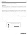
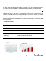
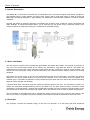
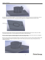
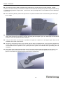
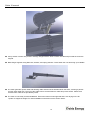
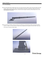
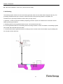
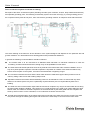
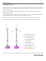
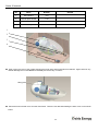
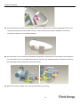
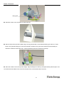
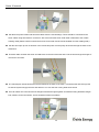
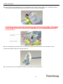
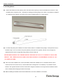
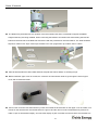
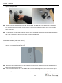
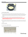
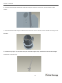
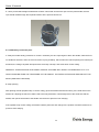
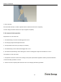

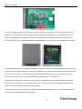
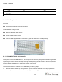
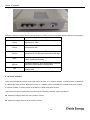
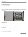
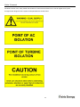
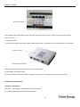
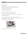
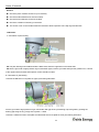
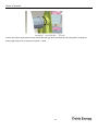


![[B40] RWS-TE2PAFZ39-IR(Videor)](http://vs1.manualzilla.com/store/data/005979657_1-986d79b0350f507a65bc366834e972e4-150x150.png)