1
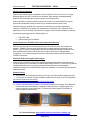
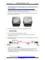
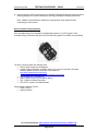
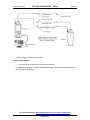
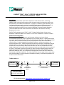
PANDUIT TX6A™ 10GIG™ COPPER CABLING SYSTEM
TESTING PROCEDURES PN524
Introduction
Copper cabling transmission performance depends on cable characteristics, connecting
hardware, patch cords and cross-connect wiring, the total number of connections, and the care
with which they are installed and maintained. To qualify for a PANDUIT System Warranty, postinstallation performance testing must be done using Panduit approved field test instruments to
verify that the installed cabling will meet or exceed the performance requirements of the
designated classification defined in the Commercial Building Telecommunication Standards.
These standards based test results should then be submitted to the PANDUIT Warranty
Department for review.
PANDUIT offers warranty on the TX6A™ 10GIG™ Copper Cabling System for the current
standards, or ANSI/TIA-568B.2-10 to channel, or ISO 11801 Amendment 1 Class EA Ch AMD1.
Channel Test Configuration
The channel test configuration is to be used by system designers and users of data
communications systems to verify the performance of the overall channel. Channel performance
is the most critical to the end user, as this is how their network will perform. The channel includes
up to 90 m (295 ft) of horizontal cable, a work area equipment cord, a telecommunications
outlet/connector, an optional transition/consolidation connector, and two connections in the
telecommunications room. TIA/EIA recommends and ISO requires that the consolidation point be
located at least 5 m (16.4 ft) from the telecommunications room to reduce the effect of multiple
connections in close proximity on NEXT loss and return loss. Per the TIA standard, the total
length of equipment cords, patch cords or jumpers and work area cords shall not be more than 10
m (32.8 ft). If total patch cords are longer than 10 meters, the entire channel length must be derated by the length exceeding 10 meters depending either by 20% or 50% depending on the
patch cord cable type used. The connections to the equipment at each end of the channel are
not included in the channel definition. The channel definition does not apply to those cases where
the horizontal cabling is cross-connected to the backbone cabling. A schematic representation of
a channel can be found below.
TIA/EIA-568B.2-10
Field test
instrument
A
Work
Area
Outlet
C
B
Optional
Consolidation
point
D
E
Horizontal Cross-connect
or Interconnect
Maximum length
B + C = 90 m (295 ft)
A + D + E = 10 m (32.8 ft)
For Technical Support: www.panduit.com/resources/install_maintain.asp
Page 1 of 9
Field test
instrument
© Panduit Corp. 2009
TESTING PROCEDURES
PN524
version 2.4
PANDUIT System Warranty
PANDUIT has different types of warranties. These include the CERTIFICATION PLUS™ System
Warranty and the PAN-NET™ Performance Guarantee. Each warranty is standards based.
PANDUIT will typically provide a system warranty in the following way:
Channel Warranty is based on passing channel test results. (It is recommended to keep the
patch cords installed after testing as there may be variations between patch cords)
As stated previously, passing test results must be obtained using an approved field test
instrument. PANDUIT Corp. places each handheld test instrument thru an evaluation before
approving it for use in the field. This ensures the integrity of the test data submitted for warranty.
Current field testers approved for 10Gig/Category 6A:
•
•
Fluke DTX-1800
Agilent Wirescope Pro N2640A
Testing Required for TIA/EIA CAT6A Channel Operation Warranty
PANDUIT requires that internal channel performance be verified for each link to obtain the
warranty. PANDUIT does not require that field alien crosstalk testing be performed, as the
TX6A™ 10GIG™ Copper Cabling System has been thoroughly lab tested and verified to meet
alien crosstalk requirements under worse case conditions of 6-around-1 tightly bundled
configuration. The customer may wish to perform optional alien testing and this procedure is
included for reference.
Fluke DTX-1800 Series Digital Cable Analyzer
PANDUIT has evaluated the Fluke DTX-1800 Series Digital Cable Analyzer and approves the
use of this tester for the certification of installed 10Gig cabling channels. In order to verify that the
installed cabling will meet or exceed the performance requirements of the designated
classification defined in the ANSI/TIA/EIA Category 6A Standard, it is important that the following
steps are followed.
Channel Testing
1) Verify that your DTX-1800 Series tester has the most up-to-date software (software version
2.12 or better is required). The latest software updates can be found on the Fluke website at:
http://www.flukenetworks.com/fnet/enus/supportAndDownloads/downloadsAndUpdates/?pid=50004
2) Perform a Set Reference procedure in the special functions prior to testing. Fluke Networks
recommends that a Set Reference procedure be performed every 30 days to ensure the
maximum accuracy of the test results. DTX Reference Module part# DTX-REFMOD, is
recommended for Cat6A testing.
For Technical Support: www.panduit.com/resources/install_maintain.asp
Page 2 of 9
© Panduit Corp. 2009
TESTING PROCEDURES
PN524
version 2.4
For detailed instructions on Set Reference procedure, refer to Fluke Network’s DTX-1800
Series Users Manual page 20, on “Setting the Reference for Twisted Pair Cabling”. The link
for the User’s Manual is:
http://www.flukenetworks.com/fnet/en-us/techdocs/Manuals.htm?pid=50004
Note: Fluke Networks also recommends factory calibration once a year to ensure that the
test tool meets or exceeds the published accuracy specifications.
3) Select the Fluke Channel Adapter (# DTX-CHA001A (AxTalk)) and attach them to the DTX1800 Series Main and Remote unit.
4) Select from the following Fluke Test Limts, for which warranty is desired:
•
•
TIA Cat 6A Channel
ISO ClassEA Ch AMD1
5) For channel testing, install all patch cords prior to testing.
Note: PANDUIT recommends for installers to install and test a few channels before
completing the entire system.
6) Begin testing your installed channels with the Fluke DTX-1800 Series Digital Cable Analyzer
and save all test results.
7) Troubleshoot and repair any failing channels. Channels resulting in a PASS* are considered
a PASS and will be acceptable for warranty.
Note: The Fluke HDTDX analyzer and HDTDR test are very helpful when troubleshooting
failing channels. Both can be found on the SINGLE TEST menu and will also run
automatically when a failure occurs. Also make sure that Store Plot Data is set to Extended
under Setup/Instrument settings.
For Technical Support: www.panduit.com/resources/install_maintain.asp
Page 3 of 9
© Panduit Corp. 2009
TESTING PROCEDURES
PN524
version 2.4
8) Submit electronic channel test reports to the PANDUIT Warranty Department with all required
warranty paperwork. A channel warranty will then be given based on passing test results.
Note: PANDUIT recommends for installers to install and test a few channels before
completing the entire system.
Alien Crosstalk Testing (Optional)
Alien Crosstalk testing is not needed for shielded cable systems. For UTP systems, Alien
Crosstalk testing can be done with the Fluke DTX1800 using part# DTX-10GKIT (recommended).
The Alien Test Kit contains the following items:
• DTX-PLA002 Permanent Link adapters
• AxTALK Analyzer Software- (software version 3.0 or newer is required). The latest
software updates can be found on the Fluke website at:
http://www.flukenetworks.com/fnet/enus/supportAndDownloads/downloadsAndUpdates/?pid=50004
• DTX-ATERM Link Terminators (2)
• RJ45 to RJ45 Couplers (2) for channel testing
• DTX- CHA001A channel test heads
• DTX-AXTK1 (2) Alien Crosstalk Modules
Items needed in addition to the kit:
• Patch cords (2)
• Laptop computer
For Technical Support: www.panduit.com/resources/install_maintain.asp
Page 4 of 9
© Panduit Corp. 2009
TESTING PROCEDURES
PN524
version 2.4
Process description:
1. Determine bundles and cables to test:
•
•
Select the longest and shortest links
Apply rules for TIA 568-B.2-10
2. For alien testing, Fluke recommends performing a Set Reference at least once a day.
3. Perform permanent link internal testing to the appropriate standard and save all internals of
the bundle under test to a separate folder. All links must pass internals.
4. Open the AxTalk Analyzer application and click on the new icon to start a new victim file.
Browse for the folder containing the bundle internal tests. Select the file to be used as the
victim link. By saving, the application will automatically title as the victim file as titled from the
internal file selected.
5. Select the appropriate standard from the test limit menu.
6. Select end 1 and PSANEXT from the radio buttons. Run test and follow the directions.
Connect the main and remote as shown below. The Main will always be the victim and the
Remote the disturber. For PSANEXT both units are on the same end and the opposite end
will have terminated plugs. Run a separate disturber test for each non-victim link of the
bundle for end 1, while making the appropriate connection changes. This involves moving the
remote and termination plug to the next disturber.
7. When finished select end 2 and repeat.
8. When finished, select PSAACR-F. Repeat as for PSANEXT but now the main and remote
units will be on opposite ends as shown below. If the patch cord is not long enough, use 2
patch cords and a separate link as the synchronization link.
For Technical Support: www.panduit.com/resources/install_maintain.asp
Page 5 of 9
© Panduit Corp. 2009
TESTING PROCEDURES
PN524
version 2.4
9. When finished, select end 2 and repeat.
Pass/fail determination:
•
Any single failure of any pair will result in an overall fail.
For additional information, see Alien Crosstalk User Manual located under the help tab in the
AxTalk Analyzer application.
For Technical Support: www.panduit.com/resources/install_maintain.asp
Page 6 of 9
© Panduit Corp. 2009
TESTING PROCEDURES
PN524
version 2.4
Approved Test Leads For PANDUIT® MINI‐COM® TX6A™ 10GIG™ Jack Modules and DP6™ 10GIG™ Patch Panels Channel Firmware Version Fluke: Networks DTX‐1800 Software: Series Cable V2.04 or Analyzer later Fluke Networks Website Agilent: WireScope WireScope Pro Pro N2640A Software Agilent 2.1.9 or Technologies later Website Software Version Linkware Software V3.01 or later WireScope Pro (ScopeData Pro II) Software 2.19 or later Calibration Equipment Autotest Test Leads ‐ TIA Cat6A Channel Part # DTX‐ CHA001 Cat6 / Class E Channel Adapter ‐ Cat6A: Channel Part # N2644A‐100 Universal Cat6A Channel SmartProbe Personality Module Comments N/A 1. Consult Fluke Networks' website for the latest Firmware and Software Version. 2. It is STRONGLY RECOMMENDED that the tester is calibrated prior to testing N/A 1. Consult Agilent's website for the latest Software Version. 2. Calibration with the Precision Calibration is STRONGLY RECOMMENDED. 3. Tester holds last calibration. Tester must be recalibrated if using a different DualRemote, upgrading the software, when transitioning from Cat7/Class F copper cable test to Cat6A/Class E or lower performance categories, or after 30 days. 4. Universal Cat6A Channel SmartProbes should be in optimal condition. See owner's manual. For Technical Support: www.panduit.com/resources/install_maintain.asp
Page 7 of 9
TESTING PROCEDURES
© Panduit Corp. 2009
PN524
version 2.4
Appendix A
Standards Limits
TIA Category 6A Channel
Freq.
(MHz)
1
4
8
10
16
20
25
31.25
62.5
100
200
250
350
500
Insertion
Loss (db)
NEXT
(dB)
3
4.2
5.8
6.5
8.2
9.2
10.2
11.5
16.4
20.9
30.1
33.9
40.6
49.3
65.0
63.0
58.2
56.6
53.2
51.6
50.0
48.4
43.4
39.9
34.8
33.1
30.3
26.1
PSNEXT
(dB)
62.0
60.5
55.6
54.0
50.6
49.0
47.3
45.7
40.6
37.1
31.9
30.2
27.3
23.2
Return
Loss
(dB)
19.0
19.0
19.0
19.0
18.0
17.5
17.0
16.5
14.0
12.0
9.0
8.0
6.6
6.0
ACR-F
(dB)
63.3
51.2
45.2
43.3
39.2
37.2
35.3
33.4
27.3
23.3
17.2
15.3
12.4
9.3
PS ACR-F ACR-N
(dB)
(dB)
PSACR-N
(dB)
60.3
48.2
42.2
40.3
36.2
34.2
32.3
30.4
24.3
20.3
14.2
12.3
9.4
6.3
ISO Class EA Ch AMD1
Freq.
(MHz)
1
4
8
10
16
20
25
31.25
62.5
100
200
250
350
500
Insertion
Loss (db)
4
4.2
5.8
6.5
8.2
9.2
10.2
11.5
16.4
20.9
30.1
33.9
40.6
49.3
NEXT
(dB)
65.0
63.0
58.2
56.6
53.2
51.6
50.0
48.4
43.4
39.9
34.8
33.1
30.6
27.9
PSNEXT
(dB)
62.0
60.5
55.6
54.0
50.6
49.0
47.3
45.7
40.6
37.1
31.9
30.2
27.6
24.8
Return
Loss
(dB)
19.0
19.0
19.0
19.0
18.0
17.5
17.0
16.5
14.0
12.0
9.0
8.0
6.6
6.0
ACR-F
(dB)
63.3
51.2
45.2
43.3
39.2
37.2
35.3
33.4
27.3
23.3
17.2
15.3
12.4
9.3
PS ACR-F
(dB)
60.3
48.2
42.2
40.3
36.2
34.2
32.3
30.4
24.3
20.3
14.2
12.3
9.4
6.3
ACR-N
(dB)
61
58.9
52.4
50.1
45.0
42.5
39.8
36.9
28.0
19.0
4.7
-0.8
-10.0
-21.4
For Technical Support: www.panduit.com/resources/install_maintain.asp
Page 8 of 9
PSACR-N
(dB)
58.0
56.4
49.8
47.5
42.4
39.8
37.1
34.2
24.2
16.2
1.8
-3.7
-13.0
-24.5
© Panduit Corp. 2009
TESTING PROCEDURES
PN524
PANDUIT TX6A™ 10GIG™ Copper Cabling System Product List
Part Number
Description
Jack Modules
CJ6X88TG**
CJS6X88TGY
MINI-COM® TX6A™ 10GIG™ UTP Jack Module
MINI-COM ® TX6A™ 10GIG™ Shielded Jack Module
Cable
PUR6X04**
PUR6A04**
PUP6X04**
PUP6A04**
PUL6X04**
PUC6X04**
PSR6004**
PSP6004**
PUFL6X04**
PSL7004**
TX6™ 10GIG™ CMR UTP Copper Cable
TX6A™ 10GIG™ CMR UTP Copper Cable
TX6™ 10GIG™ CMP UTP Copper Cable
TX6A™ 10GIG™ CMP UTP Copper Cable
TX6™ 10GIG™ LSZH UTP Copper Cable
TX6™ 10GIG™ CM UTP Copper Cable
TX6™ 10GIG™ CMR U/FTP Copper Cable
TX6™ 10GIG™ CMP U/FTP Copper Cable
TX6™ 10GIG™ LSZH U/FTP Copper Cable
TX6™ 10GIG™ LSZH S/STP Category 7 Copper Cable
Patch Cords
UTP6X**Y
UTP6A**
STP6X**
TX6™ 10GIG™ UTP Patch Cords
TX6A™ 10GIG™ UTP Patch Cords
TX6™ 10GIG™ STP Patch Cords
Data patch Panels
DP**6X88TGY
DPA**6X88TGY
DP6™ 10GIG™ Modular Punchdown Patch Panel
DP6™ 10GIG™ Angled Modular Punchdown Patch Panel
Modular Panels
CPPL**WBLY
CPPL**M6BLY
CPPLA**WBLY
CP**BLY
CPPL**WRBLY
CPP**FMWBLY
CPPA**FMWBLY
MINI-COM® Modular Faceplate Patch Panels
MINI-COM® M6 Style Modular Faceplate Patch Panels
MINI-COM® Angled Modular Faceplate Patch Panels
MINI-COM® All Metal Shielded Modular Patch Panels
MINI-COM® Recessed Modular Faceplate Patch Panels
MINI-COM® Flush Mount Modular Patch Panels
MINI-COM® Angled Flush Mount Modular Patch Panels
For Technical Support: www.panduit.com/resources/install_maintain.asp
Page 9 of 9
version 2.4