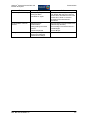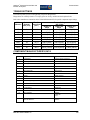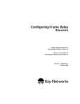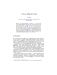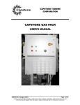
1
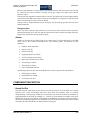
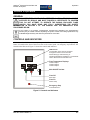
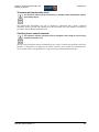
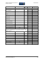
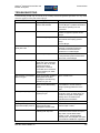
Appendix 9:
User and Operations Manuals for the Landfill Gas to Electricity Project at
the SLS
User and operations manuals that are referred to in this environmental management plan include:
•
Biogas Technical manual - attached;
•
Cat Engine user manual – to be supplied on delivery;
•
Generator operations manual – to be supplied on delivery; and
•
Ener-G Site Operations Manual – Confidential document.
Landfill Gas to Electricity at Shongweni Landfill Site
Basic Assessment Report (S0388)
ix
SYNERGISTICS ENVIRONMENTAL SERVICES
Biogas
2000m³h-1 Enclosed
Ground Flare System and
Booster Set
Technical Manual
Prepared by
Biogas Technology Ltd
Biogas Technology Project No: 3092
Site: Chloorkop
Doc. No: 3092TM Issue: 0.0
-1
2000m³h Enclosed Ground Flare and
Booster Set System
Copyright and Disclaimer
Copyright and Disclaimer
Published by Biogas Technology Limited
All reasonable care has been taken in the preparation of this publication, but Biogas Technology Limited,
its agents and distributors accept no liability for any inaccuracies that may be found. This manual reflects
the state of the product at the issue date below, but modifications may mean that this manual does not
fully reflect your particular installation.
Biogas Technology Limited reserves the right to make changes without notice to both this manual and the
product(s) that it describes. Nothing in this publication should be taken as any offer or commitment on the
part of Biogas Technology Limited unless expressly stated within a contract.
No part of this publication may be reproduced, stored in a retrieval system or transmitted in any form or
by any means electronic, mechanical, photocopying, recording or otherwise without the express prior
written permission of the copyright holder.
Part number 3092 Issue 0.0, 12th November 2007
© Biogas Technology Limited 2007
Biogas Technology Limited
6 Brookside Industrial Estate
Sawtry
CAMBRIDGESHIRE
PE28 5SB
United Kingdom
Telephone:
Fax
email
+44 (0)1487 831 701
+44 (0)1487 830 962
[email protected]
The Biogas name and logo [& any others] are trademarks of Biogas Technology Limited. All other
trademarks and registered trademarks within this publication are the property of their respective owners.
Doc. No: 3092TM Issue: 0.0
ii
-1
2000m³h Enclosed Ground Flare and
Booster Set System
Introduction
Contents
Section 1 Introduction......................... 1-1
Purpose of This Manual ...................... 1-1
The Biogas Enclosed Flare ................. 1-1
Training............................................... 1-1
Maintenance and Support ................... 1-2
Section 2 Safety................................... 2-1
General Safety .................................... 2-1
Electrical Safety .................................. 2-2
Mechanical Safety............................... 2-3
Section 4 Installation and
Commissioning.................................... 4-1
Introduction ......................................... 4-1
Site preparation ................................... 4-1
Site installation .................................... 4-1
Commissioning.................................... 4-1
Section 5 Operation............................. 5-1
General ............................................... 5-1
Controls and Indicators........................ 5-1
HMI Screen ....................................... 5-2
Safety Inspections, Testing, Calibration
and Certification .................................. 2-3
Operation ............................................ 5-3
Section 3 Description.......................... 3-1
Starting ............................................. 5-3
General ............................................... 3-1
Shutting Down................................... 5-4
System Description ............................. 3-1
Emergency Stop ............................... 5-4
Flare Mode ....................................... 3-1
Section 6 Maintenance ........................ 6-1
Power Generation Mode
(Future Provision) ............................. 3-2
Introduction ......................................... 6-1
Ignition.............................................. 3-2
Shutdown.......................................... 3-2
Maintenance Schedules ...................... 6-1
Maintenance Procedures..................... 6-4
Alarms .............................................. 3-3
Checking pneumatic valves
for air leaks ....................................... 6-4
Component Description....................... 3-3
Cleaning flame arresters ................... 6-4
Knock Out Pot................................... 3-3
Draining the KOP .............................. 6-5
Flowmeters ....................................... 3-4
Cleaning the KOP demister element . 6-5
Extraction Fan................................... 3-4
Checking the ignition electrode ......... 6-5
Gas Analysis..................................... 3-4
Thermocouple functionality check ..... 6-7
Main Burner Gas Line ....................... 3-4
Checking louvre control actuators ..... 6-7
Pilot Burner Gas Line........................ 3-4
Section 7 Technical Data .................... 7-1
Flare Stack ....................................... 3-4
General Arrangement and Dimensions 7-1
Control Panel .................................... 3-4
Process and Instrumentation Diagram. 7-2
Telemetry Panel................................ 3-5
Component Designation ...................... 7-3
Gas Analyser Cabinet ....................... 3-5
Operating and Commissioning
Parameters.......................................... 7-4
Compressor ...................................... 3-5
Safety Critical Components............... 3-5
Troubleshooting................................... 7-6
Torque Settings ................................... 7-8
Component Manufacturer’s Data......... 7-8
Doc. No: 3092TM Issue: 0.0
iii
-1
2000m³h Enclosed Ground Flare and
Booster Set System
Introduction
Section 1 Introduction
PURPOSE OF THIS MANUAL
This manual is intended to assist the user in the safe and efficient installation, operation and maintenance
of the Biogas enclosed flare and booster set. It is divided into the following sections:
Introduction (this chapter)
Safety details the safety procedures users should employ to enable the safe installation, operation
and maintenance of the system.
System Description provides the information required to explain to the user the function of the
product.
Options provides information on options and accessories that are available
Installation gives detailed instructions about all operations necessary to install the system and to
bring it up to full working condition.
Commissioning gives detailed initial setting-up procedures and any special tools, test and
calibration equipment required.
Operation contains instructions for the complete operation of the system under normal, emergency
and special conditions
Maintenance includes routine maintenance tasks; tests, checks and inspections; fault diagnosis and
rectification; overhaul instructions.
Technical Data includes all data that the user may need to install, operate and maintain the system.
THE BIOGAS ENCLOSED FLARE
The gas extraction fan and flare stack provide a fully integrated system to extract and flare gas at a
variable rate. The whole system conforms to the Environment Agency Guidance on Landfill Gas Flaring
Version 2.1(November 2002) and TGN05 Guidance for monitoring enclosed landfill gas flares (2004).
The whole system also satisfies the following South African Bureau of Standards (SABS).
Wind Speed:
40m/s as specified in SABS 0160-1989
Seismic Classification:
Zone 2 as specified in SABS 0160-1989, peak ground acceleration of 0.16g
with a 10% probability of being exceeded in a 50 year period.
TRAINING
Biogas provides expert training courses for installation, operation and maintenance of the enclosed flare
and booster set. Training can be provided at Biogas offices in the UK, or at a customer’s premises. To
discuss your requirements, please contact Biogas:
Biogas Technology Limited
6 Brookside Industrial Estate
Sawtry
CAMBRIDGESHIRE
PE28 5SB
United Kingdom
Telephone:
Fax
e-mail
+44 (0)1487 831 701
+44 (0)1487 830 962
[email protected]
Doc. No: 3092TM Issue: 0.0
1-1
-1
2000m³h Enclosed Ground Flare and
Booster Set System
Introduction
MAINTENANCE AND SUPPORT
Full maintenance can be provided for the enclosed flare and booster set by Biogas on either a contract or
call-out basis. Having equipment maintained by Biogas ensures maximum reliability and availability, and
prevents the warranty being invalidated through inadequate maintenance.
Please contact Biogas at the above address to discuss your maintenance requirements.
Doc. No: 3092TM Issue: 0.0
1-2
-1
2000m³h Enclosed Ground Flare and
Booster Set System
Safety
Section 2 Safety
GENERAL SAFETY
This manual is intended to assist the user in the safe and efficient installation, operation and maintenance
of the Biogas enclosed flare and booster set. This equipment must be used in accordance with all safety
procedures described in this manual. The equipment must not be used for purposes other than those for
which it was designed.
Installation, operation and maintenance of the Biogas enclosed flare are restricted to personnel who have
the necessary qualifications to do so within the jurisdiction(s) in which the installation is located. Nothing
in this manual should be taken as contradicting any applicable laws and regulations that have the force of
law within the jurisdiction(s) in which the installation is located.
This manual describes the complete Biogas enclosed flare and booster set installation. Documentation for
components of the installation may also contain safety and operating information and can be found in the
Technical Information File.
Before installing, operating or maintaining the Biogas enclosed flare and booster set, this manual must be
read thoroughly, paying particular attention to all WARNINGS, Cautions and Notes.
WARNINGS ARE USED TO ALERT THE READER TO A PROCEDURE OR
PRACTICE, WHICH IF NOT FOLLOWED CORRECTLY, COULD RESULT IN
PERSONAL INJURY.
Cautions are used to alert the reader to a procedure or practice, which if not
followed correctly, could result in damage to the equipment or ancillary
equipment being damaged or there is risk of environmental damage.
Notes are used to highlight important information that may assist the reader in carrying
out a procedure or in understanding the text.
Incorrect installation or operation, or failure of the user to maintain the equipment in accordance with the
Maintenance information given in this manual, may relieve the Biogas Technology Limited from any or
all responsibility for consequent non-compliance, damage or injury.
The Biogas enclosed flare and booster set must not be used in combination with other equipment unless
such equipment has been expressly designated as compatible equipment by Biogas Technology Limited.
Changes and/or additions to the equipment should only be carried out by Biogas Technology Limited or
by third parties expressly approved by Biogas to do so. Such changes and/or additions must comply with
all applicable laws and regulations that have the force of law within the jurisdiction(s) in which the
installation is located.
Doc. No: 3092TM Issue: 0.0
2-1
-1
2000m³h Enclosed Ground Flare and
Booster Set System
Safety
DO NOT ATTEMPT TO OPERATE THE BIOGAS ENCLOSED FLARE AND
BOOSTER SET UNLESS YOU HAVE READ AND FULLY UNDERSTOOD THE
EMERGENCY STOP PROCEDURE IN THE OPERATING SECTION OF THIS
MANUAL.
BEFORE OPERATING THE BIOGAS ENCLOSED FLARE AND BOOSTER SET
MAKE SURE THAT THE TASKS LISTED IN THE MAINTENANCE SECTION OF
THIS MANUAL HAVE BEEN FULLY COMPLETED. IF THEY HAVE NOT, DO NOT
USE THE EQUIPMENT UNTIL THE MAINTENANCE PROGRAMME HAS BEEN
BROUGHT UP TO DATE. OPERATING THE EQUIPMENT WHEN IT HAS NOT BEEN FULLY
MAINTAINED RISKS PERSONAL INJURY.
IF ANY PART OF THE BIOGAS ENCLOSED FLARE AND BOOSTER SET IS
KNOWN TO BE DEFECTIVE OR MALADJUSTED, DO NOT USE THE EQUIPMENT
UNTIL REPAIRS HAVE BEEN MADE. OPERATING THE EQUIPMENT WITH
DEFECTIVE OR MALADJUSTED COMPONENTS RISKS PERSONAL INJURY.
THE PLANT MAY CONTAIN POTENTIALLY EXPLOSIVE ATMOSPHERES. THE
PLANT MAY GENERATE POTENTIALLY EXPLOSIVE ATMOSPHERE DUE TO
GASES PASSING THROUGH ITS PARTS. PRIOR TO ANY TASKS PERFORMED
ON THE FLARE, THE OPERATOR SHOULD CARRY OUT RISK ASSESSMENT IN
ACCORDANCE WITH CURRENT LEGISLATION AND REGULATIONS. MAINTENANCE
TASKS MAY REQUIRE ISOLATION OF GAS SUPPLY AND ELECTRICAL ISOLATION OF
THE PLANT. ALL ELECTRICAL AND NON-ELECTRICAL EQUIPMENT USED AROUND
THE FLARE SHOULD BE APPROPRIATELY RATED TO RELEVANT AREA
CLASSIFICATION ZONES AND THE POTENTIAL IGNITION SOURCES SHOULD BE
EXCLUDED OR CONTROLLED.
THE PLANT HAS BEEN DESIGNED WITH DUE CONSIDERATION TO THE GUIDANCE
GIVEN IN: IGE/SR/25 "HAZARDOUS AREA CLASSIFICATION OF NATURAL GAS
INSTALLATIONS" ISSUED BY THE INSTITUTE OF GAS ENGINEERS, AND THE ATEX 95
DIRECTIVE 94/9/EC AND DSERA IMPLEMENTATION FOR THE WASTE MANAGEMENT
INDUSTRY (RELEVANT ENVIRONMENTAL SERVICES ASSOCIATION (ESA) INDUSTRIAL
CODES OF PRACTICE). THE PLANT, WITH EXCLUSION OF THE CONTROL PANEL THAT
IS LOCATED IN THE SAFE ZONE, IS CLASSIFIED AS:
II 3 G
ELECTRICAL SAFETY
THE PIPE SECTIONS MAY CONTAIN A FLAMMABLE MIXTURE OF GAS AND AIR.
PRIOR TO ANY TASKS PERFORMED ON THE FLARE, THE OPERATOR SHOULD
CARRY OUT RISK ASSESSMENT IN ACCORDANCE WITH CURRENT
LEGISLATION AND REGULATIONS.
MAINTENANCE TASKS MAY REQUIRE ISOLATION OF GAS SUPPLY AND ELECTRICAL
ISOLATION OF THE PLANT. ALL ELECTRICAL AND NON-ELECTRICAL EQUIPMENT
USED AROUND THE FLARE SHOULD BE APPROPRIATELY RATED TO RELEVANT AREA
CLASSIFICATION ZONES AND THE POTENTIAL IGNITION SOURCES SHOULD BE
EXCLUDED OR CONTROLLED.
Doc. No: 3092TM Issue: 0.0
2-2
-1
2000m³h Enclosed Ground Flare and
Booster Set System
Safety
MECHANICAL SAFETY
DURING VENTING (IF SUCH A MODE IS INCLUDED), A POTENTIALLY
EXPLOSIVE MIXTURE OF GAS AND AIR PASSES THROUGH THE VENT STACK
(IF FITTED) AND/OR FLARE STACK . YOU MUST ENSURE THAT NO SPARKS OR
FLAMES ARE PRESENT, AND YOU MUST MONITOR THE EMISSIONS
CONSTANTLY. AS SOON AS GAS QUALITY IS RESTORED, RETURN THE ENCLOSED
FLARE TO GAS DELIVERY OR FLARE MODE. DURING OPERATION IN THE VENT MODE
THE EXTENT OF THE POTENTIALLY EXPLOSIVE ZONE IS MUCH LARGER IN
COMPARISON TO NORMAL FLARING AND ALL NECESSARY PRECAUTIONS IN
ACCORDANCE WITH DSEAR AND END USER RISK ASSESSMENT NEED TO BE
OBSERVED.
ALL ELECTRICAL AND NON-ELECTRICAL EQUIPMENT USED AROUND THE FLARE
SHOULD BE APPROPRIATELY RATED TO RELEVANT AREA CLASSIFICATION ZONES
AND THE POTENTIAL IGNITION SOURCES SHOULD BE EXCLUDED OR CONTROLLED.
THERE MAY BE NOXIOUS GAS AND DUST WITHIN THE PIPELINE. YOU SHOULD DO
WHATEVER IS POSSIBLE TO AVOID EXPOSURE AND/OR INHALATION OF THESE.
WEAR PROTECTIVE CLOTHING AND A FACE MASK TO AVOID INJURY, IRRITATION
AND INHALATION OF GAS WHENEVER MAINTENANCE PROCEDURES ARE
PERFORMED ON THE SYSTEM.
THERE ARE A NUMBER OF SAFETY CRITICAL COMPONENTS ON THE SYSTEM.
UNAUTHORISED MAINTENANCE OR ADJUSTMENT OF THESE COMPONENTS
MAY AFFECT THE SAFE OPERATION OF THE SYSTEM WHICH COULD RESULT
IN DEATH OR INJURY TO PERSONNEL.THE FOLLOWING COMPONENTS ARE
DESIGNATED AS SAFETY CRITICAL:
FLAME ARRESTERS
UV SENSOR (FLAME DETECTOR)
THERMOCOUPLES
SAFETY INSPECTIONS, TESTING, CALIBRATION AND
CERTIFICATION
It is the responsibility of the user of all equipment obtained from Biogas Technology Ltd., to ensure
compliance with all current legislation regarding the requirement for safety inspections, examinations,
testing, calibration and certification. Biogas Technology Ltd., will not be liable for either the cost or
provision of such services unless contractually agreed.
Biogas Technology Limited plant has been designed to meet the requirements of EC Directive 94/9/EC,
the appropriate EC ATEX Declaration of Conformity is enclosed in the Technical Information File,
together with a copy of the ATEX plate that is mounted on the plant.
Certification applicable to bought out components is enclosed with the suppliers’ information in the
Technical Information File.
Doc. No: 3092TM Issue: 0.0
2-3
-1
2000m³h Enclosed Ground Flare and
Booster Set System
Description
Section 3 Description
GENERAL
Refer to Figure 7-1
The Biogas enclosed flare and booster set system uses sophisticated burner technology to achieve low
noise, low emission burning of landfill gases across a wide range of gas flows from 50 Nm³h-1 to a
maximum standard capacity of 2000 Nm³h-1 with typical minimum turn down ratio 5:1.
A typical system comprises an inlet manifold, a knock out pot with demister, a gas extraction fan, a main
gas burner train, a pilot gas burner train, a power generation gas train, a burner stack and a control and
monitoring system.
Options include GPRS telemetry system, emissions monitoring probe, inlet and stack gas analysis system,
and data logging.
The following describes the enclosed flare system and booster set.
SYSTEM DESCRIPTION
Refer to Figure 7-2.
The following describes the operation of the enclosed gas flare and booster set.
The gas flare has the following modes of operation:
Flare Mode
Power Generation Mode (future provision)
Ignition
Shutdown
Flare Mode
Flare mode is the normal operating mode of the gas flare. Gas from the field is drawn by the extraction
fan/booster through a butterfly valve, a Knock Out Pot (KOP), a slam-shut valve and a butterfly valve.
Total gas flow is measured by the flow meter. The KOP has a wire mesh mist eliminator that removes
liquid from the gas stream. The liquid is collected and drained in the bottom of the KOP. Two level
switches in the KOP monitors the liquid level. If the first level switch is activated then an alarm is
shown on the control panel, if the second switch is activated the alarm will shut down the plant.
Vacuum gauges either side of the wire mesh mist eliminator provide an indication of any blockage in
the mesh.
The gas from the extraction fan discharge is fed via a non-return valve and a butterfly valve and is
monitored for gas quality before being fed to the main burner gas line and the power generator gas
line. The main gas burner is fed via a slam shut valve and a flame arrester to the main burner in the
flare stack. Gas flow to the flare is measured by a flow meter, The slam-shut valve opens after a
successful ignition sequence to allow gas flow to the main burner. The flame arrester prevents flame
flashback from the main burner into the gas train. Pressure gauges either side of the flame arrester
provide an indication of any blockage in the flame arrester.
The flame in the flare stack is monitored by an Ultra Violet (UV) sensor and three thermocouples. The
UV sensor provides a flame present signal to the control panel. The thermocouples provide flare
temperature signals to the control panel. The temperature of the flare is maintained by louvres in the
base of the flare stack. Coarse control is provided by manual louvres that are set up during installation.
Fine control is provided by a motorised louvre that is controlled by the control panel according to the
flare temperature signal from the thermocouples.
Doc. No: 3092TM Issue: 0.0
3-1
-1
2000m³h Enclosed Ground Flare and
Booster Set System
Description
Power Generation Mode (Future Provision)
Power generation mode provides gas to drive a power generator. Gas is drawn from the field in the
same way as flare mode, but the gas is fed through the power generation gas train and not to the
burner. Gas flow to the engines is measured by a flow meter,
Ignition
When gas first flows the main burner slam shut valve is closed and the pilot burner piston valve is
opened allowing a restricted gas flow through to the pilot burner in the flare stack. A gate valve is set
during commissioning to adjust the gas flow rate to the pilot burner.
The pilot burner is ignited by a spark from the igniter. Verification that the pilot is alight is provided
by the UV sensor which sends a flame present signal to the control panel. After a short delay to allow
the pilot burner flame to stabilise the main burner slam shut valve is opened allowing gas to flow to
the main burner. The pilot flame ignites the main burner and when the temperature of the main flare
reaches a pre-determined level the pilot burner slam shut valve closes and the pilot burner is
extinguished.
If high methane content in the landfill gas creates a too rich mixture that is difficult to ignite, a small
volume of compressed air is injected into the pilot line immediately prior to the pilot burner gas via a
flame arrester and pressure control valve. Compressed air is only added during the ignition cycle. This
feature is optional.
Should the pilot burner fail to ignite within 5 seconds the igniter will be switched off for five seconds
before another ignition attempt is made. This 5 second on/5 seconds off sequence of ignition attempts
will continue up to a maximum of 5 minutes. A maximum of 3 ignition cycle attempts is allowed
before an auto shutdown will be activated.
Shutdown
There are 3 ways of shutting the gas flare:
Manual
Automatic
Emergency
Manual Shutdown
When the gas flare is stopped by selecting OFF on the HMI screen the gas inlet and main burner
slam-shut valves will close and the extraction fan will be switched off cutting off the gas supply to
the main burner.
Auto Shutdown
The following conditions will cause the gas flare to shutdown automatically:
High stack temperature
Ignition cycle fail
Extraction fan trip
High high liquid level in KOP
Gas inlet slam-shut valve failure
Main burner slam-shut valve failure
Thermocouple 1 failure
Thermocouple 3 failure
Doc. No: 3092TM Issue: 0.0
3-2
-1
2000m³h Enclosed Ground Flare and
Booster Set System
Description
When an auto shutdown is invoked the gas inlet and main burner slam shut valves will close and
the extraction fan will be switched off cutting off the gas supply to the main burner and the
generator engine.
Following an auto shutdown a manual restart is required. The alarm must be acknowledged and the
system reset on the HMI screen before a restart can be attempted. The temperature of the flare stack
must be less than 300°C before a restart is enabled.
If the gas flare is stopped manually (off or emergency stop pressed) the gas flare will have to be
restarted manually.
Emergency Stop
When any of the emergency stop buttons are pressed the gas inlet and main burner and power
generation slam shut valves will close and the extraction fan will be switched off cutting off the gas
supply to the main burner and the generator engine.
Alarms
Alarms are provided on the HMI screen on the control panel. For full information on the HMI
screen refer to the Technical Information File. The following alarms also generate an auto
shutdown:
High/low stack temperature
Ignition cycle fail
Extraction fan trip
High high liquid level in KOP
Gas inlet slam-shut valve failure
Main burner slam-shut valve failure
Thermocouple 1 failure
Thermocouple 3 failure
Flare off and flame detected
The following alarms are provided on the HMI screen but do not generate an auto shutdown.
Thermocouple 2 failure
High liquid level in KOP
Gas analyser low flow
COMPONENT DESCRIPTION
Refer to Figure 7-2.
Knock Out Pot
The KOP removes liquid from the gas stream. Gas from the field is fed to the KOP via a manual
butterfly valve, a flow conditioning plate and a flow meter. The butterfly valve is set during
commissioning. Vacuum gauges measure the vacuum either side of the wire mesh mist eliminator. A
significant difference between the readings (15 – 20 mbar g) would indicate a blockage in the mesh.
Manual ball valves allow for isolation of the gauges for maintenance. An analysis point is provided for
connection of sampling equipment. Two manual ball valves in the drain line allow the coalesced liquid
collected in the base of the KOP to be drained without venting gas.
Doc. No: 3092TM Issue: 0.0
3-3
-1
2000m³h Enclosed Ground Flare and
Booster Set System
Description
Flowmeters
Flowmeters are fitted to the gas inlet, the main burner gas train and the power generation gas train.
The flowmeters measure the flow rate of the gas. They comprise a flow conditioning plate in the
pipeline with a thermal mass flow meter for flow measurement.
Extraction Fan
The extraction fan draws gas from the field at maximum 2000 Nm³h-1. Flexible connections to the
main pipeline reduce vibration effects on the pipeline. A pneumatic slam-shut valve and manual
butterfly valve are fitted to the inlet of the extraction fan. A non-return valve and a manually butterfly
valve are fitted to the outlet of the extraction fan.
Gas Analysis
The gas data analyser is connected to the system at this point for gas sampling. Concentrations of
methane, carbon dioxide and oxygen are measured and fed into the HMI screen.
Main Burner Gas Line
Gas flow to the main burner is controlled by a pneumatic slam shut valve (SSV). The SSV is opened
by a control signal from the Control Panel when gas flow to the main burner is required and safety
conditions are satisfied. Compressed air is provided by the compressor. A flame arrester, a safety
critical component, prevents the transmission of flames from the main burner while permitting the gas
to flow. Pressure gauges upstream and downstream of the flame arrester are provided to indicate
blockages in the flame arrester element.
Pilot Burner Gas Line
Gas flow to the pilot burner is controlled by a manual control (gate) valve and a pneumatic slam shut
valve (SSV). The manual control valve controls the amount of gas flow tapped from the main burner
line. The SSV is opened by a control signal from the Control Panel when gas flow to the pilot burner
is required during the ignition sequence. Compressed air is provided by the compressor. A flame
arrester, a safety critical component, prevents the transmission of flames from the main burner while
permitting the gas to flow. Pressure gauges upstream and downstream of the flame arrester are
provided to indicate blockages in the flame arrester element. Two manual ball valves in the drain line
allow the liquid to be drained from the burner lines without venting gas. If required compressed air can
be added to the pilot burner gas during ignition via a manually adjusted control valve and a flame
arrester. The control valve is set up during installation to achieve the correct methane/O2 mix.
Flare Stack
The flare stack contains the main and pilot burner, igniter, UV sensor, thermocouples, manually
adjusted louvres, automatically adjusted louvre and emission monitoring ports. The louvres provide
flame temperature control. The manual louvres are set up during installation and the automatic louvre
is set by the control panel according to the output from Thermocouple 2. The UV sensor and the
thermocouples are safety critical components. The UV sensor detects the presence of a flame and
thermocouple 3 monitors the flame temperature. All thermocouples provide a high temperature
shutdown signal.
Control Panel
The power and control components are contained in an air conditioned IP55 cabinet with a hinged and
lockable outer door. An emergency stop switch is located on the outer door.
Doc. No: 3092TM Issue: 0.0
3-4
-1
2000m³h Enclosed Ground Flare and
Booster Set System
Description
Telemetry Panel
The telemetry components are contained in the control panel cabinet. The following telemetry data is
transmitted:
Flare temperature
Exhaust gas sample temperature
Gas flow rate (flare)
Gas temperature (flare)
Gas flow rate (power generation)
Gas temperature (power generation)
Gas flow rate (total)
Gas temperature (total)
CH4 concentration (inlet gas)
CO2 concentration (inlet gas)
O2 concentration(inlet gas)
N2 concentration (inlet gas)
CH4 concentration (exhaust gas)
CO2 concentration (exhaust gas)
Gas Analyser Cabinet
The gas analysis equipment is contained in an air conditioned IP65 cabinet with a hinged and lockable
door.
Compressor
The compressor is started when the main electrical isolator on the control panel is set to ON. The
compressor provides compressed air to the slam shut valves.
Safety Critical Components
THERE ARE A NUMBER OF SAFETY CRITICAL COMPONENTS ON THE
SYSTEM. UNAUTHORISED MAINTENANCE OR ADJUSTMENT OF THESE
COMPONENTS MAY AFFECT THE SAFE OPERATION OF THE SYSTEM
WHICH COULD RESULT IN DEATH OR INJURY TO PERSONNEL.
The following components are designated as safety critical:
Flame arresters: prevents transmission of flames from the burner back into gas line
UV sensor: provides a flare present signal
Thermocouples: measure the flare temperature at various points in the flare stack
Doc. No: 3092TM Issue: 0.0
3-5
-1
2000m³h Enclosed Ground Flare and
Booster Set System
Installation and Commissioning
Section 4 Installation and Commissioning
INTRODUCTION
The Biogas enclosed flare will be installed by Biogas personnel.
DO NOT ATTEMPT TO INSTALL THE BIOGAS ENCLOSED FLARE AND BOOSTER
SET UNLESS YOU HAVE READ AND FULLY UNDERSTOOD THE SAFETY
INFORMATION IN SECTION 2 OF THIS MANUAL.
SITE PREPARATION
Before the enclosed flare and booster set can be installed, a reinforced concrete base must be prepared to
support the assembly. As the requirements vary between sites and systems, the specifications of this base
will be supplied by Biogas.
The system will also require a three-phase electricity supply and pipework for the gas supply. The
specifications of electricity supply will be advised by Biogas prior to installation.
If a telemetry system is fitted, an appropriate connection from the control panel to a telephone line,
GPRS, satellite or any other communication device will be required.
Details of all these requirements will be given by Biogas after the initial site survey.
SITE INSTALLATION
Biogas personnel will install and connect the enclosed flare. If the system has to be moved or reinstalled,
please contact Biogas for advice.
COMMISSIONING
The Biogas installation team will perform all final checks and commissioning to ensure that the system is
functioning correctly. They will also configure the system to perform within specification.
Any unauthorised adjustment of the system or operating the plant prior to
commissioning and handover may invalidate the Biogas warranty.
Doc. No: 3092TM Issue: 0.0
4-1
-1
2000m³h Enclosed Ground Flare and
Booster Set System
Operation
Section 5 Operation
GENERAL
ALL OPERATORS MUST HAVE ATTENDED A FULL TRAINING COURSE
SUPPLIED BY BIOGAS, AND MUST POSSESS A CERTIFICATE TO CONFIRM
THIS. DO NOT ATTEMPT TO OPERATE THE BIOGAS ENCLOSED FLARE
UNLESS YOU HAVE READ AND FULLY UNDERSTOOD THE SAFETY
INFORMATION IN SECTION 2 OF THIS MANUAL AND THE EMERGENCY STOP
PROCEDURE BELOW.
If the system is not properly commissioned, operated and maintained, the manufacturer's
warranty may be voided or limited. Operating the system outside of the design parameters may
invalidate Biogas warranty and affect the performance of the flare.
CONTROLS AND INDICATORS
All the controls and indicators necessary to operate the flare are on the control panel. The emergency stop
button is located on the front of the access door to the control panel. An emergency stop button is also
located on the flare stack. Figure 5-1 shows the controls and indicators.
HMI Screen
The operation of the plant is controlled
through this screen. The screen also
allows setting up and monitoring of
operating parameters and alarms. For full details
refer to the Technical Information File.
Flare Temperature Displays
F1
F1
F1
ON
OFF
Thermocouple 1
Thermocouple 2
Thermocouple 3
Main ON/OFF Isolator
Flare Off
Red Lamp
Flare On
Green Lamp
Emergency Stop
On External Door
Figure 5-1 Controls and Indicators
Doc. No: 3092TM Issue: 0.0
5-1
-1
2000m³h Enclosed Ground Flare and
Booster Set System
Operation
HMI Screen
The HMI screen provides the following status information:
Flare start-up status
Landfill gas concentrations
Pilot re-light count
Pilot gas ON/OFF status
Igniter ON/OFF status
Pilot proved status
Extraction fan status
Slam-shut valve status
Flame proved status
Extraction fan hours run
Flare operating temperature
Temperature controller output status
Gas inlet flow rate
The HMI screen provides the following control functions:
System control (Local – Off – Remote)
Extraction fan control (Hand – Off – Auto)
Temperature control loop for louvre automation
Temperature controller setpoint
Reset switch
Alarm acknowledge
The following auto shutdown alarms are displayed on the HMI screen:
High stack temperature
Ignition cycle fail
Extraction fan trip
High high liquid level in KOP
Gas inlet slam-shut valve failure
Main burner slam-shut valve failure
Thermocouple 1 failure
Thermocouple 3 failure
Flare off and flame detected
The following alarms are provided on the HMI screen but do not generate an auto shutdown.
Thermocouple 2 failure
Doc. No: 3092TM Issue: 0.0
5-2
-1
2000m³h Enclosed Ground Flare and
Booster Set System
High liquid level in KOP
Gas analyser low flow
Operation
OPERATION
Starting
1. Check that there is no maintenance work being carried on the system.
2. Inspect the system for signs of damage and that it is safe to operate. Any damage must be
rectified before start-up.
3. Ensure the field gas supply is connected
4. Set the system main electrical isolator to ON.
5. Check the compressor is running and there is an air supply to the system.
6. Ensure that the gas quality is within the flare operating range
(25 – 60% vol. methane and < 5% vol. oxygen).
Local Operation
1. On the HMI screen system control select LOCAL.
2. Select START FLARE and observe start sequence. Check the green ON lamp is lit.
3. If the system fails to ignite check line gas quality is within the operating quality range:
(CH4 : 25 – 60% v/v, O2 < 5% v/v)
Ignition Failure
1. If the ignition sequence fails to ignite the pilot gas or the flare fails to reach operating
temperature within a preset time the system will shut down. The HMI screen will indicate an
ignition failure.
2. Reset the system by pressing the STOP function on the HMI screen and the cancel the alarm.
3. Press the START function on the HMI screen to restart the ignition sequence.
4. If the system still fails to ignite check that the gas quality is within the operating quality range.
Automatic Restart
If the system shuts down automatically (high stack temperature, ignition cycle fail, fan trip, highKOP level) the system will restart automatically after a 30 minute shutdown period.
Three automatic restarts will be attempted before a reset is required. To reset the system press the
STOP function on the HMI screen.
To prevent an automatic restart after an automatic shutdown, press the STOP function on the HMI
screen.
Remote Operation
1. The system can be operated remotely by telemetry. On the HMI screen system control select
REMOTE.
2. The flare will start when a remote start signal is received via the telemetry system.
Doc. No: 3092TM Issue: 0.0
5-3
-1
2000m³h Enclosed Ground Flare and
Booster Set System
Operation
Shutting Down
1. To stop the system in a controlled manner (not an emergency), on the HMI screen select STOP
FLARE. The system will run down and the gas inlet and main burner slam-shut valves will
close
2. Set the system main electrical isolator to OFF.
3. Check the compressor has stopped and the extractor fan has stopped rotating.
Emergency Stop
1. To stop the system in an emergency press one of the EMERGENCY STOP buttons (control
panel or flare stack).
Doc. No: 3092TM Issue: 0.0
5-4
-1
2000m³h Enclosed Ground Flare and
Booster Set System
Maintenance
Section 6 Maintenance
INTRODUCTION
The Biogas enclosed flare is a high performance gas delivery and disposal system that requires controlled
maintenance if it is to operate at peak performance. All maintenance and servicing must be performed by
staff who have been trained and certified as competent by Biogas.
If the system is not properly maintained, the manufacturer's warranty may be invalidated or limited. This
may also affect the performance of the flare.
ALL MAINTENANCE AND SERVICE STAFF MUST HAVE ATTENDED A FULL
TRAINING COURSE SUPPLIED BY BIOGAS, AND MUST POSSESS A
CERTIFICATE TO CONFIRM THIS. DO NOT ATTEMPT TO MAINTAIN THE BIOGAS
ENCLOSED FLARE UNLESS YOU HAVE READ AND FULLY UNDERSTOOD THE
SAFETY INFORMATION IN SECTION 2 OF THIS MANUAL AND THE EMERGENCY STOP
PROCEDURE IN SECTION 5.
BEFORE ANY MAINTENANCE IS CARRIED OUT ON ANY PART OF THE SYSTEM,
IT IS ESSENTIAL THAT THE FLARE AND BLOWER OPERATIONS ARE STOPPED
AND THE CONTROL PANEL ELECTRICAL ISOLATION SWITCH SET TO OFF.
THE PIPE SECTIONS MAY CONTAIN A FLAMMABLE MIXTURE OF GAS AND AIR.
MAINTENANCE TASKS MAY REQUIRE ISOLATION OF GAS SUPPLY AND
ELECTRICAL ISOLATION OF THE PLANT. ALL ELECTRICAL AND NONELECTRICAL EQUIPMENT USED AROUND THE FLARE SHOULD BE
APPROPRIATELY RATED TO RELEVANT AREA CLASSIFICATION ZONES AND
THE POTENTIAL IGNITION SOURCES SHOULD BE EXCLUDED OR CONTROLLED.
PRIOR TO ANY TASKS PERFORMED ON THE FLARE, THE OPERATOR SHOULD
CARRY OUT RISK ASSESSMENT IN ACCORDANCE WITH CURRENT
LEGISLATION AND REGULATIONS.
If the system is not properly maintained, the manufacturer's warranty may be voided or
limited. This may also affect the performance of the flare.
MAINTENANCE SCHEDULES
The following schedules detail the routine preventative maintenance that must be carried out to ensure
efficient and trouble free operation of the enclosed flare.
The maintenance tasks and frequency are detailed in Table 6-1. Refer to the Maintenance Procedures for
procedures on carrying out the maintenance tasks.
Reference should be made to the component manufacturer’s data in the Technical Information File for
component maintenance and replacement instructions.
The enclosed flare will require a complete overhaul after prolonged operation, and it is recommended that
this should be carried out at least once every three years. This can be performed by Biogas.
Doc. No: 3092TM Issue: 0.0
6-1
-1
2000m³h Enclosed Ground Flare and
Booster Set System
Maintenance
Daily Maintenance
Item
Condensate drain valves
Procedure
Check and drain as detailed in the manufacturer’s
instructions.
Weekly Maintenance
Item
Knock out pot (KOP)
Procedure
Check the vacuum reading on the vacuum gauges on the
KOP. There should be no (or minimal) difference between
the gauges. Clean the wire mesh element if there is any
significant vacuum difference. Refer to the maintenance
procedures for cleaning instructions.
Main and pilot flame arrester
pressure gauges
Check the pressure readings on the flame arrester pressure
gauges. There should be no (or minimal) pressure drop
across the flame arrester. Clean the flame arrester if there
is any significant pressure drop. Refer to the maintenance
procedures for cleaning instructions.
Extraction fan
Check that there is no excessive heat being generated by
the extraction fan assembly.
Ensure the fan is running smoothly with no excessive noise
or vibration.
Carry out the weekly servicing detailed in the
manufacturer’s instructions.
Pneumatic valves
Check the pneumatic valves are free from air leaks.
Compressor
Carry out the weekly servicing detailed in the
manufacturer’s instructions.
Doc. No: 3092TM Issue: 0.0
6-2
-1
2000m³h Enclosed Ground Flare and
Booster Set System
Maintenance
Three Monthly Maintenance
Procedure
Inspect and clean the flame arrester. Refer to the
maintenance procedures for cleaning instructions.
Item
Flame arresters
Extraction fan
Carry out the three monthly servicing detailed in the
manufacturer’s instructions.
Compressor
Carry out the three monthly servicing detailed in the
manufacturer’s instructions.
Gas inlet, main burner and pilot
burner slam shut valves
Inspect the seals for signs of wear or damage as detailed in
the manufacturer’s instructions.
Check the air supply and actuator for leaks.
Check for correct operation in accordance with the
manufacturer’s instructions.
Flare stack cables and
connectors
Check integrity of connections. Check cables and
connectors for signs of damage. Replace any damaged
items.
Ignition electrode
Check condition. Refer to the maintenance procedures for
removal, inspection and replacement instructions
Thermocouples
Check calibration functionality. Refer to the maintenance
procedures for calibration instructions.
UV Sensor
Check for correct operation and calibration in accordance
with the manufacturer’s instructions.
Manual louvres
Check for correct operation and free from obstructions and
blockages.
Automatic louvres
Check actuator for correct operation. Check louvres are
free from obstructions and blockages.
Pipework
Check and tighten all pipework bolts. Refer to the Technical
Data section for bolt torques.
System
Check the gas flare for correct function in all modes of
operation. If there are any faults, stop the gas flare and
contact Biogas.
Item
Wiring
Cables and connectors
Six Monthly Maintenance
Procedure
Check continuity of all system wiring including all earth
points. Replace any defective wiring.
Check the condition of all cables and connectors. Replace
any defective items.
Table 6-1 Maintenance Schedule
Doc. No: 3092TM Issue: 0.0
6-3
-1
2000m³h Enclosed Ground Flare and
Booster Set System
Maintenance
MAINTENANCE PROCEDURES
Checking pneumatic valves for air leaks
Any major leak will allow pressurised gas to escape from the line. Manually check the circumference
of the valve for escaping gas.
To check the valves for smaller leaks, apply a liberal volume of leak detector liquid around the whole
circumference of the valve housing. If a bubble forms at any point, there is a small leak at that
location.
Cleaning flame arresters
The flame arresters are bolted between pipe sections as shown in the layout drawings in the Technical
Data section of this manual. Before the arrester elements can be cleaned, they must be removed from
the pipeline.
THE PIPE SECTIONS MAY CONTAIN A FLAMMABLE MIXTURE OF GAS AND
AIR.
PRIOR TO ANY TASKS PERFORMED ON THE FLARE, THE OPERATOR
SHOULD CARRY OUT RISK ASSESSMENT IN ACCORDANCE WITH CURRENT
LEGISLATION AND REGULATIONS.
THERE MAY BE NOXIOUS GAS AND DUST WITHIN THE PIPELINE. WEAR
PROTECTIVE CLOTHING AND A FACE MASK TO AVOID INJURY, IRRITATION
AND INHALATION OF GAS.
The flame arrester elements contain components that can be damaged if
exposed to liquids. You must use only dry air to clean them. Please refer to
manufacturer’s instructions.
Refer to the Flame Arrestor manufacturer’s Installation and Maintenance
Instructions in the Technical Information File, including the Torque settings
and Torquing Sequence – excessive tightening of the bolts may damage the
flame arrester element.
To remove and clean the flame arrester elements:
1. Turn off both the Flare and Blower by setting the Main Isolator on the control panel to OFF.
2. Ensure that the inlet slam-shut valve is close and that no gas is flowing through the pipeline.
3. Purge the system of all residual gas.
4. Slacken all the nuts and bolts securing the pipe sections that hold the elements in position.
5. Vent the gas from the pipe safely, eliminating ignition sources from the classified area.
6. Leaving one nut and bolt in position, remove and save all the other nuts and bolts.
7. For each flame arrester, you will now need to release the pipe section furthest from the blower
(gas booster). Slacken all the nuts and bolts securing this pipe section.
8. Leaving the nut and bolt corresponding to that left in step 5, remove and save all the other nuts
and bolts.
9. Rotate the released pipe section so that the flame arrester elements are accessible.
10. Remove the flame arrester elements from the pipeline.
Doc. No: 3092TM Issue: 0.0
6-4
-1
2000m³h Enclosed Ground Flare and
Booster Set System
Maintenance
11. Remove and check the gaskets from the pipes on both sides of the elements; replace any
damaged gasket(s).
12. Carefully refit all gaskets, ensuring they are correctly located within the pipe sections.
13. Clean the flame arrester element as described in the manufacturer's instructions. If this is not
detailed, use a compressed air line to clean the flame arrester elements by directing air from the
cleaner side of the element.
14. Carefully refit the flame arrester elements into the pipeline, ensuring that they are correctly
located.
15. Rotate the displaced pipe section back to its operational position and refit all the removed nuts
and bolts.
16. Tighten all slackened nuts and bolts. See Caution above.
17. After gas flow is reinstated, check for leaks and rectify them if necessary.
Draining the KOP
1. Turn off both the Flare and Blower by setting the Main Isolator on the control panel to OFF.
2. Ensure that the inlet valve is closed and that no gas is flowing through the pipeline.
3. If the drain valve is not connected to a drainage system, place a suitable container below the
drain valve to collect the fluid. Open and close the KOP drain valves in turn, and allow to drain,
avoiding venting gas. Dispose of the fluid in accordance with local instructions.
4. Close the drain valves, open the inlet valve, and set the Main switch to the ON position.
Cleaning the KOP demister element
1. Turn off both the Flare and Blower by setting the Main Isolator on the control panel to OFF.
2. Ensure that the inlet valve is closed and that no gas is flowing through the pipeline.
3. Undo and remove all the nuts and bolts securing the lid of the KOP. Retain the nuts and bolts.
4. Remove the lid of the KOP.
5. Vent the gas safely, eliminating ignition sources from the classified area.
6. Check the inside KOP for presence of gas.
7. If safe, carefully remove the wire mesh demister element from the KOP.
8. Clean the demister element as detailed in the manufacturer's instructions.
9. Refit the element into the KOP, ensuring that it is correctly located and is a close fit within the
pot.
10. Refit the KOP lid and secure with the nuts and bolts retained during disassembly. Refer to Bolt
tightening torques table contained in Technical Data.
11. After gas flow is reinstated, check for leaks and rectify them if necessary
Checking the ignition electrode
It is necessary to remove the electrode housing, complete with the electrode, from the flare stack to
examine condition of both the housing and electrode.
1. Turn off both the Flare and Blower by setting the Main Isolator on the control panel to OFF.
2. Ensure that the burners are turned off and no gas is flowing in the flare stack.
Doc. No: 3092TM Issue: 0.0
6-5
-1
2000m³h Enclosed Ground Flare and
Booster Set System
Maintenance
WAIT UNTIL THE FLARE STACK COOLS DOWN. BE AWARE OF
POSSIBILITY OF CONTACT WITH HOT SURFACES. USE PROTECTIVE
GLOVES.
3. Disconnect the electrical connector from the electrode.
4. Remove and retain the electrode housing bolts.
5. Carefully withdraw the electrode housing from the flare stack.
6. Examine the condition of the electrode. If the ceramic casing has cracked replace the electrode.
Any deposits or spikes on the electrode tip should be removed carefully with a small fine file or
similar abrasive tool; ideally the tip of the electrode should be squared off.
7. The electrode gap is not adjustable, but should be between 3mm and 5mm, nominally. If there
have been ignition problems, which have not been cured as a result of cleaning the electrode,
and the electrode gap appears excessive, the electrode should be replaced.
8. Examine the electrode housing. Any deposits creating a spike on the housing should be removed
carefully with a fine file (or similar abrasive tool), to leave a smooth surface on the housing,
adjacent to the electrode tip.
9. Carefully locate the electrode housing into the flare stack and secure using the fixing bolts.
10. Reconnect the electrical connector to the electrode.
Doc. No: 3092TM Issue: 0.0
6-6
-1
2000m³h Enclosed Ground Flare and
Booster Set System
Maintenance
Thermocouple functionality check
This operation should only be carried out by a suitably trained and qualified engineer
approved by Biogas.
The thermocouple functionality can only be checked by comparison with a known calibrated
instrument, which is inserted in an adjacent port in the Flare Stack. This check should be conducted in
accordance with the Biogas Work Instruction.
Checking louvre control actuators
This operation requires specialist electrical equipment and should be carried out by
qualified electricians only
The louvres are designed to operate automatically as gas is flared. To check the operation of the louvre
actuators, a voltage has to be applied to the control connector of the actuator and confirm that the
louvre operates. Refer to the manufacturer’s instructions in the Technical Information File.
Doc. No: 3092TM Issue: 0.0
6-7
-1
2000m³h Enclosed Ground Flare and
Booster Set System
Technical Data
Section 7 Technical Data
GENERAL ARRANGEMENT AND DIMENSIONS
Figure 7-1 General Arrangement
Doc. No: 3092TM Issue: 0.0
7-1
-1
2000m³h Enclosed Ground Flare and
Booster Set System
Technical Data
PROCESS AND INSTRUMENTATION DIAGRAM
G
Figure 7-2 Process and Instrumentation Diagram
Doc. No: 3092TM Issue: 0.0
7-2
-1
2000m³h Enclosed Ground Flare and
Booster Set System
Technical Data
COMPONENT DESIGNATION
The following table identifies the components shown on the P&ID.
3092
3092
3092
3092
3092
3092
3092
3092
3092
3092
3092
3092
3092
3092
3092
3092
3092
3092
3092
3092
3092
3092
3092
3092
3092
3092
3092
3092
3092
3092
3092
3092
3092
3092
3092
3092
3092
3092
3092
3092
3092
3092
3092
3092
3092
3092
Tag No
- V - V - V - V - VG - V - V - S - VG - AP - E - E - E - E - V - E - FC - V - FM - AP - V - V - V - PG - E - V - PG - V - V - V - V - V - V - V - V - V - E - E - E - E - E - E - E - E - E - E -
100
101
102
103
104
105
106
107
108
109
110
111
112
113
114
115
116
117
118
119
120
121
122
123
124
125
126
127
128
129
130
131
132
133
134
135
136
137
138
139
140
141
142
143
144
145
Description
Butterfly Valve
Ball Valve
Ball Valve
Ball Valve
Vacuum Gauge (Bottom Mounted)
Ball Valve
Ball Valve
Plant Sign-Plant specification+atex sign
Vacuum Gauge (Bottom Mounted)
Sample / analysis point
Demister Pot
Demister Pot Filtration Element
KOP High Level Switch
Flexible
2 Stage Gas Booster
Flexible
Flow Conditioning Plate
KOP High High Level Switch
Mass Flow Meter
Sample / analysis point
Compressor
Slam shut Valve - Pneumatically operated
Ball Valve
Pressure Gauge (Bottom Mounted)
Flame Arrestor
Ball Valve
Pressure Gauge (Bottom Mounted)
Ball Valve
Ball Valve
Ball Valve
Ball Valve
Ball Valve
Ball Valve
Ball Valve
Ball Valve
Ball Valve
Burner - Main
Burner - Main
Burner - Main
Burner - Main
Burner - Main
Burner - Main
Burner - Main
Burner - Main
Burner - Main
Burner - pilot
Doc. No: 3092TM Issue: 0.0
3092
3092
3092
3092
3092
3092
3092
3092
3092
3092
3092
3092
3092
3092
3092
3092
3092
3092
3092
3092
3092
3092
3092
3092
3092
3092
3092
3092
3092
3092
3092
3092
3092
3092
3092
3092
3092
3092
3092
3092
3092
3092
3092
3092
3092
Tag No
- E - E - E - E - E - E - E - E - E - E - E - E - E - E - E - V - V - V - V - V - PG - E - V - PG - V - E - E - V - V - FC - FM - FC - FM - V - V - V - V - V - E - E - E - E - E - E - E -
146
147
148
149
150
151
152
153
154
155
156
157
158
159
160
161
162
163
164
165
166
167
168
169
170
171
172
173
174
175
176
177
178
179
180
181
182
183
184
185
186
187
188
189
190
Description
Burner - pilot
Flare Stack
Ignitor - Removable
Ignitor - Removable
UV Flame Detector - UVS6
Thermocouple
Stack Insulation
Sight Glass
Valve Extensions
Louvre Extensions
Emergency Stop
Motorised Opposed Blade Louvre
Flare Cube Assembly
Opposed Blade Louvre
Opposed Blade Louvre
Gate Valve - locable
Piston Valve
Ball Valve
Ball Valve
Ball Valve
Pressure Gauge (Bottom Mounted)
Flame Arrestor
Ball Valve
Pressure Gauge (Bottom Mounted)
Self Regulating Pressure Control Valve
In Line Flame Arrestor
Inlet gas analyser
Main Control Panel
Butterfly Valve
Flow Conditioning Plate
Mass Flow Meter
Flow Conditioning Plate
Mass Flow Meter
Butterfly Valve
Wafer Check Valve
Slam shut Valve - Pneumatically operated
Louver actuator
Ball Valve
Lockable compressor housing
Plant Sign - Biogas logo & address
Zoning Diagram
Emergency Stop
Thermocouple
Thermocouple
Netrix telemetry module
7-3
-1
2000m³h Enclosed Ground Flare and
Booster Set System
Technical Data
OPERATING AND COMMISSIONING PARAMETERS
The following table details the operating parameters and commissioning/installation settings.
Parameter
Design Value
PPC
Relevant
Alarm
Value
Value set at
Commissioning
Physical Parameters
Internal stack orifice diameter
(mm)
1690
Stack height (mm)
8929
Dimensions (approximate)
W x L x H (mm)
Weight (approximate kg):
Yes
Yes
2461 x 10995 x 8929
Stack - 3000
Plant - 6000
Total - 9000
Operational/Design Parameters
Flare maximum start
temperature (oC)
300
Fan / Booster motor
2-stage, 45 kW
Ex II 3 G [EXn type]
Pressure rise across the fan /
booster (mbar g)
Power supply requirement
Ignition flame detection
300
3 phase, 415V, 32A
UV camera
Flame present for 10
seconds
Ignitor type
Spark plug
Ignition cycle fail (min)
5
Flame failure detection
UV camera
High temperature stack (oC)
Air intake
Flame flashback shutdown
temperature (oC)
Doc. No: 3092TM Issue: 0.0
10
3
Flame not present for 5
seconds
10
1200
1200
Natural aspiration
N/A
Yes
N/A
7-4
-1
2000m³h Enclosed Ground Flare and
Booster Set System
Parameter
Technical Data
Design Value
PPC
Relevant
Alarm
Value
Value Set at
Commissioning
Technical Data
Gas flow rate
3 -1
(min / max) Nm h
400 – 2000
Turn down ratio
5:1
Gas quality range CH4
(% vol)
27 – 65
Gas quality range O2 (% vol)
<5
Methane destruction
efficiency (%)
99.9
Yes
Hydrogen destruction
efficiency (%)
99.9
Yes
Retention time [RT] at
minimum flow rate (s)
3.9
Yes
Retention time [RT] at
maximum flow rate (s)
0.6
Yes
RT min. EA requirement (s)
0.3
Flare temperature [T]
o
nominal operating range ( C)
1000-1150
o
T min. EA requirement ( C)
Yes
1000
Emissions
Field tests on similar flare at 273 K, 101.3 kPa, corrected for 3% O2,
dry gas in (mg m-3)
VOC (THC)
Estimate of uncertainty
2
+/- 30%
VOC max. EA limit
10
CO
10
CO max. EA limit
50
Estimate of uncertainty
92
NOx max. EA limit
150
Doc. No: 3092TM Issue: 0.0
Yes
+/- 10%
NOx
Estimate of uncertainty
Yes
Yes
+/- 15%
7-5
-1
2000m³h Enclosed Ground Flare and
Booster Set System
Technical Data
TROUBLESHOOTING
Troubleshooting should only be carried out by suitably trained and qualified personnel. If in any doubt
about the operation of the plant contact Biogas.
Fault
Symptoms
Action
Flare won’t start
Operating start sequence
doesn’t start the flare
Visually check power availability.
Contact Biogas or qualified electrician if
flare still not operating to check
connection.
Fan doesn’t start
No movement of the motor
Check fan trip alarm and reset if
needed. If symptoms persist contact
Biogas.
Motor moving, no gas flow
Check the belts (if fitted)
Check shaft and coupling (if direct
drive).
Contact Biogas
Flare won’t start or goes out
quickly after start
No gas flow
Check flame arrester (differential
pressure). Clean flame arrester in
accordance with manufacturer’s
instructions or contact Biogas.
Flare won’t start
SSV not operating
No air. Check compressor and air lines.
If compressed is present and the flare
won’t start, contact Biogas
Leaving manual louvre open
Pilot light ignites, but when
main SSV opens, the flame
flickers or dies. Or the flare
ignites but the high
temperature cannot be
controlled due to motorised
louvre searching for stable
control point.
Close manual louvre
High methane concentration
with low oxygen
High concentration methane.
Pilot ignites ok but after
opening the main burner(s)
the flame is goes out.
Open manual louvre
Low methane concentration
Pilot flame flickering on/off.
Main burners flame flicking
on/off.
Balance the field, wait for the gas
concentration to recover. Refer to
design operating parameters of the
flare.
Weak igniter signal (spark)
Ignitor sparking, but not
igniting the gas
Check for distance between the tip and
the ignitor. Check for damp along the
ceramic of the igniter. Check igniter
settings are in accordance with
manufacturer’s instructions.
No igniter signal
No spark
Dry or replace transformer
Flashing flare or gas
temperature display screens
Thermocouple or
thermocouple cable
damaged or disconnected
Check connections. Replace the
thermocouple or cable.
Plant fails to start
Plant does not start after
initiating start sequence.
Check emergency stop position and
connections on the back of emergency
stop switch. Check MCBs switch
position. If OFF, get appropriately
trained person to investigate and repair
in accordance to BSM7671 regulations.
Doc. No: 3092TM Issue: 0.0
7-6
-1
2000m³h Enclosed Ground Flare and
Booster Set System
Fault
Technical Data
Symptoms
Action
UV sensor (flame detector)
Pilot light lighting, but not
seeing the flame.
No stable UV signal.
Debris, part of the lining obscuring the
hole. Broken bulb, dirty lens. Remove
the UV sensor and clean the hole in the
ceramic liner. Check UV sensor in
accordance with manufacturer’s
instructions.
No temperature control on
the flare
Motorised louvre
unserviceable.
Wrong settings of manual
louvres
Thermocouple fault
Check operation of the motorised louvre
(start and stop the flare).
Check settings of the manual louvres –
contact Biogas.
Contact Biogas
Flare goes out
Sudden gas composition
change not reflected in
manual louvre settings.
Doc. No: 3092TM Issue: 0.0
7-7
-1
2000m³h Enclosed Ground Flare and
Booster Set System
Technical Data
TORQUE SETTINGS
The following table gives the bolt tightening torques for Biogas bolts.
Biogas bolts are normally Grade 8.8. Torques given are for dry, unlubricated and unplated bolts.
Refer to the manufacturers instructions in the Technical Information File for specific component torque settings.
14.2
Grade 8.8
Bolts
6.9 (5.0)
Torque Setting
Nm (ft.lbs)
Grade 10.9
Bolts
9.4 (7.0)
Grade 12.0
Bolts
11.2 (8.0)
10
20.1
11.7 (9.0)
15.9 (12.0)
18.1 (13.0)
M8
13
36.6
28.0 (21.0)
38.0 (28.0)
46.4 (34.0)
M10
17
58.0
56.0 (41.0)
77.0 (57.0)
92.0 (68.0)
M12
19
84.3
98 (72.0)
134.0 (99.0)
160.0 (118.0)
M16
24
157.0
244.0 (180.0)
332.0 (245.0)
397.0 (293.0)
M20
30
245.0
476.0 (646.0)
646.0 (476.0)
776.0 (572.0)
M24
36
363.0
822.0 (1120.0)
1120.0 (826.0)
1342.0 (990.0)
Bolt
Diameter
Socket/
Spanner
Size (mm)
Tensile
Stress Area
(mm²)
M5
8
M6
COMPONENT MANUFACTURER’S DATA
The following component data can be found in the Technical Information File:
Section
Component
Supplier
2
Control Panel
Control Systems Technology
3
Gas Analyser
HITECH
4
Telemetry Module
Dexdyne
5
Butterfly Valve
Bray UK
6
SSV, Pneumatic Actuators
Bray UK
7
Ignition Electrode
Lodge Ignition
8
UV Flame Detector
Krom Schroder
9
Louvres
Isolated Systems
10
Gas Booster
Fans and Blowers
11
Pressure Regulating Valves
Duncan
12
Stack Insulation
Thermal Ceramics
13
Flowmeter
Endress and Hauser
14
Air Compressor
Cooper Frier
15
Thermocouples
Thermocouple Instruments
16
Flame Arresters
Knitmesh
Protego UK
B.O.C.
17
KOP
KOP Filter Element
Biogas
Knitmesh
Doc. No: 3092TM Issue: 0.0
7-8