1
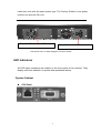
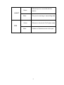
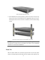
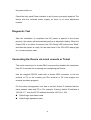
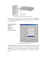
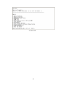
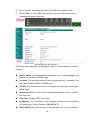
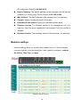
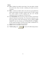
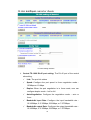
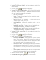
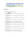
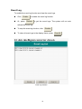
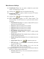
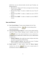
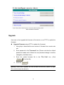
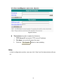
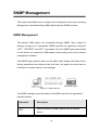
Raven Series Modular
Media Converter System
MIL-RCM16A-V2 16 Slot Raven Conversion Modules
Managed Chassis with AC Power Supply
USER GUIDE
Regulatory Approval
- FCC Class A
- UL 1950
- CSA C22.2 No. 950
- EN60950
- CE
- EN55022 Class A
- EN55024
Canadian EMI Notice
This Class A digital apparatus meets all the requirements of the Canadian Interference-Causing Equipment
Regulations.
Cet appareil numerique de la classe A respecte toutes les exigences du Reglement sur le materiel brouilleur du
Canada.
European Notice
Products with the CE Marking comply with both the EMC Directive (89/336/EEC) and the Low
Voltage Directive (73/23/EEC) issued by the Commission of the European Community
Compliance with these directives imply conformity to the following European Norms:
- EN55022 (CISPR 22) - Radio Frequency Interference
- EN61000-X - Electromagnetic Immunity
- EN60950 (IEC950) - Product Safety
One-Year Limited Warranty
Transition Networks warrants to the original consumer or purchaser that each of it's products,
and all components thereof, will be free from defects in material and/or workmanship for a
period of one year from the original factory shipment date. Any warranty hereunder is
extended to the original consumer or purchaser and is not assignable.
Transition Networks makes no express or implied warranties including, but not limited to, any
implied warranty of merchantability or fitness for a particular purpose, except as expressly set
forth in this warranty. In no event shall Transition Networks be liable for
incidental or consequential damages, costs, or expenses arising out of or
in connection with the performance of the product delivered hereunder
Transition Networks will in no case cover damages arising out of the
product being used in a negligent fashion or manner.
Trademarks
The MiLAN logo and Transition Networks trademarks are registered trademarks of Transition Networks in the
United States and/or other countries.
To Contact Transition Networks
For prompt response when calling for service information, have the following information ready:
- Product serial number and revision
- Date of purchase
- Vendor or place of purchase
You can reach Transition Networks technical support at:
E-mail: [email protected]
Transition Networks
10900 Red Circle Drive
Minnetonka, MN 55344
United States of America
Telephone: +1.800.526.9267
Fax: : +1.952.941.2322
http://www.milan.com
info@ Transition.com
© Copyright 2006
Transition Networks
FCC Warning
This Equipment has been tested and found to comply with the limits for a Class
A digital device, pursuant to Part 15 of the FCC rules. These limits are designed
to provide reasonable protection against harmful interference in a residential
installation.
This equipment generates, uses and can radiate radio frequency
energy and, if not installed and used in accordance with the instructions, may
cause harmful interference to radio communications.
no
guarantee
that
interference
will
not
However,
occur in a
there
is
particular
installation. If this equipment does cause harmful interference to radio or
television reception, which can be determined by turning the equipment off and
on, the user is encouraged to try to correct the interference by one or more of
the following measures:
Reorient or relocate the receiving antenna.
Increase the separation between the equipment and receiver.
Connect the equipment into an outlet on a circuit different from that to which the
receiver is connected.
Consult the dealer or an experienced radio/TV technician for help.
CE Mark Warning
This is a class A product. In a domestic environment this product may cause radio interference in
which case
the user may be required to take adequate measures.
Content
Content .................................................................................. 4
Introduction ........................................................................... 1
Features....................................................................................................1
Software Feature ......................................................................................2
Management Methods ..............................................................................4
Console and Telnet Management......................................................4
Web-based Management ..................................................................4
SNMP Network Management ............................................................4
Package Contents ....................................................................................5
Hardware Description ........................................................... 6
Physical Description .................................................................................6
Front & Rear Panel ...................................................................................6
LED Indicators ..........................................................................................7
System Cabinet .................................................................................7
Connecting to the Network................................................. 10
Pre-Installation Requirements.................................................................10
Mounting the Device ...............................................................................10
Desktop Installation .........................................................................11
Attaching Rubber Pads.............................................................11
Rack Mounting..........................................................................11
Power On................................................................................................12
Diagnostic Test .......................................................................................13
Connecting the Device via Local console or Telnet ................................13
Console Management ......................................................... 16
Device Setting.........................................................................................16
Modules Settings ....................................................................................18
Redundant Power Status ........................................................................20
Events Log..............................................................................................21
SNMP Trap .............................................................................................21
Secure IP for Telnet, HTTP and SNMP ..................................................22
Port Counters..........................................................................................23
Fan Status ..............................................................................................23
Save Current Settings.............................................................................24
Factory Default Settings & Reboot System.............................................24
Reboot System .......................................................................................25
TFTP Configuration ................................................................................25
Web-Based Management .................................................... 26
About Web-based Management .............................................................26
System Login ..........................................................................................27
Modules settings.....................................................................................29
Port Counter ...........................................................................................34
IP Config .................................................................................................35
SNMP .....................................................................................................36
Event Log................................................................................................37
Miscellaneous Settings ...........................................................................38
Save and Reboot ....................................................................................40
Upgrade ..................................................................................................41
Help ........................................................................................................42
SNMP Management ............................................................. 43
SNMP Management ...............................................................................43
Specification........................................................................ 45
Introduction
The 16 Slots intelligent converter chassis is a combination of 16-slot host
cabinet and several of optional media converter bracket modules. A maximum
16-bracket module can be installed in the cabinet with two redundant power
supplies. The Power supply supports AC input type with load sharing
redundant feature. The converter supports TS-1000 standard that provides
loop back test to ensure the converter failure and remote configuration that
allows remote set-up for the module of the converter or the converter.
With build-in Web-based Management, managing and configuring the 16 Slots
intelligent converter chassis becomes easier. Users can visually configure and
manage their network via the Web browser. Besides, the 16 Slots intelligent
converter chassis can also be managed via Telnet, Console, or third-party
SNMP Management.
Features
16 slots converter chassis with 2 power slots
AC power with Redundant
Maximum 16 slots for media converter
HTTP, Telnet security
IP address security for management station
Web and TFTP firmware upgrade
Built-in Link Lost Forwarding (LLF)/Link Fault Pass-Through (LFP)
Back-door password supported
Module identification
Fiber Module hot-swappable
CPU module hot-swappable
SNMP, Web, Telnet, console management
Optional different converter modules: 10/100TX to 100FX module,
1
100/1000TX to Gigabit fiber module, 100/1000TX to Mini-GBIC module,
and 100FX WDM module
100FX and Gigabit modules support single mode or multi mode fiber
Supports TS-1000 on 10/100TX to 100FX module and 100FX WDM
module
Event log and SNMP Trap supported
SNMP MIB II and private MIB supported
Supports Simple Network Time Protocol (SNTP)
Power and Fan Detect
Loop Back Test
EIA RS-310C 19 “ standard
Software Feature
Telnet
Management
Web
Console (RS-232)
Web/Telnet
MIBS
Web and Telnet function Can be enabled or
disabled
RFC 1213 MIB II
Private MIB
Link down
Link up
Power module status change
SNMP Trap
Authorization Fail
Module plug in and plug out
Chassis configuration change
Module configuration change
2
Software Upgrade
Firmware upgrade by Web interface and TFTP
Each module supports LLF feature. It can be set by
Web or CLI menu
Link Loose
LLF Mode TX → Fiber: TX port link down, the fiber
Forward
port will be forced down
LLF Mode Fiber → TX : Fiber port link down, the
TX port will be forced down
TX port: IN-good / In-bad packet counter
out-good /out-bad packet counter
Packet counter
collision counter
Fiber port: IN-good / In-bad packet counter
out-good /out-bad packet counter
SNMP Trap Node
Up to 4 Trap nodes
IP security for telnet
IP security
HTTP and SNMP access
Up to 4 IP nodes when security is enabled
TS-1000
Loop back test, remote configuration
SNTP
RFC2030 Simple Network Time Protocol
Events log
Up to 4095 event records. It can be reviewed by CLI
and Web browser mode
3
Management Methods
The 16 Slots intelligent converter chassis supports following management
methods:
Console and Telnet Management
Web-based Management
SNMP Network Management
Console and Telnet Management
Console Management is done through the RS-232 Console Port that requires a
direct connection between PC and the Device. Once the Device is on the
network, you can use Telnet program to Log in and modify the configuration.
The default IP address is 192.168.1.77 with a subnet mask of 255.255.255.0.
This default address can be used to login and change the configuration using
Telnet.
Web-based Management
The 16 Slots intelligent converter chassis provides an embedded HTML web
program in flash memory. It offers advanced management features and allows
users to manage the 16 Slots intelligent converter chassis from anywhere on
the network through any HTTP browser such as Microsoft Internet Explorer.
For more information, please see the section of Web-Based Management.
SNMP Network Management
SNMP (Simple Network Management Protocol) provides a way to monitor and
control network device, such as configurations, statistic collection, performance,
and security.
Data is collected by SNMP agents, which are hardware & software processes
reporting activity in each network device. The agent reports information
contained in a MIB format (Management Information Base), which is a data
structure that defines what is obtainable from the device and what can be
controlled.
4
Package Contents
Unpack the carton of the 16 Slots intelligent converter chassis and verify them
against the checklist below:
16 Slots intelligent converter chassis
Power Cord
Four Rubber Pads
RS-232 cable
User Manual
16 Slots intelligent converter chassis
RS-232 cable
Rubber Pads
User Manual
Rack-mounted Kit
Power Cord
Package Contents
Compare the contents of your 16 Slots intelligent converter chassis package
with the standard checklist above. If any item is missing or damaged, please
contact the local dealer for service.
5
Hardware Description
The 16 Slots intelligent converter chassis is a modular unit that contains 16
slots and 2 power slots. All optional models come with the built-in CPU, and the
RS-232 port is used for Out-of-Band Management and one Ethernet RJ-45
connector is for In-band management that both in front panel.
This section mainly describes the hardware of the 16 Slots intelligent converter
chassis and gives a physical and functional overview on certain module
converter.
Physical Description
The physical dimensions of the 16 Slots intelligent converter chassis is 448mm
x 279mm x 89mm (Lx W x H)
Front & Rear Panel
The front panel of 16 Slots intelligent converter chassis with the cabinet and
modules is shown as figure below:
Front Panel (within all modules)
The 3-pronged power plug is located at the Rear Panel of the 16 Slots
intelligent converter chassis as shown in Figure 2-2. The AC power is in the
range between 100 and 240VAC, 50-60Hz (AC type power supply). System can
6
install two units with the same power type. The Factory Default is one power
module unit and one Fan Unit.
Power Slot B is installed a FAN unit
Power Slot A with AC Power Module
Rear Panel of the 16 Slots intelligent converter chassis
LED Indicators
All LED status indicators are located on the front panel of the modules. They
display real-time indication of system and operational status.
System Cabinet
CPU Panel
7
LED
CPU
Ready
PWR
Status
Meaning
Blink
(Green)
System kernel is working correctly
Green
Power on
Green
Power Module A Ready
Off
Power Module A Not Ready
Green
Power Module B Ready
Off
Power Module B Not Ready
Orange
Power Module A Fail
Off
Power Module A Ready
Orange
Power Module B Fail
Off
Power Module B Ready
Good A
Good B
Fail A
Fail B
8
Ethernet port is connected with the
Green
device.
LK/ACT
Blink
The port is receiving or transmitting data
Yellow
Ethernet is linked with Full Duplex mode
Blink
Collision of Packets occurs in the port.
FDX
Descriptions of the System and CPU LED
9
Connecting to the Network
This chapter provides the installation procedure.
Pre-Installation Requirements
Before to start hardware installation, make sure the installation environment
has following items:
PCs with 10/100Base-TX Ethernet cards: The PC must have a standard
Ethernet interface to connect with the Device.
UTP/STP cable with RJ-45 connector: Check the cable and connectors
work properly.
Fiber cable with SC/ST/MT-RJ/VF-45 connector: Check the cable and
connector types are correct.
A power outlet: 100 to 240V AC at 50 to 60 Hz. Make sure that the
Device power is accessible and cables can be connected easily.
Dedicated power supply: Use dedicated power circuits or power
conditioners to supply reliable electrical power to the network devices.
A dry cool place: Keep the device away from moisture. Avoid direct
sunlight, heat source, and high amount of electromagnetic interference
around.
Mounting tools: If user intends to mount the device on a rack, make sure
have all the tools, such as mounting brackets and screws.
Mounting the Device
The 16 Slots intelligent converter chassis is suitable for an office environment
where it can be rack-mounted in standard EIA 19-inch racks or standalone.
10
Desktop Installation
Set the device on a sufficiently large flat space with a power outlet nearby. And,
the surface where user put the device should be clean, smooth, level, and
sturdy. Please make sure there is enough spacing around the device to allow
attaching of cables, power cord and air circulation.
Attaching Rubber Pads
1. Make sure mounting surface on the bottom of the device is grease and dust
free
2. Remove adhesive backing from Rubber Pads
3. Apply the Rubber Pads to each corner on the bottom of the device. (These
footpads can prevent the device from shock/vibration.)
Attaching Rubber Pads to each corner of the Device’s bottom
Rack Mounting
The 16 Slots intelligent converter chassis come with a rack-mounted kit and
can be mounted in an EIA standard size/19-inch Rack. Perform the following
steps for rack mounting the device:
1. Position one bracket to align with the holes on the side of the device and
secure it with the bracket screws. Then attach the remaining bracket to the
other side of the Device.
11
Attach mounting brackets with screws
2. After attached both mounting brackets, position the device in the rack by
lining up the holes in the brackets with the appropriate holes on the rack.
Securing the device to the rack with a screwdriver and the rack-mounting
screws.
Mount the converter chassis in an EIA standard 19-inch Rack
[NOTE] For proper ventilation, allow at least 4 inches (10 cm) of clearance on
the front and 3.4 inches (8 cm) on the back of the Device. This is especially
important for enclosed rack installations.
Power On
After all network cables are connected, plug the power cord into the power
socket on the back panel and the other end into a power outlet, and then turn
12
the power switch on.
Check the front panel Power indicator to see if power is properly supplied. The
device with the universal power supply, so there is no more adjustment
needed.
Diagnostic Test
After the installation is completed and AC power is applied to the device
properly, the system will automatically perform a diagnostic testing. When the
Power LED is on within 4 seconds, the CPU Ready LED will become “Blink”
and then the system is ready. On the other hand, if the CPU LED always light
on, it means system crash.
Connecting the Device via Local console or Telnet
The serial console port is a male DB-9 connector that enables the connection
from PC or terminal for monitoring and configuring the Device.
Use the supplied RS-232 cable with a female DB-9 connector to link the
terminal or PC to the console port.(The terminal or PC must support the
terminal emulation program)
For the telnet management, user has to set the device IP address that the
same network class with PC’s. (For example; it factory default IP address is
192.168.1.77, then the PC IP address should be 192.168.1.156)
Default login user name: root
Default login password: root
13
Connecting the Device to a terminal via RS-232 cable
After connected to the Console port, turn the PC or terminal on and configure
its communications parameters to match the following default characteristics
of the console port:
Baud Rate: 9600 bps
Data Bits: 8
Stop Bit: 1
Parity: none
Flow control: None
The setting of communication parameters
Run Hyper Terminal or a terminal emulation program using the above settings
for Console Management. After user has finished parameter settings, press
Enter and key the login username and password. The default login username
and password both is “root”. After authentication, enter “m” to enter main
menu.
14
The Main Menu
15
Console Management
In this chapter, console management will be described individual function. In
fact, console management mode is a line menu mode. User can enter the
number of function to configure the function.
Device Setting
Select Device settings (Type “1” and press “Enter”) from the main menu. It
displays the list of device settings items, ex: system name, location, IP… and
so on. User can enter the number to modify the value.
Device Settings interface
[NOTE] The item “0.1, 0.2, 0.3” can’t be modified.
1. Device Name: Set a system name for this device (Character maximum
length is 64)
2. Location:
the description for the location of device(Character
maximum length is 64)
16
3. Contact: the description for the contact people of device(Character
maximum length is 64)
4. IP Address: The IP address of the device(The default IP is
192.168.16.77)
5. Subnet Mask: The default value is 255.255.255.0
6. Default Gateway: The default value is 192.168.16.254
7. Change User/Password: User can change to other username or
password (The default username and password is root)
8. Get Request Community: The community string for get(The default
value is Public)
9. Set Request Community: The community string for set(The default
value is “Public)
A. HTTP Enable: To allow user to configure the converter through Web
B. Telnet Enable: To allow user to remote telnet to the converter for
configuring
C. Set SNTP Config: Configuring the SNTP (Simple Network Time
Protocol) settings. The SNTP allows user to synchronize switch clocks in
the Internet
1. Enable/Disable Sntp Client: To enable or disable SNTP function
to get the time from the SNTP server
2. Set Sntp Server 1 Ip: Set the SNTP server IP address
3. Set Sntp Server 2 Ip: Set the SNTP server IP address
4. Set Sntp Server 3 Ip: Set the SNTP server IP address
5. Set UTC Timezone: Set the switch location time zone
7. Enable/Disable Daylight Saving: To enable or disable daylight
saving function
8. Set Daylight Saving Period: When daylight saving is enabling,
user can set up the daylight saving period
9. Set Daylight Saving Offset: Set up the daylight saving time offset
value.
A. Enable/Disable Auto Sync to SNTP server: Automatically
synchronize time with the SNTP server
B. Set Auto Sync period: Set up the time that automatically
synchronizes time with SNTP server
17
Q. Quit: Exit from the current configuration interface
Remember to return the Main Menu to Save the modified settings, and then
reboot the device. User may have to press Enter again when the device is
finished reboot.
Modules Settings
Configure the operation mode of the media converter modules.
Input “2” and press “Enter “at main menu interface. The system will guide the
user to select the module for configuration (Enter the number of module, ex: ‘1’
and then press “Enter”).
After entering the module configuration mode, the module configuration
interface will list the items as shown in the figure below. Selections 1 ~ 7 allow
users to configure the module settings. The items of 0.1 ~ 0.5 are read-only
information. Enter the number of selection to modify the value.
18
Module setting interface (support TS-1000 module)
1. Module enable/disable: Enable or disable module function (The
default is “Enable”).
2. LLF enable/disable: When the RJ-45 or Fiber is link down, it will force
the other port disconnect automatically. The forced way is depends on the
RJ-45 control Fiber or Fiber control RJ-45 port. The LLF default is “RJ-45
Control FX” and other selections are “Fx Control RJ-45” and “Disable”.
On the module that support TS-1000 only can enable or disable the LLF
function but can not configure the LLF direction
3. RJ-45 Port Speed/ Duplex: Configuring RJ-45 port speed and
mode.(The default is “10M/Half”)
4. Fiber Port Speed/Duplex: Configuring Fiber port speed and mode(The
default is “10M/Half”)
5. Reset to default: To reset the module configuration to default value
6. Note: Entering the short description or note for this module
7. TS-1000 Setting: It is used for configuring the TS-1000 functions. Only
the module supporting TS-1000 standard has this configuration item.
1. Embedded SSRAM BIST: To test central site converter module
status. When test back value is OK which means the central site
converter module is normal. When test back value is fail or didn’t test,
it means the central site converter module is fail
2. Power off Alarm (POA): To enable or disable the power off alarm
19
function. Enable means before the remote converter power off, the
remote converter will send out the alarm notice to the central manager
converter
3. In-Band Loop Back Test: Checking the fiber port connection
status between remote and central site converter. User needs to set a
transfer value, and verify the return value is for verifying if the value
the same as user has set
4. Auto Loop Back Test: Checking the fiber port connection status
between remote and central site converter automatically
5. Bandwidth rate control & Terminal Tx port Config: Bandwidth
rate control terminal UTP port
6. Terminal Tx port Table (Read only): Displaying the terminal UTP
port table information
8. Auto Polling: Set the value as ‘True’ to enable auto polling. When Auto
Polling is set as ‘True’, the management board then is able to
communicate with the particular module.
Q. Quit: Exit from the current interface
Redundant Power Status
It shows current power supply status. The device has two slots for Power
20
module, on the left is power A, and on the right is power B. In main menu
interface, enter “3” and press enter. Then, user will see as the following figure.
Redundant Power Status interface
Events Log
The system provides 4095 event records
1. Event Log Enabled: The System will start record events when it is
“enable”
2. Show Event Log: For viewing event log records. To enable “Event Log
Enable” function
3. Delete All Event Log: Removing all event log entries which are stored
in system Flash Rom
Q. Quit: Exit from the current interface
Event Log interface
SNMP Trap
Configure SNMP Trap station. User can configure up to 4 IP address for trap.
1. Send Trap: To enable or Disable Trap function
21
2. Trap community: The Trap station must have same community string
and can get trap information from this device(The maximum trap
community string length is 32 characters. The default community string is
“public”)
3~4. Trap IP 1~4: Assign the trap station’s IP address. Only the
authorized station can receive the Trap information
Q. Quit: Exit from the current interface
SNMP Trap interface
Secure IP for Telnet, HTTP and SNMP
Configuring security management for Telnet, Web management and
SNMP( four would be the maximum number of stations), If the function is
enabled, then only the authorized station that with right IP address can manage
this device.
Secure IP interface
1. Secure IP for Telnet: To Enable or disable the secure Telnet IP
22
function
2. Secure IP for HTTP: To Enable or disable the secure HTTP IP function
3. Secure IP for SNMP: To Enable or disable the secure SNMP IP
function
4~7. Secure IP 1~4: Assigning the IP that can manage the device through
Telnet, HTTP and SNMP
Q. Quit: Exit from the current interface
Port Counters
Viewing UTP and fiber port counter information
1. RJ-45: Viewing all the UTP port counter information
2. Fiber: Viewing all fiber port counter information
3. Reset: Reseting all port counters
Q. Quit: Exit from the current interface
Port Counters interface
Fan Status
For newest Fan status viewing, press “enter” key to bring it up
Fan Status interface
23
Save Current Settings
After modifying, the parameters still not save in the system. User need to do
the save action, then all the parameters will be stored in system Flash Rom.
The values will be effect after reboot. Enter “R” and press “Enter” key to save
the current settings.
Save Current Settings interface
Factory Default Settings & Reboot System
To reset the system configuration back to original settings. After reboot, the
system configuration will set to default value. Enter “D” and press “Enter” key.
There are three optional selections that user can decide to set back to default
value or keep current value.
Module settings: User might keep current configure value when the
system set to factory default settings. Enter “n” the current configure value
will remain after the system set to factory default. Enter “y” the current
configure value will be set to the factory default setting.
IP settings: User might keep current IP address when the system set to
factory default settings. Enter “n” the current IP address will remain after
the system set to factory default. Enter “y” the current IP address will be
set to the factory default setting.
Factory default settings & Reboot system interface
24
Reboot System
To reboot the system without set the system configuration back to default.
Enter “R” and press “Enter” key.
TFTP Configuration
Use TFTP function to update the firmware
1. Set TFTP Server IP: set up the TFTP server IP address
2. Set File Name: set up the firmware file name
3. Update Firmware: execute the TFTP update firmware
Q. Quit: exit from the current interface
TFTP Configuration interface
25
Web-Based Management
About Web-based Management
The 16 Slots intelligent converter chassis support embedded HTML web
manage. It offers advanced management features and allows users to manage
the device from anywhere on the network through a standard browser such as
Microsoft Internet Explorer.
The Web-Based Management supports Internet Explorer 5.0. And, it is applied
with Java Applets for reducing network bandwidth consumption, enhance
access speed and present an easy viewing screen.
[NOTE] By default, IE5.0 or later version does not allow Java Applets to
activate sockets. In fact, the user has to explicitly modify the browser setting to
enable Java Applets to operate network ports.
The user has to download the Java Run Time Environment application to
enable Java Applets. Please go to http://java.sun.com/products/archive/, select
the JDK/JRE Version 6 update 7.
[NOTE] The Web-Based Management support only JDK/JRE Version 6
update 7, there is no commitment on the compatibility of other Java
environment
26
JDK/JRE download page
System Login
Follow the step below to login system
1.
Start Internet Explorer
2.
Key in” http://” + “the IP address of the 16 Slots intelligent converter
chassis” (for example, the Factory default is 192.168.16.77) and press
“Enter” key.
The authentication Window
3.
The authentication screen appears
27
4.
Key in the user name and password. The default is “root” for both
5.
Press “Enter” or Click ”OK”, then the Home Screen of the Web-based
management appear right after
Web management Home interface
The Home page displays the configuration of the 16 Slots intelligent converter
chassis.
Device Name: An administratively assigned name of the managed unit
that can be modified in SNMP page
Location: The physical location of this managed unit (e.g., laboratory, 3rd
floor) that can be modified in SNMP page
Contact: The contact person for this managed unit that can be modified in
SNMP page
System Up Time: The time last since the managed unit was re- initialized.
It is read only
Sntp Time: Display SNTP time status
IP Address: The IP address of the managed unit that can be modified in
IP Config page. Factory Default is 192.168.16.77
Subnet Mask: The subnet mask of the managed unit can be modified in
28
IP Config page. Default is 255.255.255.0
Default Gateway: The default gateway of the managed unit that can be
modified in IP Config page. Factory Default is 192.168.16.254.
MAC Address: The MAC address of the managed unit. It is read only
Console: display console parameter information
Redundant Power status: Display the redundant power status
Firmware Version: The firmware version of the management unit. It is
read only. User can online upgrade the new firmware if the new version is
released
Hardware Version: The hardware version of the converter. It is read only
Modules settings
Modules settings show the modules that installed on the 16 Slots intelligent
converter chassis. In modules settings, it has 4 parts for configure—module,
RJ-45 Port, Fiber Port, and Note.
Modules Settings interface
29
Module
State: It displays the module current status. User can enable or disable
the module state. When the state is disabling, this module cannot be
configured
Mode: It shows the module mode. The mode was auto detected by
system when installed on the device. When the mode is TS-1000, it means
this module supports TS-1000 standard and then click TS-1000
configuration button to configure the TS-1000 function
LLF enable/disable: When the RJ-45 or Fiber is link down, it will force the
other port disconnect automatically. The forced way is depends on the
RJ-45 control Fiber or Fiber control RJ-45 port. The LLF default is “RJ-45
Control FX” and other selections are “Fx Control RJ-45” and “Disable”.
On the module that support TS-1000 only can enable or disable the LLF
function but can not configure the LLF direction
Default: set the module back to default value
TS-1000 setting: click
config #
to enter the TS-1000 setting interface
30
TS-1000 setting interface
Central TS-1000 RJ-45 port setting: The RJ-45 port of the central
site setting.
Link: The port link status
Speed: Configure the port speed in force negotiation mode –
100Mbps or 10 Mbps
Duplex: When the port negotiation is in force mode, user can
configure duplex mode – half or full
Auto-Negotiation: Configure the negotiation mode – auto or
force
Bandwidth Input Rate: Configure the input bandwidth rate –
10/100Mbps, 2.5/ 25Mbps, 5/50Mbps, or 7.5/75Mbps
Bandwidth output Rate: Configure the output bandwidth rate –
10/100Mbps, 2.5/ 25Mbps, 5/50Mbps, or 7.5/75Mbps.
31
Central TS-1000 reset default: Set the configuration back to the
default settings
And then, click
Terminal TS-1000 RJ-45 port setting: The RJ-45 port of the terminal
Apply
to apply the configuration
site setting. When the connection is established between the central
site, user are able to configure the terminal site
Link: the port link status
Speed: Configure the port speed in force negotiation mode –
100Mbps or 10 Mbps
Duplex: When the port negotiation is in force mode, you can
configure duplex mode – half or full
Auto-Negotiation: Configure the negotiation mode – auto or
force
Bandwidth Input Rate: Configure the input bandwidth rate –
10/100Mbps, 2.5/ 25Mbps, 5/50Mbps, or 7.5/75Mbps
Bandwidth output Rate: Configure the output bandwidth rate –
10/100Mbps, 2.5/ 25Mbps, 5/50Mbps, or 7.5/75Mbps
Terminal TS-1000 reset default: Set the configuration back to the
default settings
And then, click
Verify Test: Set up some TS-1000 loop back test
Apply
to apply the configuration
Embedded SSRAM BIST: To test central site converter module
status. When test back value is OK, it means the central site
converter module is normal. When test back value is fail or didn’t
test, it means the central site converter module is fail
In-Band Loop Back Test: Checking the fiber port connection
status between remote and central site converter. User needs to
set a transfer value and verify the return value same as user has
set
Auto Loop Back Test: Checking the fiber port connection status
between remote and central site converter automatically
When all items are set, click
TS-1000 POA setting: Set up the power off alarm function
Test
32
to start the testing
Power off Alarm (POA): To enable or disable the power off
alarm function. Enable -- before the remote converter power off,
the remote converter will send out the alarm notice to the central
manager converter
And then, click
Apply
to apply the configuration
RJ-45 Port
Link: Showing the RJ-45 port current link status
Nego: Select the negotiation mode
Auto means the system automatically select the speed(Default)
Force means the user can select the speed
Speed: Select the speed of port (Make sure the “Nego” column is set as
“Force”; Otherwise, the speed function will be disable)
Duplex: Select the Duplex mode. (Make sure the “Nego” column is
“Force”; Otherwise, the duplex function is disabling)
Fiber Port
Link: It shows the RJ-45 port current link status
Nego: Select the negotiation mode
Speed: Select the speed of port
Duplex: Select the Duplex mode
Note: A note can be filled in for this module within maximum characters is
32
After modifying, click
Apply
to have the configuration taken effect.
33
Port Counter
Display all port counter information in here
Click
Rx Good Pkts(R): Amount of good packets has received/R means RJ-45
Refresh
to get current information
port
Rx Bad Pkts(R): Amount of good packets has received/R means RJ-45
port
Tx Good Pkts(R): Amount of good packets has transmitted/R means
RJ-45 port
Tx Bad Pkts(R): Amount of bad packet has transmitted/R means RJ-45
port
Tx Collision (R): Amount of transmit collision/R means RJ-45 port
Rx Collision (R): Amount of receive collision/R means RJ-45 port
Rx Good Pkts(F): Amount of good packets has received/F means Fiber
port
Rx Bad Pkts(F): Amount of good packets has received/F means Fiber
port
Tx Good Pkts(F): Amount of good packets has transmitted/F means Fiber
port
Tx Bad Pkts(F): Amount of bad packet has transmitted/F means Fiber
port
Tx Collision (F): Amount of transmit collision/F means Fiber port
Rx Collision (F): Amount of receive collision/F means Fiber port
34
Port Counter interface
IP Config
Changing of the IP address, subnet mask, and default gateway. Just simply fill
in the new IP address, subnet or default gateway in corresponding column.
Then, click
Apply
to have the configuration taken effect. Users should
reboot system to restore the new settings.
IP Config interface
35
SNMP
Configuring device name, location, contact, the "get request", "set request" and
Trap community string. The default value of get request, set request and Trap
community is “public”. These three parameters must be correctly to performed
"get request" from the management unit, "set request" to the management unit
and send trap to the management unit, then click
Apply
to have the
settings taken effect. There are up to 4-trap management stations could set to
receive the trap packets from the 16-slot chassis converter. Check marks the
“send traps to the following management stations” and fill in the IP address
of trap management station. Remember to set the Trap community while
send and receive trap packet between the converters and trap management
stations. The trap community must be same between the converters and trap
management station. At last, click
Apply
effect.
SNMP interface
36
to have the configuration taken
Event Log
To enable the event log function and view the event logs
Click
Or, press
Enable
to enable the event log function
Refresh
to get the event logs. The system will not auto
refresh the event log
To stop the event log function, click
To clear all event logs in the display frame, press Clear All
Disable
Event Log interface
37
Miscellaneous Settings
Enable/Disable Telnet: User can enable or disable the remote telnet
function. The default value is “enable”
And then, click
Enable/Disable HTTP: To enable or disable the remote HTTP function.
Apply
to have the configuration taken effect
The default value is “enable”
And then, Click
SNTP Configuration: Configure the SNTP (Simple Network Time
Apply
to have the configuration taken effect.
Protocol) settings. The SNTP allows user to synchronize switch clocks in
the Internet.
Enable/Disable Sntp Client: To enable or disable SNTP function to
get the time from the SNTP server
Sntp Server 1 IP: Set the SNTP server IP address
Sntp Server 2 IP: Set the SNTP server IP address
Sntp Server 3 IP: Set the SNTP server IP address
UTC Timezone: Set the switch location time zone
Enable/Disable Daylight Saving: To enable or disable daylight
saving function
Daylight Saving Period: When daylight saving is enabling, you can
set up the daylight saving period
Daylight Saving Offset (minutes): Set up the daylight saving time
offset value
Update System Time: click
SNTP auto sync: To enable or disable automatically synchronize
Apply
to update the system time
time with the SNTP server
SNTP auto sync period (minutes): Set up the time that
automatically synchronizes time with SNTP server
Change Password: Re-set the login username and password. Mark the
check box to enable password change setting
Username (max 15): Key in the new username(The maximum of
length is 15 characters)
38
Password (max 15): Key in the new password(The maximum of
length is 15 characters)
Confirm Password: Re-enter the new password for confirmation
Misc Settings Interface
Security IP: Configure security management for Telnet, Web management
and SNMP, and the maximum number of stations are 4, if the function is
39
enabled then only the authorized station that with right IP address can
manage this device.
Secure IP 1~4: Assign the IP that can manage the device through
Telnet, HTTP and SNMP
Secure IP for Telnet: To enable or disable the secure Telnet IP
function
Secure IP for HTTP: To enable or disable the secure HTTP IP
function
Secure IP for SNMP: To enable or disable the secure SNMP IP
function
Save and Reboot
Save Current Settings: To save current settings by click the "Save
Current Settings" and click the
Apply , then current settings will be
executed automatically
Factory Default Settings & Reboot: To use the factory default settings,
check the "Factory Default Settings& reboot" checkbox then click
the Apply . There are two optional selections for user to choose from,
which are restoring modules back to default value or just IP address back
to default value
Default all Modules: User might keep current configure value when
the system is set as factory default settings
Reset to default IP address: User might keep current IP address
when the system is set as factory default settings
Reboot system: To reboot system, check the "Reboot System"
checkbox then click the
Apply . Please wait a moment (about 15
seconds) then continue to operate the device
40
Save and Reboot interface
Upgrade
User can on-line upgrade the firmware of the device or use TFTP to update the
firmware
Upgrade Firmware(using HTTP to update the firmware)
1.
Using http to download the new version of firmware from vendor web
site
2.
Enter password in the "Password" box (Please note that the default
password is root, and it follows the user password change it could be
changed by individual user.)
3.
Enter the update firmware file in the "File Path" box. (Click
Browse
4.
to find the file)
Click the Upgrade
[NOTE] If users can't upgrade the new firmware successfully, please try again
(Do not shut down the device!)
41
Upgrade interface
Tftp Update(using tftp to update the firmware)
1.
TFTP Server IP: set up the TFTP server IP address
2.
File Name: set up the firmware file name
3.
Click the Tftp Upgrade
button to start updating.
Help
In each configuration section, user can click “Help” and the help window will pop
up.
42
SNMP Management
This section describes how to configure and manage the device by accessing
Management Information Base (MIB) objects with the SNMP protocol.
SNMP Management
The device’s MIB options are accessible through SNMP. Also, instead of
defining a large set of commands, SNMP performs all operations using the
“GET”, “GETNEXT” and “SET” commands. And, the SNMP agent that resides
on the device can respond to MIB-related queries being sent by the network
management software.
The SNMP agent gathers data from the MIB, which keeps information about
device parameters and network data. And then, the agent can send traps or
notification of certain events to the manager.
Figure 6-1 SNMP Network
The SNMP manager uses information in the MIB to perform the operations
described below:
Operation
GET
Description
Retrieve values of SNMP objects from a network
device
43
Specify an SNMP object in a network device and then
GETNEXT
retrieve information about the rest of SNMP objects in
the device
SET
Modify and store values of SNMP objects in a network
device
GET
Replying the GET, GETNEXT, and SET commands are
RESPONSE
sent by SNMP agent
TRAP
A message sent by an SNMP agent to an SNMP
manager indicating some event occurred
The commands of SNMP management
44
Specification
This section provides the specifications of the converter modules
IEEE802.3 10BASE-T
IEEE802.3u 100BASE-TX and 100BASE-FX with
Standards
N-way auto negotiation
IEEE802.3ab Gigabit copper with N-way
auto-negotiation
IEEE802.3z for Gigabit fiber
100FX Module:
Fiber: Duplex ST/SC, Simplex SC (WDM
single mode)
RJ-45: CAT-5 (10/100Mbps) Twisted Pair
cable
Gigabit Module:
Fiber: Duplex SC (Single mode 10KM, Multi
mode 500Meters)
RJ-45 : CAT- 5 (1000Mbps) 4 pairs of
Connector
UTP/STP cable
CPU Board: RJ-45 for 10/100Mbps, Full/Half
Duplex. Cable support CAT-3/5
(10/100Mbps)
WDM module:
Fiber: Simplex SC (single mode 20KM)
RJ-45: CAT. 5 2 pairs of UTP cable
Mini GBIC module: (for 3.3v only)
Fiber: SFP module (empty)
RJ-45: CAT- 5 (1000Mbps) 4 pairs of UTP/STP
cable
Switch architecture
Store and Forward
45
Internal Packet Gap 960ns
Filter illegal
Error packet
CPU Module
CPU Ready, Power Good (A, B) Power Fail
(A, B), TX (link/Act, FDX)
100FX Module
Power, TX (Link /Act, speed, FDX), FX (Link
/Act, FDX)
LED Indicators
Gigabit Module
Power, Gigabit Copper (Speed, 1000Mbps,
LK/ACT, FDX/COL), Fiber (Link/Act,
FDX/COL)
100/1000TX to MINI GBIC module
Power, Gigabit Copper (Speed, 1000Mbps,
LK/ACT, FDX/COL), Fiber (Link/Act,
FDX/COL)
Fiber parameters
Fiber Core:
Multi-Mode (62.5/125um, 50/125um)
Single-Mode (9/125µm)
Wavelength:
100Mbps multi-mode: 1310nm / 100Mbps
single-mode: 1310nm
100M WDM 1310: TX 1310nm, RX 1550 nm
100M WDM 1550: TX 1550nm, RX 1310 nm
Available Fiber distance:
100Mbps module: Single-Mode Fiber (30 KM)
/ Multi-Mode (2KM)
100M WDM module (W13, W15): 20KM
Gigabit modules: SX (Multi-mode) 500 Meters
LX (Single mode) 10 KM
Optical Transceiver parameter:
46
100Mbps Multi-Mode: TX (–19dBm), RX
(-31dBm), Power budget (12dBm)
100Mbps Single-mode (30KM): TX (–15
dBm), RX (-34 dBm), Power budget (19dBm)
Gigabit SX Transceiver: TX (–9.5dBm), RX
(12.5 dBm), Power budget (3dBm)
Gigabit LX Transceiver: TX (–9.5dBm), RX
(-20 dBm), Power budget (10.5dBm)
64 to 1518 Bytes for Non-VLAN Ethernet packet
Transparent packet
68 to 1522 Bytes for VLAN-Tag type Ethernet
packet
Dimensions
Operational
Temperature
Transparent packet
448mmx 279mm x 89mm (W x D x H)
0ºC to 45ºC (32ºF to 113ºF)
64 to 1518 Bytes for Non-VLAN Ethernet packet
68 to 1522 Bytes for VLAN-Tag type Ethernet
packet
Power Supply
EMI & Safety
Redundant and Load Sharing function support (
AC: 90~240 VAC, 50/60 HZ
FCC Class A
/
CE / UL
10900 Red Circle Drive
Minnetonka, MN 55344
Tel.: +1.952.941.7600
[email protected]
47