1
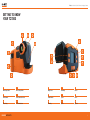
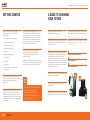
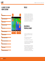
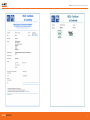
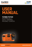
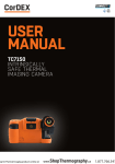
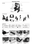
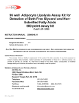
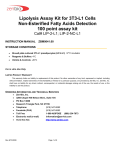
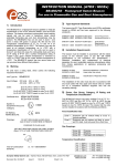
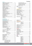
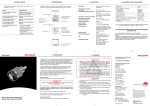
USER
MANUAL
TC7000
INTRINSICALLY
SAFE THERMAL
IMAGING CAMERA
RUGGED AUTHORITY
www.cord-ex.com
Congratulations – You are
the owner of the first fully
radiometric thermal imaging
camera designed and certified
specifically for use in hazardous
(explosive) atmospheres.
TC7000 is certified ATEX/IECEx as follows:
•
•
•
Ex ib IIC T4 Tamb -10ºC to +40ºC (Vapour)
Ex ib IIIC T200ºC Db Tamb -10ºC to +40ºC (Dust)
Ex ib I Mb (Mining)
!
Please ensure that the
certification matches or
exceeds the hazardous area
characteristics that will be
clearly displayed on site.
!
Whilst in a hazardous area, do
not attempt to change batteries
or download images, these
tasks should only be undertaken
after returning to a safe area.
CONTENTS
Getting To Know Your TC7000
4
Getting Started
6
A Guide To Charging Your TC7000
7
A Guide To Your Home Screen
8
Focus
9
Creating A Thermal Image
9
Menu Selection
11
RFID
12
Analysis
13
Settings
14
Parameters
15
Level/Span
16
Storing And Analysing Images
17
Technical Information
18
Certification
19
Ten Suggestions For Thermography Best Practice
22
T7000 – Intrinsically Safe Thermal Imaging Camera
GETTING TO KNOW
YOUR TC7000
2
1
3
1
1
6
9
4
7
5
8
6
4
2
5
1
Neck Strap Points
2
RFID Scanner
3
Focus Ring
Focus Ring
RUGGED AUTHORITY
4
1
Wrist Strap Points
5
Image Save
2
USB Connection Point
6
Power Switch
3
135˚ Swivel Lens
View Key
4
Menu Key
5
Span +
6
Span -
3
4
7
Level +
8
Level 9
Joystick
135˚ Swivel Lens
5
T7000 – Intrinsically Safe Thermal Imaging Camera
GETTING STARTED
A GUIDE TO CHARGING
YOUR TC7000
1
4
1
7
Check the contents of your TC7000.
The shipping case should include the
following items:
For comparative thermography, do not
amend the emissivity setting and leave this
constant every time you carry out imaging.
Temperature differences over time will then
be valid although the ambient temperature
may have changed as well as the electrical
or mechanical load of the object.
Remove the battery from the battery
compartment of the camera.
Insert the battery pack into the camera paying
careful attention to the orientation of the pack.
2
8
Plug the mains charging unit to a mains circuit
and plug the jack from the charging unit into
the battery station.
Remove battery when the camera is no longer
in use. DO NOT REMOVE BATTERY WHILST IN
HAZARDOUS AREA.
• TC7000 Thermal Imaging Camera
• USB Communication Wand
• USD Documentation Key
• Certificate of Conformity
• Neck Strap
• Rechargeable Battery Pack
• Lens Cleaner
• Wrist Strap
• Access key
5
3
For accurate thermal measurement the
emissivity of the object will need to be
considered and the camera emissivity
setting corrected.
In addition background and reflected ambient
will need to be considered as well as thermal
and solar reflection and relative humidity.
• Battery Charging Station and Mains
Charging unit
3
Before using TC7000 consider the objects
that you are going to image. Will you use
comparative thermography (simply looking
for temperature difference) or are you going
to attempt to make an accurate temperature
measurement?
RUGGED AUTHORITY
1
Rechargeable/Removable Battery
2
Mains Charging Unit
3
Battery Charging Station
4
2
Please ensure that you fully charge the
battery prior to use. The battery is charged
using the docking station supplied.
(See page 7.)
Insert the battery into the battery charging
compartment on the battery charging station.
A green light will show that the unit has
power. The charging light on the charging unit
will flash amber whilst the charger assesses
the charge held on the battery. Following this
a solid amber light will be displayed showing
that the unit is charging.
When the amber light is no longer displayed,
the battery is fully charged.
!
Please Note: It is recommended
that users attend formal
thermography training to
understand the implication of
these parameters.
5
2
1
Remove the battery from the charging
compartment.
6
Insert the battery pack into the camera paying
careful attention to the orientation of the pack.
3
7
T7000 – Intrinsically Safe Thermal Imaging Camera
A GUIDE TO YOUR
HOME SCREEN
FOCUS
1
4
1
RFID Tag Status Bar
2
Temperature Reading Spot #1
2
3
Temperature Spot #1
3
5
4
Maximum Image Temerature
CREATING A
THERMAL IMAGE
6
5
Temperature Scale
6
Minimum Image Temperature
7
Battery Charge Indicator
8
Ambient Temperature Selected
9
Reference Temperature Selected
10
Relative Humidity Selected
11
Emissivity Selected
12
IW Transmission Correction Icon
RUGGED AUTHORITY
12
11
10
9
• Correct focus is critical in producing an
effective thermal image. Slowly rotate the
knurled orange Focus Ring on the front of
the lens until the object is clearly in view.
You may find that the best focus is easier
to achieve using a grey scale palette. Make
sure that you focus on the object to be
measured rather than the background.
8
7
• Switch on the TC7000 by pressing and
holding the power switch for at least 3
seconds.
• Ensure auto Level/Span is enabled.
(See Settings section on P.13)
• Ensure that camera is correctly focused.
• You should now see a high quality thermal
image and be able to discern small spatial
and temperature differences.
• Spots (crosshairs) can be moved by using
the joystick. The temperature at that point
is displayed on the top left of the display.
When the crosshair is highlighted, pressing
and holding the joystick will allow the
emissivity of that spot only to be changed.
9
T7000 – Intrinsically Safe Thermal Imaging Camera
MENU SELECTION
• Pressing the joystick again will highlight
each spot in turn. This is followed by the
option for the TC7000 to scan for an RFID
tag. Place the top front of the camera within
5 cm of an RFID tag and press/hold the
joystick again. The RFID tag information
will be displayed and can be edited. (See
detailed RFID Section on P.11)
• All other camera settings and features are
selected through the menu button. Press this
once to display 6 icons.
• The settings icon enables the user to select
or deselect all of the display settings. (See
detailed Settings section on P.13)
• When the NUC icon is highlighted one press
of the joystick will perform a manual Non
Uniformity Correction (NUC). This should
not be required in normal use as the NUC
is carried out automatically when required.
A distinct click will be heard when the
NUC is performed and the thermal image
will be refreshed. A manual NUC may be
required when moving to different ambient
temperatures but very frequent NUC
operation will seriously impact battery life.
• The parameters icon allows all the
measurement parameters of the
thermal image to be altered to increase
temperature measurement accuracy. These
include emissivity, ambient temperature,
atmospheric temperature, relative
humidity and target distance. (See detailed
parameters section on P.14)
• When the analysis icon is highlighted
moving the joystick down will cycle through
crosshair (spot) selection (0,1,2 or 3),
maximum temperature display (within entire
image), minimum temperature display (within
entire image). (See detailed analysis section
on P.12)
RUGGED AUTHORITY
• The clock icon enables setting of all time
and date information.
• The info icon displays camera serial number,
internal memory used, remaining internal
memory and battery capacity.
11
T7000 – Intrinsically Safe Thermal Imaging Camera
RFID
ANALYSIS
• When an RFID tag is located an RFID details
menu will be displayed which shows the
hexadecimal identification of the RFID tag.
There are three settings in the analysis menu:
• It is recommended that an alias is then
added for future identification the tag
location . Use the joystick to highlight the
alias section (complete with selecting OK)
and then input a simple description through
the qwerty options (complete with selecting
OK - this can be edited later in CorDEX
CONNECT)
The No. spots icon allows choice of 0, 1, 2 or
3 temperature spots (crosshairs) within the
display that will update in real time
• Select whether the RFID Tag is built into
a CorDEX IR window (IW2000, IW3000,
IW4000) or if it is a stand alone tag (NON
CDX).
• With the RFID tag editing complete select
SAVE to store this information for future use.
RUGGED AUTHORITY
1
2
The Hi icon enables and disables display of
maximum temperature within the image as a
red spot (crosshair). This temperature will be
the same as the top of the temperature range
in auto span/level.
3
The Lo icon enables and disables display of
minimum temperature within the image as a
blue spot (crosshair) This temperature will be
the same as the bottom of the temperature
range in auto span/level.
13
T7000 – Intrinsically Safe Thermal Imaging Camera
SETTINGS
PARAMETERS
There are 10 icons in the Settings Menu
There are 5 icons in the parameters menu
all allowing the user to input temperature
measurement parameters to increase
measurement accuracy.
1
The Scale Icon toggles the display of the
temperature colour scale.
1
2
The Emissivity Icon accepts input of object
emissivity.
The Info Fields Icon allows display of relative
humidity only, reference and ambient
temperatures only, emissivity only or all.
2
The Amb Temp Icon accepts input of object
ambient temperature.
3
To Save battery life the Auto Off Icon allows
a choice of 2, 5 or 10 minutes of no activity
before auto off. The off setting disables this
feature.
7
3
The Palette Icon allows the user to choose
between greyscale (black hot), greyscale
(white hot), ironbow, hotmetal, rainbow, amber
and sepia colour palettes.
The Atmos Temp Icon accepts input of
atmospheric temperature.
The Auto S/L Icon toggles between enabling
the auto span and level setting where highest
and lowest temperatures seen within the
image are always displayed and manual
level and span where the user can manually
select span and level to adjust displayed
temperature range.
8
The Rel Humidity Icon accepts input of relative
humidity.
The Temperature Units Icon allows the user
to choose either Celsius, Fahrenheit or Kelvin
temperature display
5
5
The Temperature Units Icon allows the user
to choose either Celsius, Fahrenheit or Kelvin
temperature display
4
The Voice Tag Icon enables and disables voice
annotation when saving files.
6
The Text Tag Icon enables and disables text
annotation when saving files.
RUGGED AUTHORITY
9
4
The Target Dist Icon accepts input of camera
distance from target object.
10
The Periodic Save Icon allows the user to set
the camera to automatically save an image
every 10 seconds, 30 seconds or one minute.
(This is the same as pressing the image save
button on the camera)
15
T7000 – Intrinsically Safe Thermal Imaging Camera
LEVEL/SPAN
STORING AND
ANALYSING IMAGES
• Two settings are fundamental to obtaining
an effective thermal image, the first is clear
focus and the second is the correct thermal
range which is adjusted by Level and Span
Settings.
• The Image Save Button on top of the
handgrip is used to store images (except
when periodic save is enabled).
• With Auto Level and Span enabled in the
Settings Menu the range is automatically
adjusted to display both the hottest and
coldest temperature within the field of view.
• When more sensitivity is required level and
span must be set manually by disabling
auto level/span in the Settings Menu and
using the L+/Land S+/S- buttons on the
rear of the camera. Start by increasing the
span (sensitivity) to the required setting and
then increase or decrease the level (range)
so that the object is visible at the required
sensitivity.
• When you want to save an image, press the
Image Save Button and a Save Image menu
will appear. Use the joystick to select yes
and press joystick to save.
• If RFID scan is enabled in the Settings Menu
you will be asked to scan an RFID tag to link
the saved image to a location.
• If text annotation is enabled in the Settings
Menu you will be asked to select one of 4
pre-programmed text comments. After this
the image is stored in the camera memory.
• If voice annotation is enabled in the Settings
Menu you will be asked to record your
message. Press the joystick on the Record
Button, speak (maximum ten seconds) and
then press the joystick on the Stop Button
to finish.
• To review saved images within the camera
press VIEW on the rear of the camera and
use the joystick to select the image required.
Pressing the joystick will display the stored
image full size on the camera display
showing all of the parameters displayed
when the image was saved. Moving the
joystick up and down will change the display
colour palette.
RUGGED AUTHORITY
17
T7000 – Intrinsically Safe Thermal Imaging Camera
Certificate Information
ATEX / IECEx Certificate No
TRAC12ATEX0037X / IECEx TRC 12.0019X
ATEX / IECEx Certificate Types
• Ex ib IIC T4 Gb Tamb -10°C to +40°C (Vapor)
• Ex ib IIIC T200°C Db Tamb -10°C to +40°C (Dust)
• Ex ib I Mb (Mining)
Temperature Information
Measurement Range
-4°F to 1112°F (-20°C to +600°C )
Accuracy
± 2°C or 2% of reading
Imaging
Image Frequency
9Hz
Detector
320 x 240 uncooled microbolometer
Thermal Sensitivity/NETD
50mK
Spectral Range
8μm to 14μm
Field of View (FOV)
25° x 20.5°
Spatial resolution (IFOV)
1.38 mrad
Minimum focus distance
≈ 4” (10cm)
Lens
F 1.2
Image Capture
File Storage
8GB
File Formats
CDX (Radiometric) JPEG (Non-radiometric)
Voice Annotation
YES
RFID Tag Reader
• Operates with 13.54MHz passive tags
• Detection range up to 5cm (1.9in)
• SupportsISO/IEC15693-2,ISO/IEC18000-3 tag formats
General
Operating Temperature
-4°F to 104°F (-20°C to +40°C)
Storage Temperature
-40°F to +158°F (-40°C to +70°C)
Display
3.2” Backlit LCD
Software
CorDEX CONNECT (Included)
Batteries
Removable and Rechargeable
Battery Life
Upto 8 hours
RUGGED AUTHORITY
19
T7000 – Intrinsically Safe Thermal Imaging Camera
RUGGED AUTHORITY
21
T7000 – Intrinsically Safe Thermal Imaging Camera
TEN SUGGESTIONS FOR
THERMOGRAPHY BEST PRACTICE
1
5
9
Ensure that the electrical or mechanical
system you are imaging is running fully loaded
to highlight thermal anomalies. A fully loaded
system will generate higher temperature
differential making it simpler to identify
problems.
Observe a scene from different angles to
minimise thermal reflection as an unusual
warm area could just be your own thermal
reflection. Minimise solar reflection on display
screens outdoors by changing your stance or
swivelling the lens to eliminate reflection.
2
6
Always store images and relate them where
possible to visible images when building a
Report. This makes it easier to pinpoint the
fault for scheduled maintenance. Choose a
reporting software package that makes this
process simple and consider installing RFID
tags to link measurements from different
technologies to one specific location.
Ensure your image is in focus – this is
important not only for image clarity but also
accurate temperature discrimination and
measurement. Focus should always be set to
the object being measured even if this means
that a surrounding area may be out of focus.
Always consider the object emissivity first
if you want to come close to an accurate
temperature measurement, but remember
that regular comparative thermography will
also show temperature changes leading to
potential failure.
3
7
If working in a Zone 1 Hazardous area, ensure
that your thermal imaging camera is marked
with the appropriate certification to avoid
risk of explosion. Employers are required
to identify hazardous areas clearly for both
employees and contractors.
For comparative thermography, ensure that
thermal camera settings and especially
emissivity remain consistent. Ideally system
load should also be similar although this is
often impractical.
4
If you are looking for temperatures above
or below a temperature threshold, use an
isotherm or maximum temperature within an
area feature to clearly highlight any excess.
These features save time and increase
awareness as surveys can take several
hours where fatigue could cause an important
anomaly to be overlooked.
RUGGED AUTHORITY
10
Report critical items separately in the Report
and draw attention to them clearly – the
whole idea of thermography for preventive
maintenance is to find faults and fix them
before they cause a breakdown and loss
of production or uptime. Choose a report
software package that creates a scheduled
job sheet to pass straight to the maintenance
engineer.
8
Use infrared windows to image electrical
switchgear under full load in safety. Never
open cabinet doors or override protection
devices, this will put you at serious risk of
injury from arc flash. Even a change of airflow
or dust and debris being dislodged can trigger
an arc flash incident.
23
Copyright © 2014, CorDEX Instruments Limited.
All other brand and product names are
trademarks of CorDEX Instruments Limited.
Ref.ID 7000-MAN, Rev.A