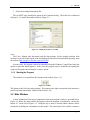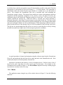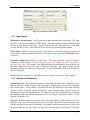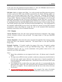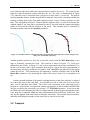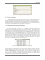
1
ArcNLET: An ArcGIS-Based Nitrate Load Estimation Toolkit User’s Manual Manuscript Completed: June 2011 Prepared by J. Fernando Rios1, Ming Ye1, Liying Wang1, and Paul Lee2 1 Department of Scientific Computing, Florida State University, Tallahassee, FL 32306 Groundwater and Springs Protection Section, Florida Department of Environmental Protection, Tallahassee, FL 32399 2 Rick Hicks, FDEP Contract Manager Prepared for Florida Department of Environmental Protection Tallahassee, FL Revision Sheet Release No. Rev. 1.0.0 Rev. 1.1.0 Date Dec 10, 2010 June 14, 2011 Rev. 1.2.0 June 28, 2011 Rev. 1.3.0 July 22, 2011 User’s Manual Revision Description Initial release Clarification of certain paragraphs. Added description of new software features (risk factor). Expanded the sample problem description. Added a section on the effects of excessive smoothing on the location of peaks and valleys. Added a change to the Transport module (ability to specify input load). Added a quick reference table for parameter units. Minor revisions (formatting and clarifications) Update to v1.1 of the software TABLE OF CONTENTS 1 INTRODUCTION .......................................................................................................................................... 1-1 1.1 1.2 2 SIMPLIFIED MODEL OF NITRATE FATE AND TRANSPORT............................................................ 2-1 2.1 2.2 2.3 3 ORGANIZATION OF THE MANUAL .............................................................................................................. 1-2 ACRONYMS AND ABBREVIATIONS ............................................................................................................. 1-2 GROUNDWATER FLOW............................................................................................................................... 2-1 TRANSPORT ............................................................................................................................................... 2-2 DENITRIFICATION ...................................................................................................................................... 2-3 USAGE ............................................................................................................................................................ 3-1 3.1 PRELIMINARIES ......................................................................................................................................... 3-1 3.1.1 System Requirements ........................................................................................................................... 3-1 3.1.2 Installation........................................................................................................................................... 3-1 3.1.3 Starting the Program ........................................................................................................................... 3-2 3.2 MAIN WINDOW ......................................................................................................................................... 3-2 3.2.1 Menus .................................................................................................................................................. 3-3 3.3 GROUNDWATER FLOW............................................................................................................................... 3-4 3.3.1 Input Layers......................................................................................................................................... 3-5 3.3.2 Options and Parameters ...................................................................................................................... 3-5 3.3.3 Outputs ................................................................................................................................................ 3-6 3.3.4 Troubleshooting ................................................................................................................................... 3-7 3.4 PARTICLE TRACK ...................................................................................................................................... 3-7 3.4.1 Input Layers......................................................................................................................................... 3-7 3.4.2 Options and Parameters ...................................................................................................................... 3-8 3.4.3 Outputs ................................................................................................................................................ 3-8 3.4.4 Interactive Particle Tracking ............................................................................................................... 3-9 3.4.5 Troubleshooting ................................................................................................................................. 3-10 3.5 TRANSPORT ............................................................................................................................................. 3-11 3.5.1 Input Layers....................................................................................................................................... 3-12 3.5.2 Options and Parameters .................................................................................................................... 3-13 3.5.3 Outputs .............................................................................................................................................. 3-16 3.5.4 Troubleshooting ................................................................................................................................. 3-18 3.6 DENITRIFICATION .................................................................................................................................... 3-19 3.6.1 Input................................................................................................................................................... 3-20 3.6.2 Options and Parameters .................................................................................................................... 3-20 3.6.3 Outputs .............................................................................................................................................. 3-20 3.6.4 Troubleshooting ................................................................................................................................. 3-21 4 EXAMPLE ...................................................................................................................................................... 4-1 4.1 INTRODUCTION AND OBJECTIVE................................................................................................................ 4-1 4.2 DESCRIPTION OF SAMPLE DATA ................................................................................................................ 4-1 4.3 DATA PREPARATION .................................................................................................................................. 4-2 4.3.1 Clipping ............................................................................................................................................... 4-2 4.3.2 Re-projection ....................................................................................................................................... 4-5 4.3.3 Merging Line Features with the Water Bodies..................................................................................... 4-7 4.3.4 Hydraulic conductivity and Porosity ................................................................................................... 4-8 4.3.5 Source Locations ............................................................................................................................... 4-10 4.3.6 Spatially Variable Transport Parameters.......................................................................................... 4-10 4.4 RUNNING THE MODEL ............................................................................................................................. 4-11 4.4.1 Groundwater Flow............................................................................................................................. 4-11 4.4.2 Particle Tracking ............................................................................................................................... 4-14 User’s Manual 4.4.3 Transport ........................................................................................................................................... 4-15 4.4.4 Load Estimation................................................................................................................................. 4-16 4.5 VISUALIZATION ....................................................................................................................................... 4-17 5 OTHER NOTES ............................................................................................................................................. 5-1 5.1 5.2 5.3 5.4 5.5 6 UNIT CONSISTENCY QUICK REFERENCE.................................................................................................... 5-1 HETEROGENEOUS AQUIFER PARAMETERS ................................................................................................ 5-2 EXCESSIVE DEM SMOOTHING .................................................................................................................. 5-2 DEM BURNING ......................................................................................................................................... 5-3 OBTAINING THE DATA ............................................................................................................................... 5-4 REFERENCES ............................................................................................................................................... 6-1 User’s Manual LIST OF FIGURES Figure 3-1: Adding the toolbar to ArcMap ................................................................................................3-2 Figure 3-2: Toolbar ....................................................................................................................................3-2 Figure 3-3: Main Program Window ...........................................................................................................3-3 Figure 3-4: Groundwater Flow module .....................................................................................................3-5 Figure 3-5: Particle tracking module .........................................................................................................3-8 Figure 3-6: Interactive particle tracking...................................................................................................3-10 Figure 3-7: Possible scenarios of the particle path crossing the thin water body. The cell sizes of Figures (b) and (c) are 1m and 5m, respectively...................................................................................................3-11 Figure 3-8: Transport module ..................................................................................................................3-12 Figure 3-9: Denitrification module ..........................................................................................................3-20 Figure 4-1: Area of interest within the DEM, indicated by dashed lines...................................................4-3 Figure 4-2: Creating a blank polygon feature class ...................................................................................4-3 Figure 4-3: Beginning an edit session........................................................................................................4-3 Figure 4-4: Define a new clipping region ..................................................................................................4-4 Figure 4-5: Ending the edit session............................................................................................................4-4 Figure 4-6: The newly defined clipping region (rectangle in the center) ..................................................4-4 Figure 4-7: Extract by mask dialog............................................................................................................4-5 Figure 4-8: Clipping the water bodies .......................................................................................................4-5 Figure 4-9: Re-projecting the clipped DEM ..............................................................................................4-6 Figure 4-10: Clipped and projected input data. The septic tanks in the area of interest are shown as the red dots.......................................................................................................................................................4-6 Figure 4-11: Check for floating point type in raster datasets.....................................................................4-7 Figure 4-12: Setting the coordinate system of the data frame ...................................................................4-7 Figure 4-13: Open raster calculator ...........................................................................................................4-8 Figure 4-14: Adding the hydraulic conductivity attribute to the clipping layer ........................................4-9 Figure 4-15: Attribute table of the modified clip layer ..............................................................................4-9 Figure 4-16: Generating the hydraulic conductivity raster ......................................................................4-10 Figure 4-17: Attribute table (partial) of the sources point class...............................................................4-10 Figure 4-18: Zoomed in to the area of interest. A roads layer has been added for reference.................4-11 Figure 4-19: Run the tool by clicking N ..................................................................................................4-11 Figure 4-20: The Groundwater Flow Module..........................................................................................4-12 Figure 4-21: File browser.........................................................................................................................4-13 Figure 4-22: Executing Groundwater Flow module ................................................................................4-13 Figure 4-23: Output magnitude raster......................................................................................................4-14 Figure 4-24: Output direction raster ........................................................................................................4-14 Figure 4-25: Particle tracking module .....................................................................................................4-14 Figure 4-26: Output of the Particle Tracking module ..............................................................................4-15 Figure 4-27: Transport module ................................................................................................................4-16 Figure 4-28: Output of the Transport module ..........................................................................................4-16 Figure 4-29: Nitrate Load Estimation Module.........................................................................................4-17 Figure 4-30: Output load..........................................................................................................................4-17 Figure 4-31: Visualize flow path velocities settings ................................................................................4-18 Figure 4-32: Visualize flow path velocities .............................................................................................4-18 Figure 4-33: Visualization of plumes: settings.........................................................................................4-19 Figure 4-34: Visualization of plumes: concentration distribution............................................................4-19 Figure 4-35: Visualization of plumes: custom contours..........................................................................4-19 Figure 5-1: Effect of smoothing on the location of peaks and valleys.......................................................5-3 Figure 5-2: Downloading DEM using the Seamless Viewer .....................................................................5-5 User’s Manual Figure 5-3: Downloading a DEM using the Seamless Server ArcGIS toolbar ..........................................5-5 Figure 5-4: Downloading NHD data.........................................................................................................5-6 User’s Manual LIST OF TABLES Table 1-1: Abbreviations............................................................................................................................1-2 Table 3-1: Flow module troubleshooting ...................................................................................................3-7 Table 3-2: Particle paths field list ..............................................................................................................3-9 Table 3-3: Troubleshooting particle tracking ...........................................................................................3-10 Table 3-4: Optional parameters in the attribute table of the source locations..........................................3-12 Table 3-5: Field descriptions for the plumes auxiliary file ......................................................................3-16 Table 3-6: Troubleshooting the Transport module...................................................................................3-18 Table 3-7: Denitrification module troubleshooting..................................................................................3-21 Table 5-1: Unit consistency quick reference for parameters......................................................................5-1 User’s Manual 1 INTRODUCTION 1 INTRODUCTION This manual describes the functionality and usage of ArcNLET, an ArcGIS-based Nitrate Load Estimation Toolkit. ArcNLET is intended to model the fate and transport of nitrate in surficial groundwater, originating from onsite wastewater treatment systems (OWTS), namely septic tanks. The program produces an estimated value of nitrate load to specified surface water bodies while taking into account the nitrate removal mechanism of denitrification. The major functions performed by the system are to: Evaluate the groundwater flow directions and magnitudes at discrete points of a domain of interest. Determine the flow paths from septic tanks along which nitrate travels. Estimate the nitrate plumes originating from septic tanks and ending at target surface water bodies. Calculate the amount of nitrate loss due to denitrification that takes place during nitrate transport and calculate the final nitrate load to the target water bodies. The impetus behind creating this software is to have a simple model of nitrate fate and transport that is easy to implement, is integrated into a geographic information system (GIS) for ease of data management and has low input data requirements. While traditional numerical models for groundwater flow and contaminant transport such as MODFLOW, MODPATH and MT3DMS can simulate nitrate fate and transport under complicated field conditions and produce simulated results that may agree well with field measurements, development of these models and generating such agreement generally requires extensive data collection of the study area as well as an experienced modeler. For the purposes of obtaining quick but realistic estimates of nitrate loads to surface water bodies, an approach involving traditional modeling tools may not be ideal since traditional modeling processes can be difficult and time consuming. Additionally, traditional tools do not integrate well, in general, with a GIS. As a result a simplified model is developed to address the concerns with traditional modeling software. As a result of the simpler model, it becomes possible to more effectively integrate the modeling software within the GIS framework as well as make use of some of the advanced spatial analysis tools made available by the GIS. The model is implemented as an extension to ArcGIS from ESRI Inc. Integrating this model with ArcGIS makes it easy to incorporate the spatial nature of data, such as the locations of individual septic tanks and spatially variable hydraulic conductivity and porosity. Finally, embedding the model within ArcGIS facilitates the pre- and post-processing of model data, as well as the visualization of model results. The model is controlled via a graphical user interface (GUI), created as an extension to ArcGIS, and accessed as a tool on the toolbar of the main ArcMap window. In order to facilitate the user interaction, a point and click approach is used, as it is more user friendly than the input file oriented interaction used in traditional groundwater modeling software such as MODFLOW and MT3DMS. User’s Manual Page 1-1 1 INTRODUCTION The focus of this manual is to describe the practical usage of the software package. The underlying model of nitrate fate and transport and the associated algorithmic implementation is described in detail in the technical manual (Rios et al., 2011). Readers of this manual should be familiar with the basics of working with ArcGIS 9.3 and basic scientific and hydrological terminology. 1.1 Organization of the Manual The structure of the manual is as follows: the manual begins with an abbreviated description of the simplified model used in this software, followed by a discussion of the assumptions employed in the model (Chapter 2). After a brief overview of the simplified model, the focus turns to the installation of the software and a general overview on its functioning; a reference to each module is also given (Chapter 3). Finally, in Chapter 4, an example problem is provided for preparing the input files and executing the software. The measurement units used in this manual may vary between metric and imperial units. However required units will always be explicitly stated. In order to make this manual easier to read, a certain typographic convention has been adopted: Model inputs and parameters always appear in bold font. Names of attributes in a shapefile’s attribute table are always shown in a typewriter font. 1.2 Acronyms and Abbreviations In this manual, acronyms or terms that are abbreviated are spelled out in full the first time they appear. The following is a list of acronyms and abbreviations used in this manual: Table 1-1: Abbreviations DEM Digital Elevation Model GIS Geographic Information System. FDEP Florida Department of Environmental Protection GUI Graphical User Interface NED National Elevation Dataset NHD National Hydrography dataset OWTS Onsite Wastewater Treatment System. A septic tank is an example of an OWTS SA Spatial Analyst (extension for ArcGIS) User’s Manual Page 1-2 2 SIMPLIFIED MODEL OF NITRATE FATE AND TRANSPORT 2 SIMPLIFIED MODEL OF NITRATE FATE AND TRANSPORT The simplified model consists of three components (flow model, transport model, nitrate load estimation) which are implemented in four separate modules. The first module (Groundwater Flow) consists of a simplified flow model that uses topography to approximate the water table. The second module (Particle Tracking) calculates flow paths based on the results of the first module. The third module is the Transport module which uses an analytical solution to the advection-dispersion equation to simulate the movement of nitrate. The fourth is the Nitrate Load Estimation module which calculates the nitrate load to surface water bodies. This chapter gives a brief description of each component. For a more detailed description, refer to the technical manual (Rios et al., 2011). 2.1 Groundwater Flow In traditional groundwater modeling, the flow of groundwater is calculated by using Darcy’s law, which requires determining the hydraulic head everywhere in the domain by solving a differential equation (heat equation) given certain initial and boundary conditions. Once the hydraulic head is known everywhere, the hydraulic gradient can be calculated and the flow velocities determined using Darcy’s law. Traditional tools can be difficult to use and require field data that is not usually readily available. Thus, the task is to devise a simplified groundwater flow model that reduces data requirements and integrates well with ArcGIS Because obtaining field data for calculating the hydraulic head of the surficial aquifer (either by solving a differential equation or by interpolation) is difficult and resource intensive, the approach taken by this model is to assume that the hydraulic head distribution of the surficial aquifer (e.g., the water table) is a subdued replica of the topography. A subdued replica means that the shape of the water table can be considered to generally follow the shape of the overlying topography. In other words, if the topography has many peaks and dips, the water table will have fewer peaks and dips and thus is smoother. This assumption is widely used (either explicitly or implicitly) in hydrological modeling. Topographic data is readily available in the form of digital elevation models (DEMs). By processing a DEM, it is possible to generate a subdued replica of the topography, thereby greatly reducing the data requirements of traditional groundwater modeling. In order to use the processed DEM as a proxy for the water table, it is necessary to make several approximations regarding the system. First, the system is assumed to be in the steady state. This means that the generated water table should be considered as an “average” water table over time. The degree to which the water table resembles the topography is controlled by the Smoothing Factor parameter value (described in Section 3.3.2). It is also assumed that the Dupuit approximation is valid in the surficial aquifer. Under the Dupuit conditions, vertical hydraulic gradients can be ignored (i.e., flow is horizontal only and simulating two-dimensional flow fields is sufficient for three-dimensional domains), and the hydraulic gradient is considered to be equal to the slope of the water table. Finally, flow is assumed to occur solely within the surficial aquifer. In other words, unsaturated flow, flow to or from confined aquifers, and the User’s Manual Page 2-1 2 SIMPLIFIED MODEL OF NITRATE FATE AND TRANSPORT interactions between groundwater and surface water are not considered. Additionally, recharge is also not considered. The output of the flow module consists of two rasters, representing the magnitude and direction of seepage velocity, respectively. These rasters are then used by the particle tracking functionality to determine the flow path of an imaginary particle placed at the point where effluent enters the surficial aquifer. The output of the Particle Tracking module is a polyline shapefile containing a set of flow paths from the septic tank locations along the gradient of the water table. These particle paths are then used by the transport module to incorporate flow heterogeneity in the plume calculation. The presence of sinks or pits in the DEM is problematic for generation of flow paths since they cause flow to become trapped. The software provides the option to fill any sinks to their nearest pour point. The pour point is analogous to the location along the rim at which liquid will overflow a bucket that is being filled with water. More details of using the sink filling option are given in Section 3.3.2. 2.2 Transport Nitrate transport is governed by the advection-dispersion equation, which can be solved numerically using general-purpose software such as MT3DMS that can handle inhomogeneous model parameters and arbitrary boundary and initial conditions. However, it is fraught by the similar difficulties as when solving the governing equation for groundwater flow in that it is not easy to use, may have large data requirements, and may come with numerical issues such as issues relating to numerical dispersion and instability. The transport model used for this software is based on an analytical solution to the advection-dispersion equation introduced by Domenico & Robbins (1985). This analytical solution is restricted to considering advection along a single dimension and dispersion along one, two, or three dimensions. Additionally, it is derived assuming homogenous flow fields and homogeneous aquifer properties. Despite these limitations, the greatest advantage provided by the use of an analytical solution is that the concentration of contaminants can be determined anywhere in space at any instant in time without having to numerically solve any differential equations. The Domenico solution used in this software is the two-dimensional, steady-state version with first-order decay (first-order decay is used to simulate denitrification (Domenico, 1987)). This formulation produces a two dimensional plume that is later converted to a pseudo-3D form by extending the 2D solution in the vertical dimension. The use of a pseudo-3D form avoids the large memory requirements of calculating the full 3D solution formulated by Domenico & Robbins (1985). The shape of each plume depends on the groundwater flow field in the vicinity of the nitrate source, as determined by the flow module. Recalling that the analytical solution requires uniform flow, in order to deal with heterogeneity in the flow magnitude, the flow magnitude is averaged along the flow path using the harmonic mean, and this average value is used in evaluating the analytical solution. Heterogeneous porosity is handled by averaging the porosity along the path using the arithmetic mean. Heterogeneous decay coefficients and User’s Manual Page 2-2 2 SIMPLIFIED MODEL OF NITRATE FATE AND TRANSPORT dispersivities are handled by using a constant value for each plume with the possibility of the values varying from plume to plume. The values of the decay coefficient and dispersivities should be representative of the plume. To handle curving flow paths, each plume is individually warped to conform to the flow path, using a 1st order, 2nd order, or thin-plate spline transformation explained in detail in the technical manual (Rios et al., 2011). The output of the Transport module consists of a single raster, representing the combined concentration distribution of all sources. Additionally, an auxiliary point shapefile is created, whose attribute table stores associated plume information (e.g., transport simulation parameters, calculated mass inputs, etc.) for each source. 2.3 Denitrification Denitrification is incorporated in the transport model above using a first-order decay process. The purpose of the Nitrate Load Estimation module is to calculate the amount of nitrate input from septic tanks, nitrate removal due to denitrification, and nitrate load to the target water body using mass balance considerations. Because the transport model calculates the concentration distribution in the steady-state condition, the mass balance equation contains only three terms: the nitrate load rate to the target water body (Fout), the mass input load rate from the source (Fin), and the mass removal rate due to denitrification (Fdn). Fout is calculated by subtracting Fdn from Fin. Fin is calculated by the transport module and takes into account the mass input from both advection and dispersion. Fdn is calculated on a plume-by-plume basis using the definition of first-order decay. The output of the Nitrate Load Estimation module is not a raster or shapefile. Instead, the output consists of a list of nitrate load estimates for water bodies that intersect a flow path. User’s Manual Page 2-3 3 USAGE 3 USAGE 3.1 Preliminaries 3.1.1 System Requirements In order to use the software, the following is required: A Microsoft Windows computer (32 or 64 bit) that meets the minimum requirements for ArcGIS 9.3 or ArcGIS 10.0 ArcGIS 9.3 or ArcGIS 10.0 SA (Spatial Analyst) extension for ArcGIS .NET Framework 3.5 or later versions (Available from www.microsoft.com/net) A computer having a 3 GHz processor and at least 2 GB of system memory is recommended. Under normal program execution, a number of temporary files are created which may require a significant amount of disk space (depending on the current operation and model parameters). As a result, it is recommended to have several gigabytes of free disk space to store these and any other temporary files generated by ArcGIS. 3.1.2 Installation Installation of the software is straightforward by running the appropriate setup package (ArcGIS 9 or ArcGIS 10 setup depending on the version of ArcGIS present on the system). The software must be installed by system administrator. To install an updated version, the previous version must be uninstalled by running Add/Remove Software under Control Panel. With ArcGIS installed, install the extension in the following procedure: 1. Double click the setup.exe installation file. 2. Follow the wizard’s instructions. After successful installation, it is necessary to add the extension to the ArcGIS toolbar as follows: 1. Open ArcMap. 2. In the ArcMap 9.3 menu, click Tools Customize. For ArcMap 10, open the Customize Customize Mode menu. 3. In the dialog that appears, select the entry ArcNLET (Figure 3-1). In case the ArcNLET entry is not present, manual installation is required. To manually add the ArcNLET entry to the list in the Customize dialog, 1. Click the “Add from file…” button in the window of Figure 3-1. 2. Navigate to the installation directory (the default is C:\Program Files\ArcNLET). User’s Manual Page 3-1 3 USAGE 3. Select the ArcMapCommand.tlb file. The ArcNLET entry should now appear in the Customize dialog. Check the box as indicated in Figure 3-1 to enable the toolbar shown in Figure 3-2. Figure 3-1: Adding the toolbar to ArcMap Notes: The User’s Manual (this document) and the data package for the example problem from Section 4 are not included as part of the installation file and must be downloaded separately from the website (http://people.sc.fsu.edu/~mye/ArcNLET) In some cases, the program cannot be uninstalled from the Windows Control Panel (only the option to repair the install appears). In this case, the program may be uninstalled by running the setup.exe file again and selecting the ‘remove’ option. 3.1.3 Starting the Program The software is executed from the buttons on the toolbar (Figure 3-2). Figure 3-2: Toolbar The button on the left is the main program. The button on the right corresponds to the interactive particle tracking functionality (discussed in Section 3.4.4). 3.2 Main Window A brief explanation of the major components of the main program window is provided below. Figure 3-3 shows the main window that appears when the program is launched by clicking the button “N” on the left of Figure 3-2. Along the top, a menu is located which contains various commands, including the command to run the model. The central part of the window contains a User’s Manual Page 3-2 3 USAGE set of tabs where each tab corresponds to a specific functionality (module) of the model. Detailed descriptions of each module are given in Sections 3.3 – 3.6 of this manual. This separation of functionality makes the model execution more flexible as it enables one to run the model in pieces. For example, the Groundwater Flow tab is concerned only with calculating the groundwater seepage velocity. The output of this module (two rasters representing the direction component and the magnitude component of the velocity vector) can then be used by the subsequent stage of the model (the Transport module) at a later time. The lower part of the window contains the message log. When the model is executed, the current operation is displayed along with a time stamp. Error messages are also printed to this log. The log is useful for monitoring the progress of the model run and for displaying any error messages (both model and system messages) which can aid in troubleshooting. When requesting technical assistance, please provide the text of the message Log as well as screenshots of any relevant error boxes. The log may be copied straight from the text box or it may be saved directly to a file by clicking the blue icon in the lower right corner of the message log (near the scrollbars). Figure 3-3: Main Program Window A typical procedure of nitrate load estimation using the software starts from the Groundwater Flow tab, moving through the tabs from left to right, and ends at the Denitrification tab. Each module (tab) may be executed separately from the rest. Input data is included in the model by a series of dropdown boxes. Each box shows a list of layers in the active map that are of the correct type for that input. For example, in the Groundwater Flow module in Figure 3-3, the Water Bodies dropdown will only contain polygon layers that are currently in the active map. 3.2.1 Menus The application menu, along the top of the window shown in Figure 3-3, has the following functions: User’s Manual Page 3-3 3 File USAGE Clear Temp Folder: clears all files in the directory specified by the %temp% environment variable; this is the system temporary folder and can be located by typing “%Temp% in the Address box of Windows Explorer. Do not execute this function if there is a model run in progress. If there are unusual errors being generated, or the output is not as expected, execute this function before new execution starts. Sometimes, ArcGIS will give strange errors which disappear after clearing the temp folder, hence the reason for this function. Exit: exits this software. Execute Groundwater: executes the Groundwater Flow module. Particle tracking: executes the Particle Tracking module. Transport: executes the Transport module. Denitrification: executes the Nitrate Load Estimation module. Settings Output Intermediate Calculations: During a modeling run, a series of operations are carried out by the software to produce the final result. When the Output Intermediate Calculations option is enabled, at the end of each operation within the currently executing module, the data produced by each intermediate step will be saved and added as a new layer in the current map. This allows the user to examine the output after each calculation step. Each new layer will be uniquely named which allows it to be matched to the operation that produced it by looking up the corresponding entry in the message log. A scenario where this function would be useful is for the flow module, since it allows the user to examine the smoothed topography (which is not output as part of a normal model run). Show Help File: Shows this document. In order for this to work, this document must be downloaded from the software website, placed in the software installation folder and named “users_manual.pdf”. About: Shows the software version. Help 3.3 Groundwater Flow The purpose of the Groundwater Flow module (Figure 3-4) is to generate two rasters representing the magnitude and direction components of the groundwater flow velocity vector. Normally, for a new software execution, this will be the first module that needs to be run since all other modules are dependent on the groundwater velocity for their calculations. If groundwater velocity does not change in a new execution, there is no need to run this module again. This module uses a DEM, to approximate the hydraulic gradient which is then used in combination with aquifer properties to calculate groundwater velocity. Inputting the DEM and aquifer properties is described below. User’s Manual Page 3-4 3 USAGE Figure 3-4: Groundwater Flow module 3.3.1 Input Layers DEM surface elevation map: Used to generate an approximation to the water table. This input must be a raster layer (preferably in GRID format). Note that a higher resolution DEM does not necessarily give better results, since a coarser DEM may better approximate the water table (Wolock and Price, 1994). This DEM will be the base for all processing in this module. Water bodies: Must be a polygon type layer. This dataset is used to determine the locations of water bodies to which groundwater will flow. This input is only used when the Fill Sinks option is selected. Hydraulic Conductivity: Must be a raster layer. This input represents a map of hydraulic conductivity for the domain. The linear units of the hydraulic conductivity must be the same as the units of the DEM. For example, if the DEM has linear (ground distance) units of meters, the hydraulic conductivity must have units of meters per unit time. The output seepage velocity magnitude will have the same units as this input. It is the responsibility of the user to ensure all units are consistent. Porosity: Must be a raster layer. This input represents a map of soil porosity for the domain. 3.3.2 Options and Parameters Smoothing Factor: This controls the number of smoothing iterations that are performed on the DEM to generate a subdued replica of the topography. Higher numbers mean more smoothing and a flatter replica. As the number of iterations increases, the difference in the output from one iteration to the next becomes smaller and smaller. Values normally range between 20 and 100 depending on the specific application area. The optimum value may be determined by comparing the smoothed DEM with hydraulic head observations; an example is provided in Volume 3 of the manual. The default is 20. Z-Factor: If the horizontal measurement units of the input DEM are different than the vertical units, this value serves as a conversion factor to convert the vertical unit into the horizontal unit, which is necessary in the slope calculations. For example, if the horizontal units are meters and the vertical units are feet, the z-factor is 0.3048, since one foot equals 0.3048 meters. If the units User’s Manual Page 3-5 3 USAGE are the same, this value should be left at the default of 1. Note, the Z-Factor cannot be used to convert between two different horizontal measurement units. Fill Sinks: Enables or disables sink filling. It is useful to enable sink filling when the presence of sinks or pits in the DEM causes flowlines (generated by the Particle Tracking module, see Section 3.4) to become trapped before they reach a water body. Disabling sink filling (the default setting) is useful in circumstances where expansive flat areas are created due to the filling of large valleys. Therefore, leaving sink filling disabled can be advantageous, even if some pits remain after smoothing, but only if the pits do not interfere with the flow lines. As part of the sink filling functionality, areas in the smoothed input DEM that are overlain by a water body will be superimposed onto the sink filled DEM, thereby preserving areas of low elevation in large water bodies (smaller water bodies will likely have been smoothed away). This superposition of the smoothed, unfilled DEM in areas where water bodies are present can be useful in limited circumstances where sink filling has caused the cells of the smoothed DEM immediately bordering a water body to flow in unnatural directions. 3.3.3 Outputs Velocity Direction: Each cell in this raster represents the direction component of the seepage velocity, in degrees clockwise from grid north. The output format is of the type IMAGINE Image (.img) Velocity Magnitude: Each cell in this raster represents the magnitude of the seepage velocity, in the same units as the hydraulic conductivity. The output format is of the type IMAGINE Image (.img) Hydraulic Gradient: If checked, enables the output of the raster of hydraulic gradient magnitude. The output format is of the type IMAGINE Image (.img). This output is for informational purposes only (e.g., for the examination of the gradient values) and it is not required by any of the other modules. Notes: Inputs from geodatabases are not supported at this time. All datasets must be shapefile based. The input rasters (DEM elevation, hydraulic conductivity and porosity) should ideally be all of the same spatial extent. Otherwise, the output raster of velocity magnitude will have the extent of the smallest input raster. The direction raster will have the same extent as the input DEM. Even though the flow module allows non-square grid cells, it is recommended that the input rasters have square cells, since inaccuracies may be introduced in the calculations if the cells are rectangular. The user should ensure that the sizes of the cells are the same for all rasters. It is very important that units be consistent. For example if the values of hydraulic conductivity are in meters per day, the input DEM should be in units of meters as well. User’s Manual Page 3-6 3 USAGE 3.3.4 Troubleshooting Table 3-1 lists some possible issues that may be encountered during model execution along with a possible cause and a suggested solution. Note that the error messages may appear for reasons other than those listed. Technical support is available via the software release website http://people.sc.fsu.edu/~mye/ArcNLET. Table 3-1: Flow module troubleshooting Error Cause Solution Message “Could not set analysis window” appears in the log when calculating Darcy Flow The spatial reference of one or more of the input datasets is different than the dataframe Make sure all datasets have the same datum, coordinate system and projection as the dataframe Error when the Fill function executes Unknown Try converting the input DEM to GRID format Assembly loading errors or E_INVALIDARG errors appear in the log Unknown Close ArcGIS, clear out the windows temp folder and/or restart the computer. Make sure there is enough disk space and RAM available. Message “System.IO.FileNotFoundException: No spatial reference exists.” appears after finding flat areas Unknown Run the Clear Temp Folder function and Restart ArcGIS. Message “Exception from HRESULT 0x80040351” appears when loading the water bodies Geodatabase data sources are not supported Convert the dataset into a shapefile. The shapefile does not exist or is corrupted Make sure that the file exists and is readable. 3.4 Particle Track The Particle Tracking module (Figure 3-5) is to calculate the path that a synthetic particle travels in a flow field from a specified location, a septic tank in this study. The flow field is calculated using the Groundwater Flow module. The path calculated by this module will be used to calculate advective transport of the contaminant plume from any given septic tank. 3.4.1 Input Layers Source locations: A point feature layer specifying the locations of the nitrate sources (i.e., septic tanks). User’s Manual Page 3-7 3 USAGE Water bodies: The locations of water bodies used by the Groundwater Flow module. If a flow path intersects a water body, the path is terminated at the water body. Figure 3-5: Particle tracking module Velocity magnitude: The magnitude raster generated by the flow module. This information is used to calculate an average velocity (harmonic mean) value along the flow path for use by the Transport Module. Velocity direction: The direction raster generated by the flow module. Porosity: The soil porosity used by the flow module. This information is used to calculate an average porosity (arithmetic mean) value along the flow path for use by the Transport module. 3.4.2 Options and Parameters W.B. Raster Res. (Water Body Raster Resolution): The resolution (in map units) used to convert the water bodies polygon to raster. The default value is automatically set to one half of the velocity direction raster cell size, which is in turn determined by the DEM resolution. This value should only be changed if the default does not provide satisfactory results as explained in the troubleshooting notes and Figure 3-7c. Step Size: The length of each segment (in map units) of the flow path. The default is automatically calculated to be equal to the value of W.B. Raster Res. This value should only be changed if the default does not produce satisfactory results (see troubleshooting notes below). Max Steps: The maximum number of steps to take before terminating the path. This parameter prevents infinite loops by ensuring there is always a stopping criterion for particle tracking. The default should suffice for most circumstances. 3.4.3 Outputs Particle Paths: A polyline shapefile containing line segments representing the path of a particle starting from each source point and moving through the flow field. Any given path from a source point (i.e., septic tank) to a water body is composed of a series of line segments (of length Step Size) in which the hydraulic conductivity and soil porosity are assumed constant within each segment. Each entry in the shapefile’s attribute table corresponds to a single segment. User’s Manual Page 3-8 3 USAGE Table 3-2 shows the fields contained in the shapefile’s attribute table. This table is used by the Transport module to calculate the average velocity and porosity values. Details of the attribute table are only needed for advanced uses of the software (e.g., visualization discussed in Section 4.5); it is not necessary for general users to understand the meaning of each item of the table. Table 3-2: Particle paths field list Field Name PathID Description SegID The ID of the current segment. This ID is assigned in sequence with 0 corresponding to the first segment in the flow path for any given PathID. TotDist The total cumulative travel distance for the current segment. TotTime The total cumulative travel time for the current segment. SegPrsity The porosity at the starting point of the current segment. SegVel The velocity at the starting point of the current segment. SegVelTxt The velocity at the starting point of the current segment, in a text format (for manual inspection purposes). WbID The FID of the water body that intersects the starting and/or ending point of the current segment. If no water body intersects the current segment, then this value is -1. In a sequence of segments corresponding to a given PathID, only the final segment in the sequence should have a value other than -1. If the sequence does not terminate at a water body, then all segments will have a value of -1. PathWbID The FID of the destination water body. The value of this field is the same for each segment and is equal to the value of WbID of the final segment in the path. The FID (unique identifier) of the corresponding point (i.e., septic tank location) in the Source Locations point feature class. All path segments corresponding to the same source will have the same PathID value. 3.4.4 Interactive Particle Tracking Interactive particle tracking can be conducted by clicking the “T” icon in the toolbar (see Figure 3-2). The interactive particle tracking functionality (Figure 3-6) differs from the noninteractive particle tracking module described above in that with interactive particle tracking, it is possible to specify a source at any location by clicking the location on the map, rather than specifying it through a shapefile. The parameters are the same as those of the non-interactive particle tracking module except for the following listed below: User’s Manual Page 3-9 3 USAGE Figure 3-6: Interactive particle tracking Name: The name of the shapefile into which the particle path will be saved. It is equivalent to the outputs of particle paths described in Section 3.4.3. X, Y: The location (in map units) at which to conduct particle tracking. These values can be modified manually or they can be set by clicking an area in the map. 3.4.5 Troubleshooting Table 3-3 lists some possible issues that may be encountered during model execution along with a probable cause and a possible solution. Note that the error messages may appear for reasons other than those listed. Technical support is available via the software release website http://people.sc.fsu.edu/~mye/ArcNLET. Table 3-3: Troubleshooting particle tracking Error Cause Solution Processing intermittently aborts unexpectedly Interacting with the GUI sometimes causes an error in SA execution Once processing has started, do not interact with the GUI until processing completes. Particle paths appear as vertical or nearly vertical lines. The selection of input magnitude and direction layers have been reversed. Make sure the correct magnitude and direction raster are selected. Message “Exception from HRESULT 0x80040351” appears when loading the water bodies Geodatabase data sources are not supported. Convert the dataset into a shapefile. The shapefile does not exist or is corrupted. Make sure that the file exists and is readable. Notes: It is possible that particle paths travel through a water body, depending on the value of the W.B. Raster Res. parameter and the value of the Step Size parameter. The reason this phenomenon is related to the Step Size is explained in Figure 3-7a, which shows a small creek that is 6 m wide. The thin blue lines represent flow paths. Note that the leftmost line crosses the User’s Manual Page 3-10 3 USAGE creek while the other four exhibit the expected behavior and do not cross it. The reason for this behavior is that the leftmost particle path does not “see” the creek, is demonstrated in Figure 3-7b, when the creek is converted from a polygon to a raster with a 1 m cell size. The particle tracking algorithm detects whether the path has reached the water body by checking whether the starting or ending point of the flow path segment overlaps a raster cell that represents a water body. The red segment in Figure 3-7b shows that the segment “skips” over the creek because the segment length is too large and is positioned in such a way that both the starting and ending points do not coincide with the location of the creek. This situation may be remedied by selecting a smaller value for the Step Size parameter. a) b) c) Figure 3-7: Possible scenarios of the particle path crossing the thin water body. The cell sizes of Figures (b) and (c) are 1m and 5m, respectively. Another possible reason for a flow line to cross the creek is that the W.B. Raster Res. is too large to accurately represent the creek. This scenario is shown in Figure 3-7c, in the area indicated by the red box. In Figure 3-7c, the creek is represented with a raster resolution of 5 m. In this case, because of the coarse resolution, there may be a gap in the raster representation of the water body which may enable the flow path to “leak” through the gap indicated by the region within the red box. This situation may be remedied by selecting a smaller value of the W.B. Raster Res. parameter or by increasing the width of the narrow creek (if it is reasonable to do so). Another potential problem of the particle tracking function is that flow path may be trapped in a sink or pit close to the water body. It is possible for a sink to exist very close to the water body, even if sinks have been filled. This is due to the conversion of the water body from a polygon to a raster format, in conjunction with the superposition of the smoothed, unfilled DEM in areas overlain by the water body (see Section 3.3.2, Fill Sinks parameter). It may occur that the DEM raster cell containing the sink lies slightly outside of the polygon representation of the water body but is contained within the raster representation of the water body. In this case, flow may become trapped in the sink before reaching the water body. This scenario may be treated by manually modifying the boundary of the water body to extend over the sink. 3.5 Transport User’s Manual Page 3-11 3 USAGE After generating particle paths in the above operation, the Transport module (Figure 3-8) calculates the distribution of nitrate concentration using the steady-state, 2D version of the Domenico solution. Note that the calculations performed by this module are the most resource intensive out of all the modules. If there is not enough memory or free disk space, calculations may fail unexpectedly. If this happens, users need to reduce the resolution or conduct the simulation for a sub-area of the domain. Figure 3-8: Transport module 3.5.1 Input Layers Source locations: This layer specifies the locations of the contaminant sources. This point feature class may optionally contain several numeric (FLOAT) fields in its attribute table that allow for the specification of several transport parameters on a source-by-source basis. The fields that are allowed are described in Table 3-4. Table 3-4: Optional parameters in the attribute table of the source locations Field Name Description Corresponding GUI Parameter N0_Conc The initial concentration of the source plane. C0 [M/l^3] decayCoeff The first-order decay coefficient of the analytical solution. Decay Constant [1/T] dispL The longitudinal dispersivity αL [L] dispTH The transverse horizontal dispersivity αTH [L] The field names must be named exactly as shown in the table and they must be of type FLOAT. If the selected Source locations layer contains any of the allowed fields in Table 3-4, the corresponding text box in the GUI (Figure 3-8) will be highlighted yellow. Placing a “-1” in a highlighted text box will cause the software to use the value specified in the attributes table for each entry in the table. This means that it is possible to specify different parameter values for User’s Manual Page 3-12 3 USAGE each source. If the value in the highlighted box is set to a value greater than or equal to zero, the value in the box will override the values in the attribute table. Water bodies: Specifies the locations of water bodies. This layer serves to ensure that each plume terminates at the boundary of any water body. It is the same input as that used in the Particle Tracking module. Particle paths: The particle paths corresponding to the Source locations, as calculated by the flow module. It is the output file of the particle tracking module. Using this file, the Transport module will calculate the average velocity (harmonic mean) and porosity (arithmetic mean) along each flow path. These values are then used for the calculation of each plume. 3.5.2 Options and Parameters Solution type: The form of the Domenico solution to use. The available options are: DomenicoRobbinsSS2D – The two dimensional, steady-state Domenico solution without decay (i.e., without denitrification). DomenicoRobbinsSSDecay2D – The two dimensional, steady-state Domenico solution with decay. C0: The concentration of the source plane. Its range is between 0 and 80 mg/l in literature, and the default is 40 units (e.g., mg/l). If this field is set to -1, the value in the Source locations attribute table will be used instead, if it is present (see the description of the Source locations input layer). Min: If the value of the Domenico Bdy. parameter is set to Specified_Input_Mass_Rate, then this input will be enabled. The value of the Min parameter represents a known input mass rate, in units of mass per time, from the constant concentration source plane. When this parameter is specified, the value of the Source Dim. Z parameter is automatically calculated. The mass units of Min must be the same as the mass units of C0 and the time units must be the same as the time units of the flow velocity magnitude. A value of 20000 mg/day per septic tank is a reasonable starting point for model calibration. Source Dim.: The dimensions (in map units) of the Domenico source plane (Y and Z). Note that although a 2D version of the Domenico solution is used, the Z value is still required since it will be used to convert the 2D solution into a pseudo-3D form by extending the 2D solution vertically downwards. The Y value can be estimated by measuring the width of the drainfield in the direction approximately perpendicular to groundwater flow. Z should be estimated from measured plume thickness values. The default values are Y=6 m and Z=1.5 m. The value of Z should not normally exceed three meters. These values are in units of meters and should be changed accordingly if the map units are not meters. The units of Y and Z must have the same length units as the flow velocity magnitude. If the Domenico Bdy. parameter is set to Specified_Input_Mass_Rate, then the Z source dimension is calculated automatically. If the User’s Manual Page 3-13 3 USAGE Domenico Bdy. parameter is set to Specified_Z, then the Z value can be entered and Min is calculated automatically. Plume cell size: The resolution of the grid (in map units) over which the Domenico solution will be evaluated. A smaller value will yield higher resolution plumes, at the expense of increased computation time and memory usage. Setting the cell size to a value that is too small when there are many plumes will likely result in out-of-memory exceptions or other unexpected errors. In order to adequately represent the plume, the cell size should be between 5 and 30 times smaller than the source width. By default, the cell size will be set to a value 15 times smaller than the value of Source Dim. Y. For exploratory purposes, this value can be set much higher in order to speed up calculations. The plume resolution can be different from that of DEM (and generally should be smaller) and the one used in particle tracking, rendering the model execution more flexible. The units of this parameter must have the same length units as the flow velocity magnitude. Although a general guideline is provided for reasonable values of this parameter, the smaller Plume cell size, the more accurate the solution. Dispersivities: αL and αTH are the longitudinal and horizontal transverse dispersivities respectively. Approximate values may be obtained from literature for a given soil type (e.g., Freeze and Cherry, 1979). The defaults of 2.113 m/day and 0.234 are based on a model by USGS scientists of the Naval Air Station in Jacksonville. Again, if the map units are not meters, this number should be changed accordingly. If these fields are set to -1, the values in the Source locations attribute table will be used instead, if they are available in the table (see the description of the Source locations input layer). The units of αL and αTH must have the same length units as the flow velocity magnitude. Decay constant: The first-order decay constant. This constant controls the amount of nitrate loss due to denitrification. An approximate value may be obtained from the literature (e.g., McCray, 2005). The default value is 0.008 day-1. If this field is set to -1, the value in the Source locations attribute table will be used instead, if it is available in the table (see the description of the Source locations input layer). The units of this parameter must have the same time units as the flow velocity magnitude. Volume conversion factor: This factor is used to convert volumes calculated from the units of length to the volume units used for concentration. For example, if the value of N0_Conc was specified using the unit of mg/l, and the length units (units of the cell size, source dimensions, dispersivities, and length portion of the flow velocity magnitude units) are in meters, the conversion factor is 1000 since 1000 liters equals one cubic meter. The correct conversion factor is CRITICAL so as to be able to calculate the nitrate load correctly. Control point spacing: This parameter is used to warp the plume to specific flow paths. It specifies the number of cells along the plume centerline (starting from the source location) which separates the control points used for warping. The control point spacing, along with the plume length and the value of the Plume Cell Size determines the number of control points for any given plume. The minimum number of points required per plume varies depending on the warping Method parameter. For spline transforms, the minimum number of points allowed is ten, for second-order polynomial transforms it is six, and for first-order transforms, three is the User’s Manual Page 3-14 3 USAGE minimum. A smaller Control point spacing yields, in principle, a more accurate warp at the expense of a (theoretically) longer computation time. The amount of increase in computation time depends on the Method used for warping. Setting the Control point spacing too small may a) unnecessarily increase computation time and b) cause the warp to fail if the flow path is nearly straight, especially for spline transforms. Setting this value too large is not problematic since the software automatically ensures there are sufficient control points available for warping. If the algorithm cannot generate a sufficient number of points (likely due to the fact that the plume is too short, or has a cell size that is too large), then the warp will fail. The default value (48 cells) should be acceptable for most applications. For example, if the spacing is set to 48 cells, control points will be spaced 48 raster cells apart. If less than the required number control points are possible (due to a short plume for example), the program adjusts this number to an appropriate value on-the-fly. If, after adjusting spacing on-the-fly, the number-of-points requirement cannot be met, the warp will fail and the plume will be discarded. If a high number of plumes are discarded due to this reason, a possible solution is to increase the plume resolution, i.e., decrease the Plume Cell Size value. Method: The warping algorithm to use. Spline – Thin-plate spline transform. This is the default since it has the best overall result in terms of computational time and numerical accuracy. Polynomial2 – 2nd-order polynomial transform. This can be used in special cases where the flow paths are simple and are generally arc-shaped. In this case, the 2nd-order polynomial warp may yield slightly more accurate results. Polynomial1 – 1st-order polynomial transform (affine transform). This transform should only be used for troubleshooting purposes or when the flow path is in the form of a straight line. Use approximate warp: Uses an approximate transformation instead of an exact one. This significantly increases computation speed at the expense of slightly less accurate warps. It is recommended to leave this option enabled. Threshold Conc.: The threshold value below which the nitrate concentration will be considered zero. This value can be used to speed up computation and reduce memory requirements by essentially discarding portions of the plume that fall below a certain threshold value. The units of this number are the same as the units of N0_Conc. Setting this value too low may increase resource utilization beyond the capabilities of the machine on which the model is being run. Setting this value too high may result in discarding significant portions of the plume, resulting in large mass balance errors. If the units of N0_Conc are in mg/l, then the default of 1E-6 mg/l should be sufficient for most applications. If the concentration units are NOT in mg/l, this value should be changed to the equivalent value in the correct units. Post processing: This setting controls how the plumes that intersect a water body are handled (see the technical manual for more details): User’s Manual Page 3-15 3 USAGE None – When the plume reaches a water body, the plume terminated with a straight line perpendicular to the flow direction. This option can be used when the other methods are too slow, or for troubleshooting purposes. Medium – Plumes are all post-processed as a single raster. Plumes that reach a water body are terminated with a shape that conforms to the shape of the water body boundary. This option will work in cases where the configuration of the water bodies is simple (e.g., a single large water body). This is the default selection. Full – Plumes are processed individually. This option is the slowest of the three and, depending on the number of plumes, is significantly slower than the Medium option. When there is only a single plume, Medium and Full produce exactly the same result. In cases where plumes appear to cross small creeks or ditches, or there are other complicated water body configurations, this option or the None option should be used. 3.5.3 Outputs Plumes: The raster containing the concentration distribution of the calculated plumes. An additional file, the “info” file, will be saved in the same disk location as the plumes raster, with the same name as the plumes raster having except having the “_info” suffix. The info file is a shapefile containing points corresponding to each source location. Each point has an associated set of attributes that describe the plume corresponding to that source (the parameters used to calculate the plume, the warping and post processing methods etc). Since some of this information is used by the denitrification module, the values in the attribute table should not be modified manually. For reference purposes, the field descriptions of the “info” file are given in Table 3-5. In the table, only the fields indicated with an asterisk are used by the Nitrate Load Estimation module to calculate loads. The fields not used for calculation are for informational/archival purposes only. Even so, they should not be modified as they serve to record the parameters used for each plume. Additionally, the presence of and consistency (with the supported software functionality) will be checked for all parameters. Table 3-5: Field descriptions for the plumes auxiliary file Field Name PathID Description The PathID of the flow path used to generate a particular plume. Values in this field correspond to values of the PathID field of Table 3-2. Is2D 1 – Indicates the plume is pseudo 3D. 0 – Indicates the plume is fully 3D (not currently supported). domBdy 1 – The source plane has a specified mass input rate 2 – The source plane has a specified Z dimension decayCoeff The decay coefficient. avgVel The velocity value. Obtained by averaging along the flow path. User’s Manual Page 3-16 3 USAGE avgPrsity The porosity value. Obtained by averaging along the flow path. dispL The longitudinal dispersivity dispTH The transverse-horizontal dispersivity dispTV The transverse-vertical dispersivity (not currently supported) sourceY The Y source dimension sourceZ The Z source dimension MeshDX The plume cell size in the x-direction (same as MeshDY) MeshDY The plume cell size in the y-direction (same as MeshDX) MeshDZ The plume cell size in the z-direction (same as sourceZ) plumeTime The time at which the plume is calculated. This value is -1 for steady-state plumes (only steady-state solutions are supported currently) pathTime The total time that flow takes from the start of the flow path to the end. plumeLen The length of the plume (in map units) pathLen The total length of the flow path. plumeVol The total plume volume, calculated by summing the volumes of the individual plume cells. Each plume cell has dimensions MeshDX x MeshDY x MeshDZ. msRtInNMR The mass input rate of nitrate from the Domenico constant concentration plane due to advective and dispersive flow. The method used to calculate this is similar to numerical modeling software in which the inflow is calculated on a cell-by-cell basis, given the size of the source plane, groundwater flow velocity and concentration gradients. This is for information purposes as it is not used in any calculations massInRate* The mass input rate of nitrate from the Domenico constant concentration plane due to advective and dispersive flow. This number is calculated based on an analytical solution (see the technical manual for details) massDNRate* The nitrate mass removal rate due to denitrification. This value is calculated for each plume cell using the definition of first-order decay (see the technical manual for details). User’s Manual Page 3-17 3 USAGE srcAngle The orientation of the Domenico source plane, in degrees clockwise from north. Warp The warping algorithm used. 1 – Spline 2 – 2nd order polynomial 3 – 1st order polynomial PostP The post-processing method. 0 – None 1 – Medium 2 – Full N0_conc The source concentration VolFac The volume conversion factor nextConc An approximate value of the concentration gradient at the source. This value corresponds to the concentration of the cell located at x=MeshDX, y=0 threshConc The concentration threshold value. WBId_plume* Records the FID of the waterbody that the plume discharges to. If the plume does not reach a water body, this value is -1 WBId_path* Records the FID of the water body that the flow path reaches. If the flow path does not reach a water body, this value is -1 3.5.4 Troubleshooting Table 3-6 lists some possible issues that may be encountered during model execution along with a probable cause and a possible solution. Note that the error messages may appear for reasons other than those listed. Technical support is available via the software release website http://people.sc.fsu.edu/~mye/ArcNLET. Table 3-6: Troubleshooting the Transport module Error Cause Solution If there are many sources, depending on the choice of parameters, plume calculation may fail unexpectedly. The system has insufficient memory or disk space. Free up memory by closing other program. Free up disk space by clearing the temp folder using the Clear Temp Folder function in the menu. Split up the input file (paths, or sources) into multiple parts User’s Manual Page 3-18 3 USAGE (either split up the point sources or the particle paths). Junk is output in the plumes raster after warping In certain configurations of the warping control points (e.g., when many points fall on a path that is almost a straight line), warping may succeed but the plume raster consists of garbled data. Try a different warping method and/or different control point spacing. Some plumes are not calculated. If the plume is too short, warping will fail due to an insufficient number of control points. Decrease the value of the Plume cell size parameter The septic tank may be inside a water body. Move the septic tank outside the water body or modify the water body boundary if appropriate. Note: if a plume is not calculated for any reason, the input load to the system due to that source will be ignored. Message “Exception from HRESULT 0x80040351” appears when loading the water bodies Geodatabase data sources are not supported. Convert the dataset into a shapefile. The shapefile does not exist or is corrupted. Make sure that the file exists and is readable. UAC prompt may appear when executing the module under Windows Vista/7 Windows Vista/7 security Windows may ask permission to execute the program AqDnWrapper.exe. Simply grant permission and the module should execute normally 3.6 Denitrification The Nitrate Load Estimation module (Figure 3-9) uses the output from the transport module to calculate the load to the target water body. The load is calculated by summing the individual contributions of each plume for each water body. User’s Manual Page 3-19 3 USAGE Figure 3-9: Denitrification module 3.6.1 Input Plumes info: The auxiliary info file associated with the plumes raster calculated by the transport module. The information contained in the attribute table of this file should not be manually modified. Only point feature layers whose name has the “_info” suffix will be shown in the dropdown. 3.6.2 Options and Parameters Risk Factor: The values in the Mass Output Load column will be multiplied by the risk factor for each water body. The resulting number is then shown in the Mass Output Load x Risk Fac. Column. The value of risk factor should be determined by the user. 3.6.3 Outputs The output is a list showing the calculated load values for each water body. This allows investigating spatial distribution of the nitrate load along the water bodies of interest. The output columns are: Water body FID: The FID of the water body where all flow paths terminate. The water body corresponding to this FID can be determined using the ArcMap Information tool or by opening the attribute table of the Water bodies feature class and selecting the entry with the corresponding FID. The selection will then be shown on the map. Mass output load: The total estimated nitrate load to the water body with the given FID in units of mass per time. The unit of mass is the same as the mass unit used in the source concentration (e.g., mg in mg/l). The unit of time is the same as the time unit used in the velocity flow field units calculated by the flow module (e.g., day in meter/day). This output load is equal to the Mass removal rate subtracted from the Mass input load. Mass output load x Risk Fac.: The Mass output load multiplied by the Risk Factor. Mass removal rate: The total amount of mass being removed due to denitrification, modeled as a first-order decay process in units of mass per time. The units are the same as the units of Mass output load Mass input load: The total input mass flux rate into groundwater due to the constant concentration plane source of the Domenico solution, taking into account both advection and dispersion. Details of the concentration plane and the evaluation of mass input load are described in the technical manual. User’s Manual Page 3-20 3 USAGE The output may be exported to a tabular format which can be opened in any spreadsheet program by clicking on the small blue icon on the far right of Figure 3-9. This will export the data shown in the table to a comma separated list of values. 3.6.4 Troubleshooting Table 3-7 lists some possible issues that may be encountered during model execution along with a probable cause and a possible solution. Note that the error messages may appear for reasons other than those listed. Technical support is available via the software release website http://people.sc.fsu.edu/~mye/ArcNLET. Table 3-7: Denitrification module troubleshooting Error Cause Solution Error message “All plumes must be xxx” or “All plumes must have xxx” appears where xxx can be various messages. The likely cause is due to the user modifying the associated “_info” table generated by the transport module. The “_info” file should not be changed Re-run the transport module User’s Manual Page 3-21 4 EXAMPLE 4 EXAMPLE 4.1 Introduction and Objective The final goal of this tutorial is to show an example workflow process for using this software. In this chapter, the basic steps required to prepare model input data and to run the model are discussed. Program features related to this specific example will also be explained. The desired output of the model in this example is the nitrate load due to septic tanks on the target water body in the Lakeshore neighborhood of Jacksonville, Florida. The data used in this tutorial is provided as part of the “lakeshore_example” package which can be downloaded from the software website. The basic workflow in a typical modeling run is: 1. 2. 3. 4. 5. 6. Prepare input data. Enter the data into the input fields of the Groundwater Flow module. Use the output of the flow module as input to the Particle Tracking module. Use the output of the Particle Tracking module as input to the Transport module. Use the output of the Transport module as input to the Nitrate Load Estimation module. Re-adjust model parameters if the results are not satisfactory. Go back to step 2, 3, 4 or 5 as required. 4.2 Description of Sample Data In this example we will focus on the Lakeshore neighborhood of Jacksonville, Florida. In this neighborhood, houses are served by in-situ water treatment installations (i.e., septic tanks). A map of tanks is provided by the Florida Department of Environmental Protection where the location of the septic tank was assumed to be at the center of the property. In order to generate a map of hydraulic gradient, a DEM of the area was obtained from the NED service maintained by the USGS. This DEM has a horizontal resolution of 1/3 arc seconds (approximately 10 meters). Although higher resolution data may be available, it may not be appropriate to use a higher resolution because the increased detail is not well suited for hydrologic simulations (Wolock and Price, 1994). To determine the locations of water bodies that may be impacted, data was obtained from the FDEP in the form of an ArcGIS shapefile. Groundwater flow and transport parameters used in this example are taken from literature. This example therefore serves only for the purpose of training, not for realistic estimation of nitrate load in the Lakeshore neighborhood. The sample data may be downloaded from http://www.people.sc.fsu.edu/~mye/ArcNLET under the Downloads section. Extract the lakeshore_example.zip file to a folder on your computer. Preferably, the path should not contain folders with spaces in their names as this may cause some ArcGIS tools to fail to execute. The zip file contains a fully completed model run as well as all of the processed input files required to generate the results of the provided run. It also has a subfolder called OriginalData that contains the unprocessed data, i.e., an unclipped and unprojected DEM (lakeshore.img), and unprocessed (but clipped) water body data (polygon and line data). Processing of the original data is described in the following section. User’s Manual Page 4-1 4 EXAMPLE If not using the provided sample data, the procedure of obtaining the DEM data from a website of the U.S. Geological Survey is given in Section 5.4. Other data needed for running the software (e.g., the water body polygons) can be obtained in the same manner from an appropriate database including that of the Florida Department of Environmental Protection. 4.3 Data Preparation If using the processed sample data provided in the tutorial data download package, proceed directly to Section 4.4 of running the model. The unprocessed DEM and water body data is provided for reference purposes in the OriginalData directory in the example data package. For illustration purposes, this section outlines the required steps to prepare data used in the model, starting from the unprocessed data contained in the OriginalData subfolder. 4.3.1 Clipping When working with the unprocessed data, the first step is to clip the datasets (e.g., DEM and water body) to encompass the region of interest. The area of interest in this example is the region indicated by the dotted outline in Figure 4-1. It is important to always clip the datasets for an area larger than the area of interest. In other words, the area of interest should be some distance from the raster edges of the clipped area. A buffer of 0.5 to 1.5 times the dimensions of the area of interest on all sides should suffice for most applications. This extra padding ensures that any artifacts caused by calculations near the edges of the domain will not affect the results. The clip area can be defined using an existing feature class or alternatively, a new clipping region can be created from scratch. To define a new region, create a blank polygon feature class using the Create Feature Class command in the ArcGIS toolbox, shown in Figure 4-2. After inputting the feature class location and name parameters, all other options can be left as defaults. After creating the blank feature class, begin an edit session using the Editor toolbar as shown in Figure 4-3 (ignore any coordinate system warnings) and draw the desired clipping region using the sketch tool (the pencil in Figure 4-4). Make sure that the editing task is set to Create New Feature and that the target layer is the previously created feature class (named “clip” in Figure 4-4). After creating the polygon, save the changes by ending the edit session via the Stop Editing option from the Editor menu (Figure 4-5). Save the changes when prompted. User’s Manual Page 4-2 4 EXAMPLE Figure 4-1: Area of interest within the DEM, indicated by dashed lines Figure 4-2: Creating a blank polygon feature class Figure 4-3: Beginning an edit session User’s Manual Page 4-3 4 EXAMPLE Figure 4-4: Define a new clipping region Figure 4-5: Ending the edit session You should now have a clipping region similar to the rectangular region shown in the central area of Figure 4-6. To clip the raster, use the Extract by Mask function of the SA toolbox (Figure 4-7). Select the DEM as the input raster. Select the newly created clipping region as the mask. When naming the output raster, be sure to add the extension “.img” to the file name. This will use the IMAGINE Image format which is easier to manage and does not have filename length restrictions. An alternative (and slightly more complicated) method of clipping the raster is by using the Clip function of the Management toolbox (refer to the ArcGIS documentation for the Clip function for details using this method). Clipping the water bodies (and any other non-raster file, e.g., sources) is done with the Clip tool from the Analysis toolbox (Figure 4-8). As the input features, select the water bodies layer. As the clip features, select the clipping region. Figure 4-6: The newly defined clipping region (rectangle in the center) User’s Manual Page 4-4 4 EXAMPLE Figure 4-7: Extract by mask dialog Figure 4-8: Clipping the water bodies 4.3.2 Re-projection In order to ensure consistency of the all data processing calculations, all model inputs should have the same coordinate system as each other and as the data frame. Because the example DEM has elevation units of meters but x- and y-coordinates of degrees, the DEM should be reprojected into a coordinate system that has linear units of meters. This will prevent potential user errors in assigning units to other model parameters and interpreting the model results. A convenient coordinate system to use is UTM, since UTM represents coordinates in meters using an easy to understand Cartesian coordinate system. Since the area of interest lies in UTM Zone 17N, the datasets will be re-projected to this coordinate system. This is done using the Project Raster (for the DEM) and Project (for the water bodies) functions of the Data Management toolbox. When re-projecting the DEM (Figure 4-9), select Bilinear or Cubic as the resampling technique. For the DEM of this example, change the output cell size from the default value (here 9.620954) to 10. The reason of using 10 m is that it approximately corresponds to the DEM resolution of 1/3 arc seconds; it is selected for ease of interpretation and users can select another cell size if desired. In the tool shown in Figure 4-9, select the output coordinate system to be NAD_1983_UTM_Zone_17N (this zone encompasses most of Florida). Re-projecting the water bodies (or any other non-raster format) is straightforward as the only option required is the selection of the output coordinate system, which is NAD_1983_UTM_Zone_17N in this example. . User’s Manual Page 4-5 4 EXAMPLE Figure 4-9: Re-projecting the clipped DEM Figure 4-10: Clipped and projected input data. The septic tanks in the area of interest are shown as the red dots. User’s Manual Page 4-6 4 EXAMPLE Figure 4-11: Check for floating point type in raster datasets The clipped and re-projected datasets are shown in Figure 4-10. Lastly, the final DEM raster should be of the “floating point” data type. This can be checked by examining the layer properties as shown in Figure 4-11. The raster can be converted to floating point type by making use of the Float function in the SA toolbox. In addition to checking the data type, one should check the coordinate system of the data frame, which should be set to UTM. If it is not, this can be done by right clicking the data frame and selecting NAD 1983 UTM Zone 17N from the list as shown in Figure 4-12. Figure 4-12: Setting the coordinate system of the data frame 4.3.3 Merging Line Features with the Water Bodies It is possible that small ditches and streams are represented as line features in a separate shapefile rather than as polygon features in the main water body shapefile (as is the case with the Lakeshore data). In order to include these features in the model, they must be incorporated into the main water body shapefile using the procedure outlined below: 1. Create a buffer around the line features (NHD_Flowline_DEP_NHD) using the Buffer tool of the Analysis toolbox. The size of the buffer should be set to a value that appropriately represents the features and is the same or larger than the DEM cell User’s Manual Page 4-7 4 EXAMPLE size. A buffer of 5 m (i.e., 5 m on each side of the line) should be sufficient for this case. 2. Use the Merge tool of the Data Management toolbox to combine the buffered lines into the main water body polygon feature class. 3. (Optional) Delete any overlapping polygons by entering an edit session and removing parts of the buffered flow lines that are covered the water body polygons. Find hidden lines by selecting entries from the attribute table and checking if they lay underneath a larger polygon. This reduces the number of water bodies in the shapefile which makes it easier to analyze results. Ensure the final result is in the UTM coordinate system. If it is not, refer to the previous discussion on re-projection. 4.3.4 Hydraulic conductivity and Porosity The values of hydraulic conductivity and porosity are defined by specifying their spatial distribution using a raster layer. In this example, the parameters were assumed to be constant for the entire clipped area. The hydraulic conductivity was set to 2.113 m/day and the porosity to 0.25 which are reasonable estimates for the type of soil in this area. It is critical that all the units for all input data are consistent so that the modeling results are physically meaningful. For example, if the units of the DEM are meters, the hydraulic conductivity should be in meters per unit time. These constant hydraulic conductivity and porosity rasters can be created using the existing clipped DEM raster in conjunction with Raster Calculator. Creating the constant hydraulic conductivity raster is used as an example. First, open the Raster calculator from the Spatial Analyst toolbar as shown in Figure 4-13 (make sure that the toolbar has been added to ArcGIS). Figure 4-13: Open raster calculator Then, assuming the name of the DEM is “lakeshore.img”, enter the following expression (note the spaces between the operators) and click Evaluate: [lakeshore.img] * 0 + 2.113 A new, temporary raster is created containing the result. In order to make the result permanent, right-click on the layer and select Make Permanent and in the dialog that appears, choose the name and location to save the raster. Be sure to select the IMAGINE Image format to avoid User’s Manual Page 4-8 4 EXAMPLE problems with filenames having spaces or being too long. If the Make Permanent option is not available, select Export from the right-click menu and select the square cell option and the IMAGINE format (leave the remaining options as default if desired). The procedure for creating the porosity raster is identical. An alternative method for creating the rasters is to use the clipping region polygon to define them. This method is useful if setting the cell size explicitly is required (e.g., when using the same clipping region and parameters for DEMs of different resolution). First, add two new attributes to the previously created clipping layer by using the Add Field function of the Data Management toolbox as shown in Figure 4-14. In the Field Name box enter the name of the field (“hydr_cond” in this example). Make sure to select the float data type while leaving the remaining boxes blank. Repeat the procedure to create another attribute for the porosity. Open the attribute table of the clip feature class and inspect the fields. The result should resemble Figure 4-15. Figure 4-14: Adding the hydraulic conductivity attribute to the clipping layer Figure 4-15: Attribute table of the modified clip layer Values of the hydraulic conductivity and porosity can be assigned using the Field Calculator. For example, to set the hydraulic conductivity, right click on the hydr_cond column and select the Field Calculator. In the box labeled “hydr_cond=” enter 2.113. Follow the same procedure for setting the porosity. Because this software expects rasters for the hydraulic conductivity and porosity, the values must now be converted into raster format using the Polygon to Raster function of the Conversion toolbox. Taking the hydraulic conductivity as an example, select the input features to be the previously modified clip layer as shown in Figure 4-16. Make sure the value field is set to the field “hydr-cond” which contains the value of the hydraulic conductivity. The cell size should be set to the same as that of the DEM, 10 m in this case. When entering the filename of the output raster dataset, ensure that the filename has the .img file extension. The remaining parameters can be left at their defaults. User’s Manual Page 4-9 4 EXAMPLE Figure 4-16: Generating the hydraulic conductivity raster 4.3.5 Source Locations Another dataset that must be prepared is the source locations. In this example, the source locations (septic tanks) are provided however if such a file needs to be created from scratch, a procedure similar to the one used for creating the clipping region is used. The only difference is that instead of creating a polygon feature class, a point feature class is created instead by making an appropriate selection in the Geometry type dropdown of Figure 4-2. 4.3.6 Spatially Variable Transport Parameters As mentioned previously in Section 3.5.1, it is possible to optionally add fields to the attribute table of the shapefile that specifies the septic tank locations. These optional fields specify the values of several transport parameters for each source. In this example, the N0_conc field holds the value of the initial concentration used in the transport module. To add the field, use the Add Field tool in the Data Management toolbox. The field type should be of type float and the remaining options can be left as the default values. Once the field is added, it can be populated via several methods. For this example, it is assumed that all the sources have the same initial concentration, 40 mg/l. The field calculator can be used to quickly assign this value to all the sources as was previously done for the hydraulic conductivity and porosity. The attribute table of the source locations should now look like Figure 4-17. Figure 4-17: Attribute table (partial) of the sources point class Note that the units of concentration can be in any unit that is convenient. However, consistency between concentration units and cell volume units must be ensured by entering the correct volume conversion factor in the Transport module. Also note that in this example, only the N0_conc field is specified. This means that the values of the decay constant, and the dispersivity values will have to be specified via the GUI (see Section 4.4.3). Other parameters (listed in Table 3-4) may be added in a similar fashion if desired. User’s Manual Page 4-10 4 EXAMPLE The datasets are now ready to be used by the model. Figure 4-18 shows the fully prepared data, with an additional layer indicating the locations of roads for visualization purposes. Figure 4-18: Zoomed in to the area of interest. A roads layer has been added for reference 4.4 Running the Model 4.4.1 Groundwater Flow The Groundwater Flow module is the first module to run since this is the module that generates the groundwater velocity vector, represented by the two rasters of the magnitude and direction. The magnitude raster contains the velocity magnitude of each cell; the direction raster contains the velocity direction of each cell, in degrees clockwise from north. In order to run the model, click on the ‘N’ toolbar icon (Figure 4-19). This will bring up the main window (Figure 4-20). Figure 4-19: Run the tool by clicking N In the section labeled Input Layers, select the appropriate data layers. For example, for the box labeled DEM surface elevation map, pick the layer from the dropdown that corresponds to User’s Manual Page 4-11 4 EXAMPLE the DEM (lakeshore.img). Note that only raster or vector layer types matching the required layer type will be shown in the dropdown boxes. The Layer Info buttons can be used to quickly check the properties (cell size, projection, etc.) of the selected datasets. Figure 4-20: The Groundwater Flow Module In the Options & Parameters section, Smoothing Factor is the amount of smoothing to apply to the DEM in order to generate the water table as the subdued replica of topography. Higher values increase the amount of smoothing; setting this value too low will result in unrealistic looking flow paths. In this example we will use a value of 50 which corresponds to a mediumhigh amount of smoothing. The best value of this parameter can be determined on a site-by-site basis using hydraulic head measured in the site. The Z-Factor, is essentially a unit conversion factor used when the vertical units of the DEM are different from the horizontal units. For example, if the vertical units are feet and the horizontal units are meters, the Z-Factor should be set to 0.3041. In this example, because the units of the DEM (meters) are the same in the vertical and horizontal directions, the Z-Factor is 1 (this is the reason the raster was re-projected to UTM). The Fill Sinks option is left unchecked to disable sink filling. Sink filling should be used if the presence of sinks in the DEM are problematic. The Output Rasters section allows for the selection of the output path and file names where the magnitude and direction rasters will be saved. Note that if a file with the same name exists, you will be asked to select a different file name. Overwriting of files is disabled for safety reasons. To select output file names, click on the folder button beside the corresponding output box. This will cause the file browser to appear. By default, the file will be saved in the same directory as the currently opened document. To select a different directory, use the file browser to navigate to the desired directory (Figure 4-21). User’s Manual Page 4-12 4 EXAMPLE Figure 4-21: File browser In this example, name the magnitude output raster “mag50” and the direction output raster “dir50” (50 being the smoothing factor). The format will automatically be set to .img. In this example, the output hydraulic gradient checkbox is left unchecked. It is checked if one wants examine the hydraulic gradient magnitude values. After all the above operations, the flow model is ready to run. Model execution starts after clicking on the Execute Groundwater Flow menu option. The execution progress can be monitored in the message log (Figure 4-22). Each entry is preceded by a timestamp. If an error occurs, execution will be aborted and a message printed to the log. Figure 4-22: Executing Groundwater Flow module After the processing successfully completes, two new raster layers will be added to the active map: the magnitude and direction components of the velocity. The results should resemble Figure 4-23 and Figure 4-24. The actual results may differ (especially for the magnitude raster) depending on the geometry of the clipping region and whether or not sinks were filled. If the magnitude raster appears all black, readjust the color scale by right clicking on the raster and selecting the Properties entry. Then, in the Symbology tab, adjust the stretch type from “Each Raster Dataset” to “Current Display Extent”. With this adjustment, the color map will change when zooming, depending on the values currently displayed. This has the effect of excluding certain extreme values. User’s Manual Page 4-13 4 Figure 4-23: Output magnitude raster EXAMPLE Figure 4-24: Output direction raster The log should be inspected for any warnings or errors. If no error is found, close the program window. The newly added raster layers can now be hidden by unchecking the box in the ArcMap table of contents. For troubleshooting purposes, the software has a function that outputs the results from intermediate calculations into the active map. This option is activated from the Settings Output Intermediate Calculations menu option. Refer to Section 3.2.1 for more details on this function. 4.4.2 Particle Tracking Launch the model again by clicking the “N” icon in the toolbar (Figure 4-18). In the Particle Tracking tab and select the appropriate inputs as shown in Figure 4-25. The velocity and direction rasters are the ones generated previously. Figure 4-25: Particle tracking module For this example, it is sufficient to leave the Options & Parameters at their default values. Name the output file “paths”. Execute the module in a similar fashion as the Groundwater Flow module, by clicking on the Execute Particle Tracking menu option. Like before, the progress User’s Manual Page 4-14 4 EXAMPLE is shown in the message log. Each entry lists the current FID being processed as well as the x and y coordinates of the point. The results should resemble Figure 4-26. More techniques of visualizing the results will be discussion in Section 4.5. Figure 4-26: Output of the Particle Tracking module If there is an error when tracking an individual source, the error will be noted in the log but execution will continue to the next point. After examining the log for errors, close the program window. Refer to the troubleshooting section of the Particle Tracking module for solutions to possible errors. 4.4.3 Transport The transport module uses the output of the particle tracking module and transport parameters to estimate the nitrate concentration distribution. Like before, launch the model with the “N” icon in the toolbar and set the inputs to the ones indicated in Figure 4-27. Note that the selected layer for the Particle Paths input is the “paths” file that was generated by the Particle Tracking module. Name the output file “plumes”. The associated plumes information file will automatically be saved in the same directory as the “plumes” raster file under the file name “plumes_info.shp”. Do not edit this info file manually as it contains information about each individual plume which is used by the Nitrate Transport module to calculate the load. Note that the volume conversion factor in Figure 4-27 is set to 1000, since the map units are meters (this can be verified by examining the “linear unit” property of the data frame) and the concentration units are specified in liters (1 m3 = 1000 l). Also note that the C0 parameter has been highlighted yellow and set to “-1”. The highlight indicates that the field N0_conc exists in the attribute table of the selected Source locations layer. The “-1” indicates that the values of source concentration is to be read from the table. It is possible to override the values from the table by entering a value greater than zero into the text box. However in this example, it will be left at “-1” (see Section 3.5.2 for more details on this functionality). As stated previously, set the remaining parameters to the values shown in Figure User’s Manual Page 4-15 4 EXAMPLE 4-27. Note: the width of the source plane, Y, should be evenly divisible by the Plume Cell Size in order to minimize errors in the calculations. In other words, Y divided by Plume Cell Size should be an integer. Execute the module by selecting the Execute Transport menu option. During execution, if there is an error processing the source, an error message will be noted in the log and processing will continue to the next source. After examining the log for errors or warnings, close the window. The output should resemble Figure 4-28. More techniques of visualizing the results will be discussed in Section 4.5. Figure 4-27: Transport module Figure 4-28: Output of the Transport module 4.4.4 Load Estimation The Nitrate Load Estimation module estimates the total nitrate load to the target water bodies due to all sources (septic tanks). From the perspective of this module, every unique entry in the attributes table of the water bodies feature class is considered to be a separate water body, regardless of how it is considered in reality. This situation exists in the current example where User’s Manual Page 4-16 4 EXAMPLE both the Ortega and Cedar rivers (right and left rivers in the area of interest) are represented by a single contiguous polygon. Figure 4-29: Nitrate Load Estimation Module Run the tool like before by clicking the “N” icon in the toolbar. For the plumes info input in Figure 4-29, select the auxiliary info file generated by the transport module. This particular dropdown box only shows point layers that have the suffix “_info”. The risk factor is a value which multiplies the calculated mass output load. It is left at 1 for this example. Execute this module by clicking ExecuteDenitrification. Unlike the flow and transport modules, this module does not output any raster or shape files. Instead, the output is a single number corresponding to the nitrate load to the water body with the indicated FID. In this example, the output should resemble Figure 4-30. Figure 4-30: Output load In this example, there is a single water body with FID 30. If there are more water bodies, they will be shown in sequence, with an alternating grey background to improve readability. 4.5 Visualization For the purposes of better presentation, it may be desirable to enhance the display of model outputs to highlight certain characteristics of the results. For example, the particle paths generated by the particle tracking functionality can be color-coded so that red signifies a faster flow velocity and green a slower flow velocity. This can be done by changing the layer symbology as shown in Figure 4-31. The result should resemble Figure 4-32. Here, each path segment has been color coded to the values in the SegVel attribute of the flow paths attribute table. User’s Manual Page 4-17 4 EXAMPLE Figure 4-31: Visualize flow path velocities settings Figure 4-32: Visualize flow path velocities The display of the plumes raster can be improved by selecting an appropriate color ramp. By selecting the raster symbology to the settings shown in Figure 4-33, the result in Figure 4-34 can be obtained. To determine the locations of certain concentration contours (e.g., the EPA level for nitrate concentration in drinking water, 0.1 mg/l), it is recommended to create custom contours using the SA tool Contour List. The result of contouring the plumes is shown in Figure 4-35. User’s Manual Page 4-18 4 EXAMPLE Figure 4-33: Visualization of plumes: settings Figure 4-34: Visualization of plumes: concentration distribution User’s Manual Figure 4-35: Visualization of plumes: custom contours Page 4-19 5 OTHER NOTES 5 OTHER NOTES 5.1 Unit Consistency Quick Reference Due to the importance of keeping units consistent between parameter values, a quick reference chart is provided that cross references the units of each parameter with the units of other parameters. Generic units are used, L is used for units of length (e.g., meters), T is used for units of time (e.g., days), and M represents units of mass (e.g., milligrams). To read the table, read down the rows to find the desired parameter for which the units need to be determined. Then, for that parameter, read across the columns. Each non-blank cell specifies the units must be of the type specified in the cell and the same as the parameter name in the corresponding column. For example, the units of Min are mass per time. The time portion of the units must be the same as the time portion of Hydraulic Conductivity units and the Decay Constant units. The mass portion of the Min units must be the same as the mass units of C0 and the units of the Threshold Concentration. Note, only parameters with units are included in the table. Table 5-1: Unit consistency quick reference for parameters DEM Units [L] Hydraulic Cond. [L/T] DEM Units [L] - L Hydraulic Cond. [L/T] L - C0 [M/L3] Min [M/T] T M T M - L L L Plume Cell Size [L] L Dispersivity [L] L User’s Manual Min [M/T] - Source Dim. [L] Decay Const. [1/T] Threshold Conc. [M/ L3] C0 [M/L3] Source Dim. [L] Plume Cell Size [L] Dispersivity [L] L L L L L L L L L - L L L L - M/ L3 M T T L T Threshold Conc. [M/ L3] M/ L3 - T Decay Const. [1/T] M - Page 5-1 5 OTHER NOTES 5.2 Heterogeneous Aquifer Parameters The flow module supports a fully heterogeneous hydraulic conductivity and porosity, defined by the input layers. Because the analytical solution used in the transport module relies on homogeneous model parameters, heterogeneous hydraulic conductivity and porosity is not fully used. That is, the transport module requires a constant seepage velocity and porosity for each plume (the seepage velocity and porosity can vary from plume to plume). The constant velocity and porosity used are determined from the heterogeneous distributions by averaging the values along the flow path. Heterogeneous values of the dispersivities may also be used. Like the velocity and porosity, dispersivities must remain constant for any given plume however unlike the velocity and porosity, these are not averaged along the flow path. Instead they can be specified on a plume by plume basis in the attribute table of the Source locations input of the Transport module discussed in Sections 3.5.1 and 4.3.6. In the case of heterogeneous transport parameters, to be consistent with the assumptions made by the model, it is ideal that parameter values do not have large spatial variability. As a summary, if data are available, we recommend to use heterogeneous hydraulic conductivity and porosity for the flow model. We will present in the Application Manual of the manual an example of using heterogeneous hydraulic conductivity and porosity. For transport parameters, in general there is not enough data, and homogenous field is recommended. 5.3 Excessive DEM Smoothing An important issue to keep in mind when selecting the amount of smoothing to perform on a DEM is the fact that smoothing by repeated averaging tends to shift the locations of peaks and valleys in the dataset. Consider Figure 5-1. In the figure, the dotted line represents a hypothetical two-dimensional elevation cross-section of a terrain. The circles mark the locations of the highest and lowest elevation points. The dashed line represents the smoothed elevation profile using various amounts of smoothing. The diamonds mark the locations of the maximum and minimum elevations of the smoothed profile. With one smoothing pass (1x smooth), the locations of the peaks and valleys of the smoothed profile match the unsmoothed profile. As the smoothing amount increases, it is apparent that the locations of the peaks and valleys in the smoothed profile begin to shift, in this case to the left which corresponds to the general elevation trend. In the case of 100 smoothing iterations, the peaks have shifted significantly from their original location. If the locations of the valleys coincide with the locations of water bodies (e.g., rivers), the implication is that flow will no longer be towards the water body. In practice, this effect may produce flow lines that run parallel to the actual location of a river. This phenomenon may sometimes be mistaken for errors in the water body locations or in the DEM. If there are in fact errors in the locations of the water bodies, this problem may be exacerbated. This peak/valley shift is a limitation of the smoothing algorithm and is most apparent with small water bodies, i.e., creeks and ponds. It can be mitigated by using lower smoothing factors (if possible), DEM burning in certain cases (see Section 5.4), or by manually shifting the location of the water bodies (if it is determined that doing so would not greatly affect the length of the plumes and the number of plumes intersecting the water body in question) User’s Manual Page 5-2 5 OTHER NOTES Figure 5-1: Effect of smoothing on the location of peaks and valleys 5.4 DEM Burning In certain circumstances, it may be desirable to force groundwater flow towards a water body at a known location, even though flow may not naturally be towards it, as a result. An approach that can be used to force flow towards the desired water bodies is a technique known as DEM burning. The simplest form consists of creating a deep valley or pit in the location of the water body. Upon calculating flow directions, flow will then be towards this artificially created pit or valley. This simple DEM burning can be accomplished with the ArcGIS Raster Calculator tool. For example, to create a valley that is 30 units deep in the location of all the water bodies on the map, the following command can be used con(isnull([waterbodies]) = = 0,[DEM] - 30,[DEM]) where [waterbodies] is the raster representation of the water bodies layer, and [DEM] is the DEM to burn. Note that DEM burning will not produce the desired result in all cases (e.g., it may not work in cases where excessive smoothing has caused a large shift in the location of User’s Manual Page 5-3 5 OTHER NOTES peaks and valleys in the DEM) and may introduce unnatural looking flow paths. It is left to the discretion of the modeler whether or not to perform DEM burning. 5.5 Obtaining the Data There are several sources of data available for both the DEM and the water bodies. The sample data for the tutorial was obtained from various sources: the DEM was obtained from the USGS Seamless server while the water body data was obtained from the FDEP (which is based on the National Hydrography Dataset (NHD) data). To illustrate the process of downloading a DEM, the USGS Seamless Server will be used as an example. Two methods will be outlined to obtain a National Elevation Dataset (NED) DEM from the USGS Seamless Server Method 1: Using the Seamless Viewer (Figure 5-2) 1. Go to http://seamless.usgs.gov/ and click on the Seamless Viewer link to open the viewer. 2. Zoom to the area of interest. 3. Click the Download tab on the top right hand side. 4. Under the Elevation menu on the right hand side, select 1/3” NED. 5. Use the Define Rectangular Download Area tool from the left-hand side toolbar under the section labeled “Downloads”. 6. Select the desired area to download (make sure it is large enough to encompass the region of interest). 7. After selection, a window will pop up with the download link. Method 2: Using the ArcGIS Toolbar (Figure 5-3) 1. Go to http://seamless.usgs.gov/ and download the ArcGIS Toolbar. 2. Download and extract the files. Open the Seamless Download Toolbar.mxd file. 3. Zoom in to the area of interest and click on the “Query_inventory” button on the toolbar. 4. After the “Product Listing Query” pops out, choose “National Elevation Dataset (NED)1/3 Arc Second” by clicking the Product Query button in the upper right and download it. User’s Manual Page 5-4 5 OTHER NOTES Figure 5-2: Downloading DEM using the Seamless Viewer Figure 5-3: Downloading a DEM using the Seamless Server ArcGIS toolbar Although the water body data for this example was obtained from the FDEP, water body data can be obtained from publicly available sources such as the National Hydrography Dataset by using the NHD Viewer at http://nhd.usgs.gov. (Figure 5-4) 1. Go to http://nhd.usgs.gov and launch the viewer. 2. Zoom to the area of interest (selecting TMN Base map from the top-right helps in finding the appropriate area). 3. Click the Download Data button in the top right corner of the page. 4. From the menu that pops up, select “Click here to download by current map extent”. Input your email address when prompted. Note it can take up to two days to receive the download link User’s Manual Page 5-5 5 OTHER NOTES Figure 5-4: Downloading NHD data User’s Manual Page 5-6 REFERENCES 6 REFERENCES Domenico, P. A. 1987. An analytical model for multidimensional transport of a decaying contaminant species. Journal of Hydrology 91, 49–58. Domenico, P. A. and Robbins, G. A. 1985. A new method of contaminant plume analysis. Ground Water 23, 4, 476–485. Freeze, R. A. and Cherry, J. A. 1979. Groundwater. Prentice Hall, Inc. McCray, J. E., Kirkland, S. L., Siegrist, R. L., and Thyne, G. D. 2005. Model parameters for simulating fate and transport of on-site wastewater nutrients. Ground Water 43, 4, 628–639. Rios, J. F., Ye, M., Lee, P. 2011. ArcNLET Technical Manual. Environmental Protection, Tallahassee FL. Florida Department of Wolock, D. M. and Price, C. V. 1994. Effects of digital elevation model map scale and data resolution on a topography-based watershed model. Water Resources Research 30, 3041– 3052 User’s Manual Page 6-1