1
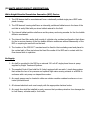
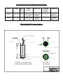
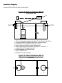
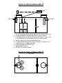
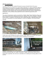
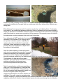
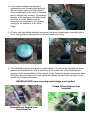
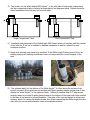
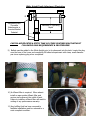
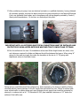
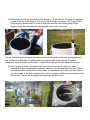
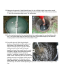
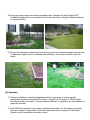
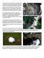
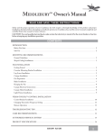
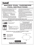
White Knight Microbial Inoculator Generator™ (Patent Pending) Design, Installation, Operation & Service Manual Revised November 2008 © 2008 Knight Treatment Systems, Inc. All Rights Reserved Guardians of Water Quality® 281 County Route 51a, Oswego, NY. 13126 1-800-560-2454 www.knighttreatmentsystems.com TABLE OF CONTENTS I. Introduction to Enhanced Biological Augmentation II. Specifications & Diagrams III. Site Qualification IV. Installation V. Operation VI. Service & Maintenance VII. Forms “We don’t make the onsite treatment systems, We make them better” (I) INTRODUCTION The Enhanced Biological Augmentation of Onsite Wastewater Treatment Systems is the methodology of introducing a group of task specific selected microorganisms though inoculums in tandem with a microbial inoculation generation device that is placed into an onsite wastewater treatment train, typically the septic tank, to significantly improve overall treatment system performance, rehabilitate dysfunctional systems and assure system longevity. The White Knight Microbial Inoculator Generator™ (MIG) continuously inoculates a septic tank or other treatment vessel with naturally occurring selected strains of non-pathogenic bacteria selected for their ability to metabolize organic material. Continuous inoculation is mediated through in-situ cultivation of IOS-500™ inoculumss. Through airlift mixing, recirculation, and fine bubble aeration principles the device brings the selected bacteria into contact with fixed film substrate and the suspended organic compounds in a septic tank, or other process treatment vessel. The introduced cultures of bacteria grow at logarithmic rates as they voraciously digest most of the organic constituents that are found in the wastewater in addition to the organic waste matter that has been transferred to the soil. The fine bubble driven airlift features of the White Knight Microbial Inoculator Generator(MIG) are designed to allow for more efficient transfer of oxygen and low maintenance, high rate circulation of wastewater through the device, and across the fixed film media. An abundant oxygen supply supports the introduced IOS-500™ bacterial cultures providing for more rapid digestion. The tubular configuration internal media is clog resistant and provides for uninterrupted flow across abundant surface area for the establishment of the selected fixed-film culture. Many of the natural bacteria found in wastewater such as the coliform group are not as aggressive at decomposition of the organic constituents found in wastewater and cannot compete with the IOS500™ introduced cultures. The tank serves as the breeding reactor that cultivates and releases the introduced bacteria that are carried by the effluent stream out to the soil enhancing its treatment capabilities and hydraulic functionality. (II) WHITE KNIGHT PRODUCT SPECIFICATIONS: White Knight Microbial Inoculation Generation (MIG) Device: 1. The MIG device shall be manufactured from a rotationally molded single piece HDPE outer plastic housing. 2. The MIG device’s housing shall have an internally partitioned ballast area in the base of the unit that is easily filled with pea stone ballast material in the field. 3. The internal ballast partition shall serve as the primary anchoring member for the fine bubble diffusion mechanism. 4. The internal fixed film media shall consist of a tubular clog resistant configuration that allows for the in service cleaning of the fine bubble diffusion membrane without disassembly of the MIG or requiring its removal from the tank. 5. The location of the IOS-500™ inoculant must be fixed to the inoculating wand and placed in the vertical path of flow just above the fixed film media of the MIG and in contact with the flow stream while in operation. Air Supply: 1. Air shall be provided to the MIG by an external 120-volt AC single-phase linear air pump supplied by Knight Treatment Systems. 2. The supplied Control Panel shall be UL listed, equipped with an audio / visual alarm system that senses the loss of air pressure and optional high water sensing contacts in a NEMA 4x enclosure with a air pump run elapsed time meter. 3. Air supply pumps may be located in either an outdoor weather resistant enclosure or in an indoor protected area. 4. All relevant electrical work must comply with the appropriate electrical codes. 5. Air supply lines shall be installed in such a manner that provides protection from damage due to frost heave, vehicular and/or foot traffic. Model Specifications: Model # BOD loading mg/l/ @ 500 gpd per unit # of Columns per Model Size of Column (dia” x height”) Minimum Air Pipe ID Minimum tank size Approx Diffuser Air Flow (CFM) @ 2 PSI WK-40 up to 750 1 16” x 27.5” ½” 1000 Gal 1.5 WK-78 up to 1500 2 16” x 27.5” ¾” 1500 Gal 3.4 Residential Application Guidelines: 1. Model WK-40: 1 to 4 bedrooms based on minimum 1.5 day residency time of average daily flow within tank. 2. Model WK-78: 5 to 8 bedrooms based on minimum 1.5 day residency time of average daily flow within tank. Institutional & Commercial Application Guidelines: The use of multiple units may be required based on wastewater composition, existing tank size and average daily flow. Consult with Knight Treatment System’s representative for each specific potential application. In general: 1. Institutional Waste Streams: Tank size must allow for minimum of 1.5 days residency time of average daily flow with 2 or more days preferred. (1) Model WK-78 unit per 2000 gallons or less of tank volume and up to 1500 mg/l/day BOD load @ 500 gpd. 2. Commercial Grease Interceptors: Tank size must allow for minimum of 2 days residency time of average daily flow with 3+ preferred. (1) Model WK-78 per 1500 gallons or less of interceptor volume and up to 1500 mg/l/day BOD load @ 500 gpd. Air Supply Specifications: Model # Minimum Maximum Output @ Air Pump 2 psi Sound (CFM) Level @ 3’ Amps Volts WK-40 1.5 32 dBA 1.2 120 WK-78 3.4 36 dBA 2.1 120 UL Listed Alarm/Control Minimum Specifications: Model # Voltage Amps Max Failure sensing Alarm Type Overload protection (amps) Switching WK-40 110 / 120 8 Pressure drop +/or float Visual and Audible 8 Normal/ Silence only WK-78 110 / 120 8 Pressure drop +/or float Visual and Audible 8 Normal/ Silence only White Knight MIG Column Drawing 1" PVC PIPING FIELD ADJUSTED TO HEIGHT 12.00 INSIDE ZIP TIES 1/4" THICK WALL To Air Supply IOS 500 INOCULANT PACKET 27.5" 54x 1" ID TUBULAR MEDIA SECTION 1 US FILTER FLEX DISC FINE BUBBLE DIFFUSER 9IN. DIAMETER SECTION 1 SECTION 2 1.5" DIA. BALAST COMPARTMENT PLUG CUSPATED WRAP PILATED WRAP 10 X 1.50" EQUALLY SPACED 1/2" PVC VERTICAL CROSSECTION SECTION 2 KNIGHT TREATMENT SYSTEMS, INC. 281 COUNTY ROUTE 51A, OSWEGO, NY 13126 WWW.KNIGHTTREATMENTSYSTEMS.COM PROJECT I D: PAGE 1 OF 1 REVI SI ON DATE: SCALE: DRAWING #: DRAWN BY: DJN Installation Diagrams: Important Note: All tanks must be water tight. Typical In Tank Installation WK-40 Cross Section View 1 2 7 3 4 4 INLET OUTLET 8 5 6 1. 2. 3. 4. 5. 120 volt electrical supply through Alarm/Control Panel to Air Pump Air pump installed in weather tight basin, outdoor location ½” ID plastic air supply line from pump location Service risers for monitoring and maintenance White Knight Microbial Inoculator Generator™ Column in 1st compartment of 2 compartment tank. 6. Outlet equipped with Effluent Filter 7. System Alarm Panel 8. IOS-500™ Inoculant Packet Typical In Tank Installation WK-40 Plan View 3 5 4 6 4 Typical In Tank Installation WK-78 Cross Section View 1 2 7 3 4 4 INLET OUTLET 8 5 8 5 6 1. 120 volt electrical supply through Alarm/Control Panel to Air Pump 2. Air pump installed in weather tight basin, outdoor location 3. ¾” ID plastic main air supply line from pump location to tee in riser. ½” ID flexible air line from each side of tee to each column 4. Service risers for monitoring and maintenance 5. (2) White Knight Microbial Inoculator Generator™ Columns in 1st compartment of 2 compartment tank. 6. Outlet equipped with Effluent Filter 7. System Alarm Panel 8. IOS-500™ Inoculant Packets Typical In Tank Installation WK-78 Plan View 3 5 6 4 5 4 Deployment: 1. MIG installation shall only be performed by a Knight Treatment Systems (KTS) trained and authorized provider in conformance with KTS’s guidelines and in compliance with an local regulatory requirements. 2. The MIG shall only be placed in structurally sound watertight septic tanks. The MIG must not be installed in cesspools, block, steel, or other substandard tanks or in any septic tank of volume less than 750 gallons. 3. The septic tank shall provide for a minimum of 1.5 days residency time of the total estimated daily flow of wastewater from the property and in any situation no less than 750 gallons in volume. 4. The outlet of the septic tank must be equipped with an acceptable effluent filter. 5. The septic tank must have acceptable service risers meeting local regulatory requirements to facilitate monitoring and maintenance. 6. In repair situations, a verifiable history of successful performance of the absorption system prior to dysfunction in tandem with a comprehensive site qualification performed by an authorized provider trained by Knight Treatment Systems or a KTS authorized Distributor is required. Service & Warranty: 1. A manufacturer’s component warranty program shall be provided to the property owner for each MIG installed. 2. A comprehensive service program shall be provided to the property owner for each MIG installed. 3. Service of the MIG shall only be conducted by KTS trained and authorized providers in compliance with any local regulatory requirements and at a minimum of 6-month intervals. 4. A minimum initial one-year Operation & Maintenance (O & M) contract shall be provided with each unit installed. 5. A valid O & M contract shall be in place for the life of the MIG. (III) Site Qualification The White Knight Microbial Inoculator Generator’s success is directly linked to the proper determination of the root cause of an onsite system’s dysfunction. In order to determine whether or not the dysfunctional system is a candidate for enhanced biological rehabilitation a thorough site evaluation must be performed. To this end a competent authorized professional must perform a comprehensive site evaluation and owner/operator interview and record search in determining the actual nature of the problem(s) being experienced and to submit the appropriate permit application(s). The system’s infrastructure must be sound and free of defect. Septic Tanks, Distribution Boxes and other components must be evaluated and repaired or replaced if found to be damaged or deficient. All such repairs, if required by local authority, must be performed under an approved repair permit and may be incorporated in the repair application in which the installation of the White Knight is specified. Crushed Pipe Inhibits Flow Corroded D-Box Surface water runoff infiltrating the system will have a major impact on the hydraulic performance and treatment efficiency of the absorption system contributing to its dysfunction. Roof Drains & Driveway Runoff Discharges Up Slope of System Roof Drains flow to Septic Tank access covers in paved driveway Sources of concentrated flow from impermeable areas such as rooftops and driveways must be identified and directed away from system components. Visiting a dysfunctional system during or shortly after a significant rain event can be invaluable tool in assessing the drainage patterns of the property. Inflows from leaky plumbing fixtures place a tremendous burden on the absorption system. Water continuously trickling into the septic tank is a positive sign that either inflow and/or infiltration are taking place. Illicit discharge from sump pumps into the system may also be a contributing factor. Condensate from heating / air conditioning appliances and water softener backwash has been demonstrated to impact the processes of wastewater treatment systems. Conduct an in the home survey of all water using fixtures and any sump pump connections in the presence of the property owner and identify the appropriate corrective measures that would need to be taken. For a dysfunctional OWTS application the physical verification of the existence of a clogging mat is an important evaluation practice. Typically the upslope edge of the leachfield is located with a probe and a small excavation is created in close proximity above the leachfield to a depth below the bottom of the leachfield. Once the initial excavation is made and ground water is not encountered the excavation is moved towards the leachfield’s soil interface to establish the presence of the clogging mat. Typically the internal hydrostatic pressures of the leachfield will breach the clog mat and fill the hole with effluent. The thickness of a clog mat will vary and is dependent upon soil structure and texture. Loose granular soils exhibit a thicker and more pronounced appearance than tighter soils. Depth to ground water and its movement plays a major role in the functionality of a leachfield and its ability to treat wastewater. The hydrology of a lot can be impacted and dramatically change from the time of original system siting due to neighboring development. In such a situation the installation of a swale, curtain or perimeter drain may be a necessity to protect the leachfield from becoming saturated. Consult with the appropriate regulatory authority for direction if ground water impacts are discovered during the site evaluation. (IV) Installation The following components are provided with each White Knight MIG supplied by Knight Treatment Systems: Model WK 40 - (1) Generator Column, H40 Air Pump, Air Pump Housing, (2) IOS-500™ Inoculant Packets, Pressure Sensing Alarm Panel with pump run hour meter, 25’ Alarm Tubing with ½” PVC SCH40 sensing tee, 1st year of component warranty coverage, 1st year of 6-month & 12-month service notifications, (1) IOS-500™ Inoculant Packet shipped at time of 12-month service notification. Model WK 78 - (2) Generator Columns, H80 Air Pump, Air Pump Housing, (4) IOS-500™ Inoculant Packets, Pressure Sensing Alarm Panel with pump run hour meter, 25’ Alarm Tubing with ½” PVC SCH40 sensing tee, 1st year of component warranty coverage, 1st year of 6-month & 12-month service notifications, (2) IOS-500™ Inoculant Packet shipped at time of 12-month service notification. All other components for a complete and proper installation shall be supplied by the installer, which include but are not limited to: Air supply line between air pump and MIG column locations. Air supply line transition fittings, glue, sealants, etc. Electrical supply to Alarm Panel and Air Pump Effluent filter. Replacement tank if necessary. Riser system if necessary. All tools and services required for a complete and proper installation. Important Note: The following directions are provided with the assumption that those involved with the installation of the White Knight Microbial Inoculator Generator hold knowledge of, adhere to, practice and promote the protection of the health and safety of their colleagues, the public and the environment. Becoming educated in and complying with all Industry and OSHA Safety Requirements and governing Regulatory Requirements is the sole responsibility of the installer. Knight Treatment Systems, Inc. assumes no risk or liability for any omissions or actions of the installer or by others associated with the installation. 1) Expose the top of septic tank. The tank must be pumped, visually inspected and ALL solids removed prior to installation of the White Knight™. Tanks and risers must be watertight. Openings, risers, and tank interior must be structurally sound and intact. Septic tanks found to be corrupt must be replaced with a tank that meets local requirements. 2) A riser system meeting local regulatory requirements must be used where absent at the inlet location where the White Knight™ will be installed and at the outlet of the septic tank for effluent filter servicing. The minimum diameter of the opening for the White Knight should be 20 inches. Caution must be exercised in the modification of an existing opening for the installation of the White Knight. 3) All risers must be installed watertight and extend just above finished grade. Lids shall conform to any local regulatory requirements and prevent unauthorized entry. 4) The Leachfield must also be drained of ponded effluent. This can be accomplished via access gained at the Distribution Box and by excavating at the lowest point of the Leachfield and pumping out the ponded effluent. Where absent, Knight Treatment Systems recommends that a Distribution Box Access Riser and Cover system be installed, be water tight and allows for the monitoring of system performance. IMPORTANT NOTE: Lines containing settled sludge must be jetted. Ponded Effluent Removal from Leachfield Ponded Effluent Removal from Distribution Box 5) The location for the White Knight MIG Column™ is the inlet side of both single compartment and two-compartment tanks, centered as illustrated by the diagrams below. Column should be placed equidistant from the near end and side walls. White Knight Column Centered Single Compartment Tank Dual Compartment Tank 6) Installation and placement of the White Knight MIG Column must not interfere with the function of the inlet tee. If the tee is modified to facilitate installation it must be restored to code compliant condition. 7) Septic tank openings may need to be modified. If the White Knight Column cannot fit into an existing opening any opening modification must not compromise the overall integrity of the tank. 8) The optimum depth for the bottom of the White Knight™ is 4 feet below the surface of the liquid in the tank. When tanks are encountered with liquid operating depths greater than 5 feet elevate the White Knight™ to the optimum depth. Utilizing 6 stainless steel 1.5“ long screws securely fasten an inverted 5-gallon plastic bucket to the bottom of the tower with holes created in the base of the bucket to prevent floatation. Trim sides of the inverted bucket to achieve the optimum depth. For tanks with depths greater than 6 feet suspending the White Knight from the riser with non-corrosive attachments is also an acceptable practice. White Knight Depth Adjustment Illustration Suspending NonCorrosive Attachments or Inverted Bucket Pedestal Maximum 5’ Operating Depth CAUTON: NEVER ENTER A SEPTIC TANK OR OTHER CONFINED SPACE WITHOUT FOLLOWING OHSA REQUIREMENTS & PROCEEDURES! 9) Ballast must be added to the White Knight prior to its placement into the tank. Locate the plug near the base of the tower and completely fill ballast compartment with clean, small diameter pea stone replacing plug when completed. 10) A effluent filter is required. When absent install an appropriate effluent filter and service riser system at the outlet of tank. Failure to install an effluent filter will result in voiding of any performance warranty. 11) Any baffling that has been removed to facilitate installation must be returned to a code compliant condition. 12) The locations for the Alarm Panel and Air Pump Basin should facilitate running of airline to the White Knight riser and the related electrical connections for the panel and air pump. The location should shield the basin from direct sunlight and weather events in so much as possible. Air Pump Basins should be slightly elevated when flooding is a possibility and always placed on a 2” bed of washed gravel to facilitate drainage. Drill airline entry hole in bottom of basin over sizing the penetration to allow for the drainage of any water that may find its way into the basin. 13)A trench must be provided for the air supply line between the Air Pump location and the White Knight service riser. Excavation may be accomplished by either hand or with the use of power equipment. Trench should uniformly slope from the air pump location to the service riser to prevent any airline condensate from pooling. When performing an excavation make sure you are in compliance with local procedure and safety practices with regard to the protection of underground utilities. NOTE: Where an airline must cross vehicle traffic or parking areas such as a driveway the air supply line should be protected by placing it in a sleeve such as a 1” ID Schedule 80 PVC pipe installed a minimum of 12” below the surface of the traffic area. 14. The air supply line can be either Schedule 40 PVC or HDPE piping, ½” ID minimum for White Knight Model WK-40, ¾” for White Knight Model WK-78. HDPE piping is recommended as it reduces the amount of connections to be made minimizing the potential for air leaks. 15. Place a 2” x 8” x 16” cinder or patio block in basin as a base for the Air Pump. Install airline through bottom of basin. Install the pressure-sensing tap near the Air Pump into the airline making the appropriate transitions in making connections. 16. Indoor air pump locations may create service complications due to lack of accessibility during property owner or tenant absences and should be avoided if possible. When indoor installation is necessary, locate indoor air pumps in an easily accessible area of the building’s basement, a garage or a utility room on a stable base. 17. After positioning air pump, have an electrical contractor or qualified electrician, having obtained all necessary permits; connect the alarm panel and air pump according to the National Electrical Code, any applicable local codes, and in compliance with wiring diagram provided by Control / Alarm panel manufacturer. Do not turn on electricity at this point. IMPORTANT NOTE: ALL EXTERIOR ELECTRICAL CONNECTIONS MUST BE INSTALLED AND PROTECTED BY NEMA LISTED EXTERIOR WEATHER TIGHT CONDUIT AND FITTINGS. 18. Run the airline into the riser. On installations where two White Knight towers are used, a tee and valves are required to divide and balance the airflow between the towers. When using ¾” piping for the main air supply line make the transition at the tee to ½” ID piping with adjustment valves to feed each tower. Piping and any manifolds should be configured so, that if necessary, the tower is capable of being removed without causing damage to the air supply line that enters the riser. Where an airline must cross vehicle traffic or parking areas such as a driveway the air supply line should be protected by placing it in a sleeve such as a 1” ID Schedule 80 PVC pipe installed a minimum of 12” below the surface of the traffic area. 19. White Knight towers are manufactured to receive ½” ID Schedule 40 PVC pipe. A coupling is located at the top of the tower to one side for the air supply connection. PVC Solvent Weld Primer must be applied and PVC Solvent Weld Glue must be used. When gluing fittings together slowly twist the assembled components until a “set” can be felt. The use of flexible piping between the tower and air line entry point in the riser is acceptable and may facilitate the placement of multiple towers through a single access opening. Threaded connections must be airtight and the use of a liquid Teflon pipe joint compound should be used. 20. With a length of airline connected to the tower lower the tower into place. For deep installations in may be necessary to place an extension onto the supplied lifting rope. Make sure that the unit is resting level on the bottom if a pedestal is used, stable and centered as close as possible in the tank compartment in which it is being installed but accessible from the service riser. Connect the air supply lines and secure the lift out line. 21. Activate the air pump and with the White Knight tower in place and refill the tank to normal operating level with clean water. Caution must be exercised for properties served by a well with regard to depleting the water supply. Always attain property owner permission to make use of their water supply. In situations where there is questionable well capacity water should be brought in to refill the tank. DO NOT REFILL TANK WITH SEPTAGE FROM PUMPER TRUCK. 22. The IOS-500™ is placed into the system via a 1” PVC wand shipped with the unit that must be assembled. Wand Assembly The wand is then inserted into the center of the tower’s tubular media with the IOS-500™ inoculant packet affixed to the “Tee” side of the coupling with the supplied plastic cable ties. The coupling serves a dual purpose, as a stop to prevent the tapered end of the wand from coming into contact with the fine bubble diffuser located beneath and the method to attach the upper portion of the wand. The upper portion serves as the point of attachment for the IOS-500™ inoculating packet and is provided with a “Tee” fitting which facilitates wand placement, removal and allows for maximum circulation of the air lifted effluent throughout the tank. The IOS-500™ inoculant must not be put into place until the system is active and the liquid level in the tank provides at least 2 ½” of cover over the top of the tower. 23. Determine the amount of liquid that will cover the top of White Knight tower under normal operating conditions and adjust the inoculating wand so that the “Tee” of the wand protrudes 2” above the normal operating level of the wastewater. 24. Fix the inoculant packet to the wand just above the coupling using the provided plastic cable ties. Trim tie ends and insert the wand into the center of the White Knight up flow until the coupling makes contact with the top of the tubular media. 25. The airlift action of White Knight should display a rolling robust circulation pattern at the surface of the liquid above the tower without noticeable glugs or gurgles. Visible bubbles should be very small in size and typically no larger than a small pea. An erratic flow pattern, larger size bubbles and unusual sounds are indicators that an air leak is present or something is caught in the tower’s media column interfering with the upward flow pattern and must be corrected. Debris may be cleared by inserting a ½” diameter pole or ridged plastic tube, with sharp edges broken, down through the tubular media repeating the process several times until the blockage breaks free. 26. Secure all access covers and restore excavated areas. Complete the White Knight MIG™ Installation Registration Form provided with the unit returning it to Knight Treatment Systems in a prompt fashion. 27. Areas of the absorption system that had broken out and have untreated sewage exposed must be addressed. Apply lime to the affected area followed by a thin layer of topsoil, seed and mulch. (V) Operation: 1) Following installation, operational guidelines and the requirement of routine periodic maintenance must be reviewed with the Owner / Operator of the system. A “White Knight Microbial Inoculator Generator™ Owners-Operators Manual” is supplied by the manufacturer to assist with this task. 2) Each OWTS will develop its own unique operational personality over time based on operator input and change of usage patterns. Periodic adjustments may be required of the OwnerOperator as the operational personality evolves. (VI) Service & Maintenance 1) Routine residential service is conducted every 6 months through a maintenance contract with a KTS authorized provider. Commercial / Institutional system requirements will vary and must be tailored for each specific application. However, approximately two weeks following the White Knight installation a follow up visit must be conducted by the installer and reinoculation performed. The second IOS-500™ inoculant packet that was shipped with the White Knight is used for this purpose. Knight Treatment Systems, Inc. will notify each system’s registered service provider 30 days in advance of a normal service visit. Following installation, routine service must be conducted at the scheduled intervals with reinoculation occurring annually. 2) Upon removal of the wand the packet should exhibit brownish colored biofilm. This biofilm may also form on other system components. The bubble pattern should be robust and rolling, as it was when the unit was first activated. 3) Wearing proper personal protection equipment, remove the old inoculant packet from the wand, open the packet and empty its contents back into the tank. Do not throw the used inoculant sack back into the tank. Place the sack and the removed zip ties into empty the plastic bag that the replacement packet came in, carefully seal the bag and place this into another suitable container and dispose of with household trash. Affix new inoculant packet to the wand and reinsert the wand into the White Knight tower. 4) Effluent removed from the flow stream of the White Knight and placed into a clear container should be translucent and light in color with an appearance similar to that of “Lemon Aid” with no offensive odor. 5) As part of each service visit a ½” diameter pole or ridged plastic tube with sharp edges removed should be inserted down through the media column of the tower and the diffuser membrane gently bumped several times while in operation. Biofilm sometimes form on the membrane, which could reduce fine bubble production if allowed to build up. “Bumping” the diffuser breaks free any biofilm. 6) The effluent filter must also be checked. It should appear relatively free of undigested organic materials and will typically have light brownish biofilm on it. Inorganic materials should be removed and disposed of properly. Do not remove the beneficial biofilm. 7) Should extraordinary amounts of foaming be encountered it is typically caused by the over use of detergents or the use of high sudsing formulations. Spraying the foam with water from a garden hose will knock down the suds so that the system can be maintained. 8) Infrequent foaming events will not have a major impact on the overall performance of the White Knight but can cause nuisance concerns and trouble calls should the foaming become visible. The user must be made aware of the situation and corrective actions implemented. 9) The air pump’s air filter must be removed and cleaned annually unless unusual dust conditions exist. The foam filter is easily cleaned by washing in a mild soap and water solution, rinsed and allowed to dry. Cleaning and rinse water should be disposed of at the inlet side of the tank. 10) The Absorption System should be inspected for sign of any breakout and its condition duly noted. 11) If present, Distribution Box Riser(s) should be opened and the depth of any liquid within the Distribution Box recorded. Observe personal protection procedures and clean the measuring instruments with a disinfectant immediately following use. 12) Complete the Service Visit Report. Leave a copy with the client and file appropriately. (VII) Forms White Knight MIG™ Site Evaluation Form Owner / Operator Interview: Property usage Single Family Residential____ Multi Family Residential____ Commercial/Institutional______ Type of enterprise________________________________ How long has property been occupied? ____ years # Bedrooms ____ # Tubs/Showers ____ Hot tub, spa, whirlpool bath? Garbage Disposal Unit? Y Food Service? Y Y N N N Number of Meals Per Day____ Commercial Dish Washer? Y N Grease Trap / Interceptor? Y N Size____________ Water Supply? Water Meter? Y Well Municipal N If yes average daily flow___________ If well, does a water purification/softener backwash discharge into septic system? Y N Does the property have a sump pump? Y N Y N Laundry discharge into septic system? N Y Discharge into septic system? Laundry detergent? Liquid Powder Describe Laundry & Cleaning Habits (products used and how often): _________________________________________________________________________________ _________________________________________________________________________________ _________________________________________________________________________________ Has property usage expanded since installation of original septic system Has usage of property changed since installation of original septic system? Y N Y N If yes, describe changes. ______________________________________________________ Trouble Symptoms Drain back-up ___ Visible effluent ____ Evidence of Previous Breakout ______ Lush vegetation ____ High tank level ____ Liquid Level in Tank Above Outlet Invert _________ Odor ____ Frequent Pumping ___ Other ____________________________________ Septic System Type of System __________________________________________________________________ (Cesspool, tank and leach field, other) Age of system ___________ Plan available Y N Date last pumped ___________ Attach copy of record of pumping, if available Septic tank size __________ Tank Material Pump chamber Y N Distribution box Concrete Plastic Metal Y N Unkown Leachfield type & size Pipe/stone___ Plastic Chambers___ Concrete Chambers___ Seepage Pit___ Other (specify) __________________________________________________________________ Prior attempts to fix system Y N If yes, what and when _______________________________ _________________________________________________________________________________ _________________________________________________________________________________ _________________________________________________________________________________ Permit numbers for prior repair work performed ___________________________________________ Site Investigation: Time and Date ofSite Visit: _________________________________________________________ Septic tank size __________ Tank Material ___________ Tank Condition (observed following pumping) ____________________ Inlet Access Y N Center Access Y N Discharge Access Y N Date of Pump Out & Name of Pumper _________________________________________________ Depth of tank from inside bottom to outlet invert ________ Depth of soil cover over tank _________ Baffle condition ____________ Discharge effluent level ______" above outlet invert Septic Tank Discharge pipe description___________________________________________________ Grease Interceptor Size __________ Tank Material ___________ Tank Condition (observed following pumping) ____________________ Inlet Access Y N Center Access Y N Discharge Access Y N Date of Pump Out & Name of Pumper _________________________________________________ Depth of tank from inside bottom to outlet invert ________ Depth of soil cover over tank _________ Baffle condition ____________ Discharge effluent level ______" above outlet invert Grease Interceptor Discharge pipe description_____________________________________________ Ponded Effluent level in leach field/trenches ________ Biological clogging confirmed Y N (If yes, attach photo) Soil Type & Description _______________________________________________________________ (Attach photo) Observed Depth to Ground Water ____________ Storm Water / Snow Melt Infiltration? Y N Apparent structural damage or other unusual findings_______________________________________ (Attach photo) __________________________________________________________________________________ Provide sketch of system layout and cross section of absorption system below. Please indicate all breakout points, boundaries and depth of ponded effluent within system. Installation Requirements: Length of airline run ________ft Jet Lines: Y N Length of electrical run ______ft RIDEM Approved Effluent Filter (circle one): In Place / Must be Installed Tank(s) requires service riser(s) & covers? Y Tank(s) require replacement? Y Additional tanks required? Y N N N Depth of tank top from finished grade ______in. Need _________in. of riser Distribution Box requires service riser & cover? Y N Box is: Concrete___ Plastic____ Size ____ Depth of D-Box top from finished grade ______in. Need _________in. of riser Distribution line or other modifications needed: ________________________________________________________________________________ ________________________________________________________________________________ Does System qualify for White Knight? Y N Additional Repair Permits Required? Y N Additional Comments: Evaluation Performed By: _____________________________________ White Knight Microbial Inoculator/Generator™ Service Visit Record Owner Name__________________________ Unit Serial Number ______________ Date Visited ______________________ Field Technician ____________________ Purpose of Visit ___ Routine Maintenance ___Customer Concern ___ 2 Week Spot Check Tank Liquid appearance: ___Translucent ___Clear ___Other (specify)_________________________ Liquid odor: ___ None __ Perfumed ___ Noxious ___ Other (specify)________________ Bubble Pattern: ___Normal ___Abnormal (describe) _______________________________ Unusual observations: ____________________________________________________________ Effluent Filter: ___ In Place ___ Housing to outlet pipe secure ___ Cleaned ___ Hair / Lint buildup Notes: _______________________________________________________________________ White Knight: ___ Biological Growth Visible ______________ Color ___ Ample flow through unit ___ Unit Clogged with ______________ ___ Inoculant replaced ___ Unit removed & cleaned Notes: ______________________________________________________________________ ____________________________________________________________________________ ____________________________________________________________________________ Air Supply & Control Panel Location: Outdoor ____ Indoor ____ Hour Meter Reading ________________________ ___ Pump Operating Properly ___ Air Filter Clean ___ Alarm Operating Properly Notes: _______________________________________________________________________ Soil Absorption System Weather: Precipitation previous 48 hrs ________ Surface Condition: Time of inspection ____________________ ____ Dry & Firm ____ Soft & Spongy ____ Saturated _____ Breakout / Location(s) ________________________ Distribution Box accessibility via Riser to grade: ____ Yes _____ No If yes ____ inches static water above outlet inverts. Notes: _______________________________________________________________________ _____________________________________________________________________________ _____________________________________________________________________________ Repairs or Modifications Performed: _________________________________________________________________________________________ _________________________________________________________________________________________ _________________________________________________________________________________________ Additional Comments: __________________________________________________________________________________ __________________________________________________________________________________ __________________________________________________________________________________ __________________________________________________________________________________ ______ Service Visit Report Left With Property Owner Technician's Signature ____________________________________________