1
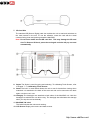
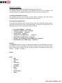
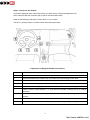
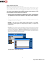
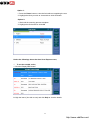
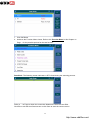
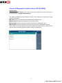
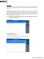
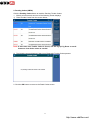
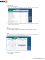
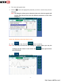
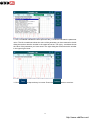
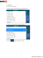
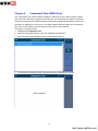
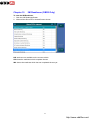
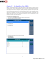
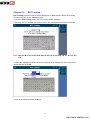
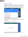
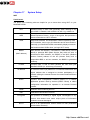
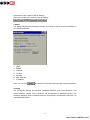
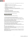
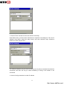
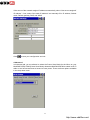
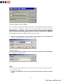
Safety Precautions and Warnings
To prevent personal injury or damage to vehicles and/or the MaxiDAS, read this
instruction manual first and observe the following safety precautions at a
minimum whenever working on a vehicle:
l
Always keep attentive while driving.
l
Always perform testing or repairing in a safe environment. Wear safety eye
protection that meets ANSI standards.
l
Keep clothing, hair, hands, tools, test equipments, etc. away from all moving or
hot engine parts.
l
Operate the vehicle in a well ventilated work area. Exhaust gases are poisonous.
l
Put blocks in front of the drive wheels and never leave the vehicle unattended
while testing or repairing.
l
Use extreme caution when working around the ignition coil, distributor cap,
ignition wires and spark plugs. These components create hazardous voltages
when the engine is running.
l
Keep a fire extinguisher suitable for gasoline/chemical/electrical fires nearby.
l
Put the transmission in PARK (for automatic transmission) or NEUTRAL (for
manual transmission) and make sure the parking brake is engaged.
l
Refer to the user’s manual for the vehicle being serviced and adhere to all
diagnostic procedures and precautions. Otherwise personal injury or unneeded
repairs may result.
l
DO NOT mount the MaxiDAS in a position which can obstruct the view of the
driver.
l
DO NOT use the MaxiDAS and drive the vehicle at the same time. Any
distractions may cause an accident.
l
DO NOT mount the MaxiDAS in a position which could cause it to be propelled
through the vehicle during an accident causing injury, such as over or near an
airbag.
l
DO NOT route the cable in a position which would interfere with the operation of
the vehicle controls.
l
DO NOT connect or disconnect any test equipment while the ignition is on or the
engine is running. Failure to so could result in control unit damage.
l
Keep the MaxiDAS dry, clean, free from oil/water or grease. Use a mild detergent
on a clean cloth to clean the outside of the MaxiDAS when necessary.
1
http://www.obd2be.com/
Chapter 1 Using This Manual
Congratulations on purchasing the MaxiDAS 708!
1. Conventions
ü Note
Provide helpful information such as additional explanations and tips.
Example:
Note: Do not force the SD card into the card slot. This may damage the card slot.
ü Important
Suggest you to avoid the situation which may result in damage to the unit or vehicle.
Example:
Important: Free Frame data and manufacturer enhanced data and codes from the vehicle’s
on- board computer will be erased once you confirm to erase Trouble Codes. (Free Frame
data PIDs are information used to help the technician verify the condition at the time a fault
is set.) Further, the I/M Readiness Monitor Status, for all vehicle monitors, is reset to INC
(Incomplete) status.
ü Possible
Provide the description for the screen which might appear on the scan tool.
Example:
Possible 1: For some of the vehicle, identify vehicle process is not needed. Component test screen
appear at this stage already and allows you to perform the component test.
Possible 2: For the others, continue selecting the vehicle from the scan tool is needed. To identify
the vehicle, you may need to complete a series of selections, which may include any of the
followings.
(Benz as an example) Select one of the attributes from each screen and highlight the
attribute to enter to the next page. The screens continue appearing until the selecting process
complete.
ü Option
Provide the description for the options which are available
Example:
Option 1:
1. Press the Pause button to view the fault without completing the test.
2. Highlight the fault you wish to view and then click OK button.
Option 2:
1. Wait until the scanning process complete.
2. Highlight the fault and then click OK.
2
http://www.obd2be.com/
Bold Text
Used to emphasis the selectable items such as buttons and menu options.
Example:
Click OK to save the change, or click Cancel to exit without save changes.
2. Symbols
ü ( )
Indicates vehicle which used as an example in the chapter.
Example:
Chapter 5
Auto Scan (HONDA)
Note: The chapters show in this manual are only the possible options. During
testing, only the options available for the vehicle and ECU being tested will
appear on screen of the scan tool.
ü < >
Indicates those vehicles who are able to use the specially function show in the following
chapter.
Chapter 12
On- Board Mon. Test <OBDII>
3
http://www.obd2be.com/
Chapter 2 General Information
Introduction
1. Icon Description
The table below gives brief description of the control button on this software.
Name
Button
Description
Page Down
Used to scroll through the text and data
Page Up
Used to scroll through the text and data
Data
Logging
Allows you to record the useful data when problems occurred
to your vehicle. These data assists the engineer in updating
the MaxiDAS 708 Software. Refer to Notice the followings
about the MaxiDAS Screen Icon on Page 5 for details.
Snapshot
Used to return to the main menu of the MaxiDAS.
Home
Page
Allows you to save the picture of current screen to the
memory card.
WIFI
The shortcut that allows you to change the internet setting, it
is also a Signal Strength icon shows your current signal
strength. More lines indicate more signal strength. Five lines
indicate maximum strength, and one line indicates least
strength.
Internet
Open a webpage
4
http://www.obd2be.com/
Notice the followings about the MaxiDAS Screen Icon,
1. Data logging
The Data logging function is used to report the problem that cannot be detected or solved
by the MaxiDAS 708. To perform a data logging, follow the instruction below to operate the
data logging while the vehicle is being scan. The error report will be sent to the technical
support center automatically. The engineer will try to solve the problem and get back to
you within 48 hours with the update function. You can finally upgrade your MaxiDAS 708.
Note: The following picture shows the process of the data logging.
1. Click the Data logging button from the toolbar.
2. The following dialog box shows.
3. Click the Start Logging button and use the information box for extra information.
5
http://www.obd2be.com/
4. The pervious error report record appears in the History Report Manage box.
5. To delete one of the history reports, highlight the history report as you desire and click
Del Select button at History Report Manage.
6. Optionally, click Del All button at History Report Manage to delete all of the history
report.
2. Screen with Virtual Keyboard
Virtual Keyboard
You can touch or click a key on the screen viewable keyboard, the chosen character will
be written to the place of the cursor. It allows you to input text for the information you
desired.
1. Drag the virtual keyboard with stylus to relocate.
2. Use the keyboard to fill in the dialog box with all the information as desired.
Press UP/ Down button to change value.
Press Left/ Right button to change character.
Press ? To view help information on the screen or to exit help menu.
3. Select OK to finish and close the Dialog Box.
Note: The new item now appears on the list and is highlighted
Drop-down dialog box
Optionally, use the drop-down dialog box to find the item as desired if there is a previous
record. Highlight the item as desired. Select OK to finish and close the Dialog Box.
3. Scanner Layout
Location – Displays on top of the screen to assist you to identify the component location.
Main menu - The main menu displays in the left-hand panel of the screen.
The following sections are detailed below:
6
http://www.obd2be.com/
Highlight one of the following sections (USA, European and Asian) and you will find a
screen lists all available vehicle manufacturers. These Items are shown in the order in
which they were entered. For example, the vehicle manufacturer you choose more often
will display in the front, while those which used less or never used will be displayed at the
end.
7
http://www.obd2be.com/
Component Descriptions
1. Main Connection Port Connect to the mains for power supply of updating, printing
data logging and internet access after disconnecting from the vehicle.
2. USB Connection Port Connect to the computer for updating and printing.
3. Diagnostic Socket Provides power supply and connection to the vehicle via
diagnostic cables and connectors supplied.
4. Internet Connection Port Provides internet access for updating, printing and data
logging and brings the internet resource of your choice at your fingertips.
5. ON/ OFF Button Powers on/ off the diagnostic tool.
Note: The scan tool will not turn off automatically; it stays on until you turn it off.
6. LED Indicators
The three light-emitting diodes indicate certain system conditions,
Communication LED – Green LED light in middle shows when the unit is in service.
Wireless LAN activity LED – Green LED light in the left shows when a wireless local
area network in enabled, flashes when data is being sent or received.
Main Power LED – Red LED light in the right shows when the unit is powered on.
8
http://www.obd2be.com/
7. SD Card Slot
The standard SD (Secure Digital) card slot enables the unit to read and write data to
the card inserted in the slot. To use the software, insert the card with the metal
contacts facing down and pointing toward the MaxiDAS.
Note: Do not force media into the SD card slot. This may damage the SD card
slot. To Remove SD Card, press the card again and slot will pop out card
automatically.
8. Stylus The Stylus is used for typing and selecting. To calibrating Touch Screen, refer
to chapter 7 – 8, Calibrating Touch Screen.
9. Stand The built- in metal stand allows the unit to rest for hands-free viewing when
extended. It is attached to the back of the scan tool and can be secured to the back
again unit when not in use.
10. Handgrip The handgrips are attached to both sides of the MaxiDAS unit. Hold the
handgrips to stabilize the unit while using. The handgrip also eliminates the damage
when you drop the tool accidentally.
11. MaxiDAS 708 Label
The Label includes the notice and warning.
12. LCD Screen Displays the menus and data screens.
9
http://www.obd2be.com/
Important: Use the supplied stylus or plastic-tipped pens for touch screen
display. Do not use pencil, pen or any sharp object on touch screen
display.
13. Memory Card
The Memory Card contains the tool’s diagnostic software, applications and maximum
of 4 Gigabytes storage.
Note: Do not remove the memory card while the unit is in service.
14. DLC Cables
The DLC (Data Link Connector) Cable is used to connect between the scan tool and
vehicle’s DLC. Numbers of cables are provided; select the appropriate one for the
vehicle being tested. An optional extension cable may also be used.
15. AC Power Supply
The AC power supply and power cord (12V and 3.33A) is used to power the scan tool
from wall socket.
10
http://www.obd2be.com/
Software Descriptions
This section shows the software which is currently used for the tool.
The MaxiDAS software is provided on a SD Memory card and can be updated. Free
software updates are available periodically on the Internet at www. maxidas.com.
1. Software Applications Overview
The software has two main features: perform vehicle component test and provide
information that may assist you in understanding the component.
Scan Diagnostic Applications
To perform scan diagnostic tests, identify a vehicle you wish to test from the main screen.
Following the instruction on each screen that appear to access to the function test. The
diagnostic functions varies depend on the type of vehicle.
ü
ü
ü
ü
ü
ü
ü
ü
Auto Scan (HONDA) … Chapter 5
Diagnostic Trouble Codes…Chapter6
Live Data (OBDII) …Chapter 7
Freeze Frame …Chapter 8
Component Test(OBDII Only) … Chapter 9
I/M Readiness (OBDII Only)… Chapter10
O2 Mon. Test ( O2 Monitor Test)( OBDII Only)…Chapter11
On-Board Mon. Test (OBDII Only) …Chapter 12
Playback
The Playback function is used for reviewing saved data files. The data files are saved to
the Maxidas’s memory card with the data stream saving function, DTC saving function,
freeze frame saving function and the automated testing and diagnostic system. See
Chapter … at Page …for details
Update
Setup
ü
ü
ü
ü
ü
ü
ü
ü
ü
ü
WIFI
Network
Unit
Date/Time
Language
Backlight
Beep
Touch
Remote desk
About
11
http://www.obd2be.com/
Chapter 3
Setup
Step 1: Insert the Memory Card
Make sure the SD Memory Card is inserted properly into the MaxiDAS card slot.
1. Insert the SD memory card with the metal contacts facing down and pointing toward
the tool.
2. Remove the card and insert it again if the SD card is not mounting properly.
Note: Do not force the SD card into the card slot. This may damage the card
slot.
Step 2: Connect the Hardware Model& Power Supply
To provide power to this unit, use an external power supply or simply connect this unit to a
vehicle with a communication cable. Press the power button once and wait until the
system boots up. After a brief moment, the MaxiDAS Diagnostic Platform displays and the
tool is now ready to operate. See Chapter 4 on page 10 to assist you to find the DLC on
your vehicle.
Note: The scan tool does not have a battery and can not be charged, make sure
the unit is connected to a power supply before using the scan tool.
12
http://www.obd2be.com/
Chapter 4
Scan Diagnostics Applications
Overview
To perform scan diagnostic tests, you have to connect the scan tool to a vehicle’s data link
connector with a communication cable firstly. Then identify a vehicle you wish to test from
the main screen. Following the instruction on each screen that appear to access to the
function test. The diagnostic functions may include any of the followings,
ü
ü
ü
ü
ü
ü
ü
ü
ü
ü
ü
Auto Scan (HONDA) … Chapter 5
Diagnostic Trouble Codes…Chapter6
Live Data (OBDII) …Chapter 7
Freeze Frame …Chapter 8
Component Test(OBDII Only) … Chapter 9
I/M Readiness (OBDII Only)… Chapter10
O2 Mon. Test ( O2 Monitor Test)( OBDII Only)…Chapter11
On-Board Mon. Test (OBDII Only) …Chapter 12
Vehicle Info …Chapter 13
DTC Lookup …Chapter 14
Playback … Chapter 15
For short description of the diagnostic function, see Step 3: Diagnose the vehicle in this
chapter.
13
http://www.obd2be.com/
Step 1: Connect to the Vehicle
To perform diagnostic tests, select the vehicle you want to test, connect the diagnostic tool
to the vehicle’s data link connector (DLC) with a communication cable.
Refer to the following instruction to locate DLC on your vehicle.
The DLC is usually located 12 inches under instrument panel dash.
Explanation of Diagram Numbered Locations
Location
Description
1
Underneath dashboard, under the steering
2
Underneath dashboard, between the driver-side door and steering column area
3
Underneath dashboard, between the steering column area and the center console
4
Dashboard instrument/gauge area, between the steering column and center console
5
Dashboard instrument/gauge area, between the driver-side door and steering column
6
Center console, vertical surface ( i.e., near radio and climate controls), left of/ on vehicle
centerline
7
Center console, vertical surface right of vehicle centerline or on passenger side of center
console.
8
Center console, horizontal surface (i.e., armrest, handbrake area), in front passenger area
9
Any location other than locations 1-8 ( i.e., passenger area, passenger side glove box)
14
http://www.obd2be.com/
Step 2: Identifying the Vehicle
Option 1: Select manually from the main menu,
The following messages only show some of the possible options. During testing, only the
options available for the vehicle and ECU being tested will appear on the screen. Select
one of the attributes from each screen and highlight the attribute to enter to the next page.
The screens continue appearing until the selecting complete. Follow instruction on each
screen that appears to find the access to the function test.
1. Select the group of the manufacturer by highlighting menu option. The manufacturers
are categorized into three groups according to the locations (USA, European or
Asian).
2. Press the manufacturer key to enter a new screen. A dialog box pops up shows the
loading process, wait until compete.
Possible 1: For some of the vehicle, identify vehicle process is not needed.
Component test screen appear at this stage already and allows you to perform the
component test.
Possible 2: For the others, continue selecting the vehicle from the scan tool is needed.
To identify the vehicle, you may need to complete a series of selections, which may
include any of the followings. (Benz as an example) Select one of the attributes from
each screen and highlight the attribute to enter to the next page. The screens continue
appearing until the selecting process complete.
(All Model Series, 169 have been selected)
15
http://www.obd2be.com/
(As of 12/2005, Left hand steering have been selected)
(Sedan and Gasoline have been selected)
(167.031 A 150 has been selected and the communication screen shows)
16
http://www.obd2be.com/
Option 2: Select form the Vehicle Record (If the vehicle has Auto Scan function)
To identify a vehicle by vehicle record,
1. Click the Vehicle Record button.
2. Select the Vehicle ID from the list.
Note: This option is only available to those which have Auto Scan function, refer
to Chapter 5 Auto Scan (HONDA) on Page 23 for how to establish a vehicle
record access.
3.
The following screen displays and asks for your confirmation, click Yes to select or
click No to exit.
4.
The following screen shows the communication status.
17
http://www.obd2be.com/
5. The Information screen shows and asks you to input correct ODO value. Use the
virtual keyboard to enter.
1) Drag the virtual keyboard with stylus to relocate.
2) Use the keyboard to fill in the dialog box with all the information as desired.
3) Select OK to finish and close the dialog box.
Optionally, use the drop-down dialog box to find the vehicle if the previous recode is
available.
Option 3: Select by OBD II Quick Test
OBDII/ EOBD is used to provide a quick test for the users, in this section, the vehicle can
be tested directly without completing the vehicle identification process.
18
http://www.obd2be.com/
Step 3: Diagnose the vehicle
During testing, only the options available for the vehicle and ECU being tested will appear
on the screen. The diagnostic functions may cover any of the followings, read the screen
and chose one of the options to perform a test.
ü
Auto Scan
The Auto Scan does an automatic test of the ECU being tested and then displays
a summary of the test results. From the summary, you can access to the
Function menu (Refer to 26) and view detailed test results, such as DTC
descriptions and related repair information. To see the details, refer to Chapter 5
on page …
ü
Diagnostic Trouble Codes
This is a shortcut that allows you to quickly access vehicle systems without
completing a Vehicle ID, so as to find out what repairs are needed. Also refer to
Chapter 6 for details on page…
ü
Live Data
The Live Data function allows you to view the live (real time) PID data from the
vehicle’s computer module. For details, refer to Chapter 7 on page
ü
Freeze Frame
The Freeze Fame function allows you view DataStream “Snapshots” that were
automatically recorded by the ECU when one or more DTCs occurred. By
viewing the actual data values from the time of a fault, you may be able to
determine what caused the fault. For details, refer to Chapter 8 on page.
ü
Component Test
The Component Test function allows initiating a leak test for the vehicle’s EVAP
system. The scan tool itself does not perform the leak test, but commands the
vehicle’s on-board computer to start the test. Different vehicle manufacturers
might have different criteria and methods for stopping the test once it has been
started. Before starting the Component Test, refer to the vehicle service manual
for instructions to stop the test. For details, refer to Chapter 9 on page.
ü
I/M Readiness
Refer to Chapter 10 on page… for detail.
ü
O2 Mon. Test ( O2 Monitor Test)
OBD II regulations set by the SAE require that relevant vehicles monitor and test
the oxygen (O2) sensors to indentify problems related to fuel efficiency and
vehicle emissions. These tests are not on- demand tests and they are done
automatically when engine operating conditions are within specified limits. These
test results are saved in the on-boards computer’s memory. For details, refer to
19
http://www.obd2be.com/
Chapter 11 on page…
ü
On-Board Mon. Test
The on – Board Monitor Test is useful after servicing or after erasing a vehicle’s
control module memory. The On- Board Monitor Test for non- CAN- equipped
vehicles retrieves and displays test results for emission- related powertrain
components and systems that are not continuously monitored. The On- Board
Monitor Test for CAN- equipped vehicles retrieves and displays test results for
emission-related powertrain components and systems that are and are not
continuously monitored. Test and component IDs are determined by the vehicle
manufacturer. For details, refer to Chapter 12 on page… details.
ü
Vehicle Info
The Vehicle Info. enables retrieval of Vehicle Identification No. (VIN), Calibration
ID Nos. (CINs), Calibration Verification Nos. (CVNs) and In-use Performance
Tracking on 2000 and newer vehicles that support Mode. To see the details, refer
to Chapter 13 on page …
ü
DTC Lookup
DTC Lookup function is used to search definitions of. DTC stored in built-in DTC
library. To search the DTC by the Lookup function, refer to Chapter 14 on
page …
ü
Playback
The Playback function is used for reviewing saved data files. The data files are
saved to the MaxiDAS’s memory card with the data stream saving function, DTC
saving function, freeze frame saving function and the automated testing and
diagnostic system. The Playback function also allows you delete recorded data
files and allows you copy saved data files to and from a portable USB driver for
either temporary or permanent storage. To see the details, refer to Chapter 15
on page …
20
http://www.obd2be.com/
Chapter 5
Auto Scan (HONDA)
General Information
1. Introduction
The Auto Scan does an automatic test of the ECU being tested and then displays a
summary of the test result. From the summary, you can access to the Function menu
(Refer to the last point in this chapter on page 24) and view detailed test results, such as
DTC descriptions and related repair information.
Note: This option might not be available for certain vehicle and ECU being tested.
2. Icon Description
The table below gives brief description of the control button in this chapter.
Name
Button
Description
Page Down
Used to scroll through the data
Page Up
Used to scroll through the data
Data Logging
See… in Chapter … on Page … for details.
Exit
Click to Exit. (The system may ask for you confirmation,
Click Yes to exit or click NO to stay in the current screen.)
Delete
Click to delete ( The system may ask for your confirmation,
Click Yes to delete or click NO to exit the dialog box.
OK
Click OK to continue and enter to the next screen.
Pause
Temporarily stops the live data readings and lets you view
past data. Refer to
Continue
Click Continue to continue the scanning process.
Help
Click Help to the DTC information and possible failures.
Refer to …
Quick Erase
Click to Erase the DTC in the vehicle’s ECU.
Display DTC
Refer to step3. Notice the followings about the Auto Scan
Report screen in this Chapter on Page …
Print
Click to Print the current Page.
Save
View - To save the vehicle recorder- in Chapter 4. Toolbar
Function on Page
21
http://www.obd2be.com/
3. Auto Scan Layout
Tool bar
The tool bar displays in the right-hand panel of the screen.
Buttons in Green are selectable, while those which in blue are not selectable.
System location
The system location is displays on top of the screen to assist you to identify the
component location.
Progress Bar
The progress Bar shows the scanning progress.
Components
Items below the Progress bar indicate the components are being scanned.
4. Toolbar Function
Notice the followings about the Auto Scan toolbar.
ü
To save the vehicle recorder,
1. Click
.
2. The following screen shows
22
http://www.obd2be.com/
3. Enter the vehicle name.
Option 1: The vehicle name can be selected from the pull down menu at the top of the
main screen. (The pull down dialog box only works on the vehicle that has previous
recorder.
Option 2: Enter the vehicle name by pressing the corresponding function key on the
virtual keyboard.
4. Click OK to save or click cancel to exit without saving.
Congratulation! You can now indentify this vehicle from the vehicle record.
Refer to Chapter 4 Scan Diagnostics Applications.-Step 2 -Option 2 on page 15.
ü To Quick Erase the DTC from the vehicle and ECU being tested.
1. Click Quick Erase button and the following screens show one after another.
2. The screen below shows when the quick erase completes.
23
http://www.obd2be.com/
ü Data Logging
24
http://www.obd2be.com/
Auto Scan Application
Step1. To perform an auto scan,
Choose the vehicle manufacturer and then follow the instruction on each screen that
appears to find the Auto Scan function from the list.
Step2. The following screens may shows,
Click OK to continue and the Auto Scan screen shows. The progress bar displays and
indicates the progress of the scanning. The list of items below is the report of the test
result for the ECU being tested.
indicates the Trouble Codes in your vehicle.
Indicates no fault found in the ECU and
indicates
the ECU items which is being tested.
Note: Those which (control units) cannot be found in the ECU will not stay in
the summary report.
Step3. Do one of the followings to check the fault, or click the Esc button to exit and
enter to the Function menu (Refer to Function Menu on Page 24).
25
http://www.obd2be.com/
Option 1:
1. Press the Pause button to view the fault without completing the test.
2. Highlight the fault you wish to view and then click OK button.
Option 2:
1. Wait until the scanning process complete.
2. Highlight the fault and then click OK.
Notice the followings about the Auto Scan Report screen,
ü To see the trouble codes,
1. Click the Display DTC button.
2. High the items (You wish to see) and click Help to view the details.
26
http://www.obd2be.com/
3. Click Esc to exit.
Step4. The screen below shows and indicates the communication process, wait until
complete.
Step5.
One of the following screens show once the communication process complete.
Possible 1: The screen below display a report of the test result.
27
http://www.obd2be.com/
1. Click OK Button
2. And then the Function Menu shows. Refer to the Function Menu in this Chapter on
Page… for the possible options for the test function.
Possible 2: The following screen indicates no DTC found during the scanning process.
Refer to … on Page to check the connection between the scan tool and ECU.
Click Esc to exit the Auto Scan screen or click Save to save the current screen.
28
http://www.obd2be.com/
Function Menu
Once the test completed, click OK and the function menu shows,
Screen can include any of the following menu options and do any of the followings as
necessary:
(Refer to the Chapter and Page numbers given for the specific procedures)
ü
ü
ü
ü
ü
ü
ü
ü
ü
ü
ü
Auto Scan …Chapter 5
Diagnostic Trouble Codes …Chapter 6
Live Data …Chapter 7
Freeze Frame …Chapter 8
Component Test …Chapter 9
I/M Readiness…Chapter 10
O2 Mon. Test ( O2 Monitor Test) …Chapter 11
On-Board Mon. Test …Chapter 12
Vehicle Info …Chapter 13
DTC Lookup …Chapter 14
Playback … Chapter 15
29
http://www.obd2be.com/
Chapter 6 Diagnostic Trouble Codes (VOLVO/ OBDII)
System Status
The System Status Screen shows the current (live) conditions of each of the eleven
missions monitor. 2. System Status Screen.
The update completed and then displays a report of any codes found, which may include
any of the followings:
MIL status shows you the status of the Malfunction Indicator Light.
Monitors N/A are those not available on the current vehicle.
Monitors OK shows the emissions monitors which have completed the test
Monitors INC shows the emissions monitors which have not completed the test yet.
Since this is a live screen which continuously updates, the vehicle can be driven until the
monitors INC (Incomplete monitors) graph is empty of solid blocks.
30
http://www.obd2be.com/
Read codes
Stored Codes is also known as Hard Codes or Permanent Codes which cause the
control module to illuminate the Malfunction Indicator Lamp (MIL) when mission-related
fault occurs.
Pending Codes is referred to Maturing Codes or Continuous Monitor Codes. They
indicate problems that the control module has detected during the current or last driving
cycle, but are not considered serious yet. Pending Codes will not turn on the Malfunction
Indicator Lamp (MIL). If the fault does not occur within a certain number of warm-up cycles,
the code will be cleared from memory.
Note: Reading Codes can be done with the key on engine off (KOEO) or with the key
on engine running (KOER).
1. Stored Codes
To read the Stored Codes,
1. Click the Stored Codes button.
2. Wait for a few seconds and one of following screens may show,
Possible1. Trouble Codes (VOLVO)
31
http://www.obd2be.com/
Possible2. Information screen indicates there is no trouble codes found. (OBDII)
1) Click the OK button or wait for a few second to enter to the Diagnostic Menu screen.
2) Select the vehicle by the manufacture.
3) Once the vehicle manufactory is selected, the Trouble Codes screen shows. (As the
screen shown for Possible 1 VOLVO)
32
http://www.obd2be.com/
2. Pending Codes (OBDII)
Click the Pending Codes button to read the Pending Trouble Codes.
1. Wait for a few seconds and one of the following screen displays,
1) Read Trouble Codes from the screen below,
Note: If more than one Trouble Codes is found, use the Pg Up/ Pg Down or scroll
button to view all the codes as needed.
2) The following screen displays if there is no Diagnostic Trouble Codes present.
2. Click the OK button to return to the Read Codes screen.
33
http://www.obd2be.com/
3. Erase Codes
1. Click the Erase Codes to erase trouble codes.
Important: Free Frame data and manufacturer enhanced data and codes from the
vehicle’s on- board computer will be erased once you confirm to erase
Trouble Codes. (Free Frame data PIDs are information used to help the
technician verify the condition at the time a fault is set.) Further, the I/M
Readiness Monitor Status, for all vehicle monitors, is reset to INC
(Incomplete) status.
2. A dialog box shows asking for your confirmation.
3. Select Yes to proceed with erasing codes or select No to exit without deleting.
34
http://www.obd2be.com/
Chapter 7 Live Data (OBDII)
The Live Data function allows you to view the live (real time) PID data from the vehicle’s
computer module.
1. To view live data, select the Live Data.
2. Wait a few seconds while scanning.
3. The following dialog box shows and asks you to choose between Complete List and
Custom List.
Note: The screen shown above is only examples that show the possible option.
During testing, only the options available for the vehicle and ECM being
tested will appear on this screen.
35
http://www.obd2be.com/
1. Complete List
To view a complete set of data,
1. Click the Complete List
button
and
the
following
screen
shows.
2. Chose one of the items from the toolbar to display in the format (Text, Graph, Graph
merge, analog) as you desired.
Text
Click Text to show the data list only.
Note: use the Pg Up/ Pg Down or scroll button to view all the codes as needed.
Graph
The Graph view lets you view data in graph format. You can view up to four graphs at a
time according to the option selected from the Scanner toolbar.
To view the parameter in graph format,
1. Select Graph
36
http://www.obd2be.com/
2.
The screen with graph shows.
3.
Click the
button and highlight the parameter you wish to view from the pull down
dialog box.
Note: The dialog box allows you to determine what each of the four graphs will
display. Note that you must enter the different parameters in each of the
dialog box.
Notice the followings about the Graph screen,
l Click
to stop. Press the
button to continue.
Note: You can stop and start the live readings at anytime. When you stop the
readings, the data” freeze” on the screen. The
you press Pause.
l
Click
button appears when
to view two graphs at a time.
37
http://www.obd2be.com/
Note: If the graph shown on the screen is not the parameter you wish to view,
select the desired item from the pull down dialog box.
l
To view only one graph at a time, click
and then click
.
Note: If the graph shown on the screen is not the parameter you wish to view,
select the desired item from the pull down dialog box.
l
To view four graphs at a time again, click
.
Graph merge
The graphical output allows the user to evaluate and compare the parameter. Graphed
logs can be evaluated for trends and compared for cause and effect determination.
Select Graph merge to show the parameter in one graph
1. Select the data to be graphed from each of the pull down dialog box. Click the
button and highlight the parameter you wish to view.
38
http://www.obd2be.com/
2. The x-coordinate indicates the time spent and the y-coordinate indicates the parameter
value. The left x-coordinate shows the value of the parameter you have entered in the left
dialog box and so does the number in the upper left corner. The right y- coordinate shows
the value of the parameter you have enter in the right dialog box and so does the number
in the upper right corner.
3. Click
to stop and stay in current. Press the
button to continue.
39
http://www.obd2be.com/
Analog
The Analog Function will bring up a display of the gauges that were assigned a function.
These gauges display actual data as provided to the ECU in real time.
You can display two gauges at a time on the screen, to display the data as Analog gauge,
1. Select the Analog from the toolbar.
2.
Click the
button and highlight the parameter you wish you view.
Note: The dialog box shows a list of possible selections.
3. Click
to stop and press the
button to continue.
40
http://www.obd2be.com/
2. Custom List
To view the Custom Data Set,
1. Click the Custom List button and the screen shows as below.
2. Tick the box to select the item you wish to customize.
3. Click the
button to select all of the items.
41
http://www.obd2be.com/
4. Click the
button to deselect all marked items.
Note: use the Pg Up/ Pg Down or scroll button to view all the codes as needed.
The live data display changes accordingly after customized.
42
http://www.obd2be.com/
Chapter 8
Freeze Frame
The Freeze Fame function allows you view DataStream “Snapshots” that were
automatically recorded by the ECU when one or more DTCs occurred. By viewing the
actual data values from the time of a fault, you may be able to determine what caused the
fault.
To view the Freeze Frame,
1. Click the Freeze Frame button from the menu and the following screen shows,
2. Or the advisory message shows if there is no freeze frame data available
PP
Note: use the Pg Up/ Pg Down or scroll button to view all the codes as needed.
43
http://www.obd2be.com/
Chapter 9
Component Test (OBDII Only)
The Component Test function allows initiating a leak test for the vehicle’s EVAP system.
The scan tool itself does not perform the leak test, but commands the vehicle’s on-board
computer to start the test. Different vehicle manufacturers might have different criteria and
methods for stopping the test once it has been started. Before starting the Component
Test, refer to the vehicle service manual for instructions to stop the test.
To perform a component test:
1. Highlight the Component Test.
2. Wait a few seconds while the scan tool validates the PID MAP.
3. Select the test to be initiated from the Component Test menu.
4. A confirmation message shows if the test has been initiated by the vehicle.
44
http://www.obd2be.com/
Chapter 10
I/M Readiness (OBDII Only)
To view the I/M Readiness,
1. Click the I/M Readiness button.
2. Wait until the Since DTCs cleared Screen shows.
N/A are those not available on the current vehicle.
OK shows the readiness which complete the test
INC shows the readiness which has not completed the test yet.
45
http://www.obd2be.com/
Chapter 11
O2 Mon. Test (O2 Monitor Test) (OBDII Only)
OBD II regulations set by the SAE require that relevant vehicles monitor and test the
oxygen (O2) sensors to indentify problems related to fuel efficiency and vehicle emissions.
These tests are not on- demand tests and they are done automatically when engine
operating conditions are within specified limits. These test results are saved in the
on-boards computer’s memory.
The O2 Monitor Test function allows retrieval and viewing of O2 sensor monitor test
results for the most recently performed tests from the vehicle’s on-board computer.
The O2 Monitor Test function is not supported by vehicles which communicate using a
controller area network (CAN). For O2 Monitor Test results of CAN- equipped vehicles.
To perform O2 Mon. Test,
1. Click the O2 Mon. Test button.
2. Wait a few seconds while the scan tool validates.
Possible 1: The following screen indicates the select mode is not supported
Click OK to exit.
Possible 2:
46
http://www.obd2be.com/
Chapter 12
On- Board Mon. Test <OBDII>
The on – Board Monitor Test is useful after servicing or after erasing a vehicle’s control
module memory. The On- Board Monitor Test for non- CAN- equipped vehicles retrieves
and displays test results for emission- related powertrain components and systems that
are not continuously monitored. The On- Board Monitor Test for CAN- equipped vehicles
retrieves and displays test results for emission-related powertrain components and
systems that are and are not continuously monitored. Test and component IDs are
determined by the vehicle manufacturer.
To perform On- Board Mon. test,
1. Click the On- Board Mon. test. Button and the screen shows.
2. Select the data you wish to continue.
3. Wait a few seconds until next screen displays.
4. Pre ID Button
Next ID Button
47
http://www.obd2be.com/
Chapter 13
Vehicle Info
The Vehicle Info. enables retrieval of Vehicle Identification No. (VIN), Calibration ID Nos.
(CINs), Calibration Verification Nos. (CVNs) and In-use Performance Tracking on 2000
and newer vehicles that support Mode
To view the vehicle Info,
1. Click the Vehicle Info button, the following screen shows and indicates you to turn the
key with engine off.
48
http://www.obd2be.com/
1. Calibration ID
To see the retrieved vehicle information
1. Highlight the Calibration ID. It needs a few seconds to process to the calibration ID
screen.
2. Click Calibration ID. A dialog box pops up, ….
3. Click OK to exit.
49
http://www.obd2be.com/
2. Cal.Verf.Number
To view the Cal.Verf.Number,
1. Click the Cal.Verf.Number button.
2. The following screen indicates the selected mode is not supported.
Modules Present
The Modules Present function allows viewing of the module IDs and communication
protocols for OBD II modules in the vehicle.
To use the modules present function,
1. Highlight the Modules Present button.
50
http://www.obd2be.com/
2. View modules present with their communication protocols and IDs.
51
http://www.obd2be.com/
Chapter 14
DTC Lookup
DTC Lookup function is used to search definitions of. DTC stored in built-in DTC library.
To search the DTC by the Lookup function,
1. Click the DTC Lookup button and DTC Lookup screen displays.
2. Entering the DTC number you wish to view by the virtual keyboard and then click OK.
Note: Only P,C,B,U can be the first letter to be put in and only 0-9, a-f, A-F for the
rest.
3. Optionally, highlight the DTC number from the pull down dialog box if there is a previous
record and then click OK.
4. One of the following screen displays.
52
http://www.obd2be.com/
Possible 1. The Trouble Codes screen displays.
Possible 2. For manufacturer specific codes, you will need to select a vehicle make on an
additional screen to look for DTC definitions.
53
http://www.obd2be.com/
5. One of the followings may show,
Possible 1
Possible 2. If definition could not be found (SAE or Manufacturer
Specific).
54
http://www.obd2be.com/
Chapter 15
Playback
The Playback function is used for reviewing saved data files. The data files are saved to
the Maxidas’s memory card with the data stream saving function, DTC saving function,
freeze frame saving function and the automated testing and diagnostic system. The
Playback function also allows you delete recorded data files and allows you copy saved
data files to and from a portable USB driver for either temporary or permanent storage.
To playback saved data files:
1. Make sure the Maxidas is connected to a power supply.
Note: It is not necessary to connect the Maxidas to a vehicle while playing back
saved data files.
2. Open/Return to the main menu of the Maxidas.
3. Select the Playback function; wait for the data screen to appear.
4. For detailed information, select the saved data file to playback. (The data files are
identified by the vehicle description, date, and time of the saving.)
55
http://www.obd2be.com/
The data file displays on screen mainly in four forms: Vehicle information, DTC, data
stream and freeze frame. The display form depends on the type of saving.
When the data files display on screen in forms of vehicle information, DTC or freeze frame,
you can use the Pg Up and Pg Down key to view all the detailed information, or you can
also press and hold the up and down scroll bar. If necessary, use the Print button to print
the detailed data files.
When the data files display on screen in form of data stream, click the Play/Pause button
to view the whole progress of the data stream. You can also click the exact position on the
progress bar to control it.
5. When you finish viewing the data files, click the Esc button to return to the
previous screens.
Note: When entering the Playback menu, click the home button
the main menu of the Maxidas. The screenshot button
to return to
allows you to save
the picture of current screen to the memory card.
56
http://www.obd2be.com/
Chapter 16
Update & Printing
Update
Printing
57
http://www.obd2be.com/
Chapter 17
System Setup
WIFI
Useful terms
The terms in the following table are helpful for you to know when using Wi-Fi on your
MaxiDAS DS708.
Wi-Fi
Wireless Fidelity. A term used generically when referring to any
type of 802.11 network, such as 802.11b, 802.11g, or 802.11a.
WEP
Wired Equivalent Privacy. A type of encryption that promotes a
secure connection to a Wi-Fi network.
SSID
Service Set Identifier. An identification number required by most
Wi-Fi networks; can be up to 32 characters and is case-sensitive.
Generally your MaxiDAS DS708 automatically displays networks
that broadcast their SSIDs when you begin Wi-Fi setup.
BSSID
Basic Service Set Identifier. The BSSID is a 48bit identity used to
identify a particular BSS (Basic Service Set) within an area. In
infrastructure BSS networks, the BSSID is the MAC (Medium
Access Control) address of the AP (Access Point) and in
independent BSS or ad hoc networks, the BSSID is generated
randomly.
(MAC address)
Tx Rate
Transmit Rate. A rate at which packets are sent from your
MaxiDAS DS708 (i.e. how many per second).
IP address
An Internet Protocol (IP) address is a numerical identification and
logical address that is assigned to devices participating in a
network utilizing the Internet Protocol for communication between
its nodes.[
DHCP
Dynamic Host Configuration Protocol (DHCP) is a network
application protocol used by devices (DHCP clients) to obtain
configuration information for operation in an Internet Protocol
network.
WINS
Windows Internet Naming Service.
EAP
Extensible Authentication Protocol.
Encryption
The process of rendering a digital signal unintelligible to any
receiver that doesn’t have some unique piece of information
needed to recover that signal.
802.1x
802.1x is an authentication scheme based on EAP (Extensible
Authentication Protocol).
58
http://www.obd2be.com/
Introduction to the Toolbar of WLan Settings
There are six tabs in the toolbar of WLan Settings:
1 Status
The Status tab shows the following information of the WLan (Wi-Fi local area network) on
your MaxiDAS DS708:
1.
2.
3.
4.
5.
6.
7.
SSID
BSSID
Channel
Tx Rate
Strength
MAC address
IP address
Note: You can click
and wait for several seconds to get the newest information.
2 Config
The Config tab displays two columns: Preferred Networks and Active Networks. The
Active Networks contain all the networks can be detected by MaxiDAS DS708. The
Preferred Networks list the networks that were successfully connected the last time you
used MaxiDAS DS708.
59
http://www.obd2be.com/
There are two kinds of information for Preferred Networks: SSID and Description. While
there are five kinds of information for Active Networks: SSID, Signal, WEP, Channel and
BSSID (MAC address).
Use the scroll bar to view the remaining information which cannot be displayed at one
time.
Between the two columns, there are two command buttons:
Use the
button to refresh available networks. Use the
button to get the
network you select connected. Click it and a dialog box appears:
60
http://www.obd2be.com/
In General tab, fill in the Description column if it has.
Note: About network type
Two network types can be used in your MaxiDAS: access point and peer-to-peer. Choose
an intended type from the two options. The access point mode, which is also known as the
infrastructure mode, allows you to communicate with a wired network via an access point.
If you attempt to operate this mode, you must indicate the identical network name to make
a communication with the intended access point. On the other hand, the peer-to-peer
mode provides you with the so-called ad-hoc communication, which means each wireless
equipped devices within a group is able to connect with each other as an independent
wireless lan without the use of an access point. Each station within this ad-hoc network
has to define the same network name.
In Authentication tab, select the type of authentication. There are seven options: Open,
Shared, Auto Switch, WPA, WPA-PSK, WPA2, WPA2-PSK. Determine whether to enable
encryption and network access with 802.1x. If the router of your Wi-Fi network supports
802.1x, click “Enable network access with 802.1x” box and select EAP type.
In Encryption tab, select encryption type and number of key ID. Enter the network key. If
there is 1 key ID, input Network key 1 and leave the others blank. If there are 2 key IDs,
input network key 1 and network key 2, leave the others blank. The rest may be deduced
by analogy.
61
http://www.obd2be.com/
Note: You can press and hold the stylus at the network name in Preferred Networks area
for a few seconds, a menu pops up. You can add a new network into the list, edit or delete
the existing network, and change the order of the networks listed.
3 IP Info
The IP Info tab shows the following information of the Internet Protocol your MaxiDAS
DS708 is connecting:
62
http://www.obd2be.com/
1. Host Name is the unique name by which a network-attached device is known on a
network.
2. Domain Name is the name of a tool on the Internet.
3. DNS Server: The domain name service (DNS) converts domain names to IP
addresses.
4. Adapter Name is the name of network adapter.
5. IP Address: Refer to Useful terms.
6. Subnet Mask is used to identify the network within the large network.
7. Default Gateway is a node (a router) on a network that serves as an access point to
another network.
8. DHCP Server: Refer to Useful terms.
9. WINS Server: Refer to Useful terms.
10. Lease Obt indicates the time when the WLan lease is obtained.
11. Lease Exp indicates the time when the WLan lease will be expired.
There are four commands in downside area of IP Info tab:
1. Use the Renew command to get the newest IP information.
2. Use the Ping command to check if the network is connected.
A. Try to ping a well-known host on the network. A DNS server is a good target host.
If the ping command gets a response, the system is connected to the network. If it cannot
connect to a particular host, the problem is either with the network configuration or that
host. Contact your network administrator for assistance.
If the ping command does not get a response, continue.
B. Attempt to connect to another host on the same subnet as the system.
If the ping command can connect to a host on the same subnet, but cannot connect to a
host on a different subnet, the default gateway is probably down.
If the ping command cannot connect to any hosts, continue.
C. Use the Config command to determine if the WLan settings is misconfigured.
If the Config is misconfigured, configure it correctly. For more information, refer to “Config”
tab.
If the Config is correctly configured, continue.
D. Contact your network administrator to verify that there are no conditions on the network
that prevent the system from connecting to the network.
If conditions prevent the system from connecting to the network, have your network
administrator correct them.
Note: Before ping, you have some information to complete in the dialog box. Fill in the IP
address/ Host Name, select the timeout (ms) and size (byte), and determine whether to
resolve target name and infinite.
63
http://www.obd2be.com/
3. Use the Trace command to trace the network connecting.
Note: Before trace, you have some information to complete in the dialog box. Fill in the IP
address/ Host Name, select the reply timeout (ms) and maximum hops, determine
whether to resolve target name.
The difference between ping and trace is that ping can only tell you whether the network is
connected, and trace can tell you where something is wrong if the network is not
connected.
4. Use the Config command to set the IP address.
64
http://www.obd2be.com/
If the server of the network assigns IP address automatically, select “Use server-assigned”
IP address”. If not, select “Use static IP address” and manually fill in IP address, Subnet
mask, Default gateway, DNS, and WINS.
Click
to save your configuration and exit.
4 Advanced
In Advanced tab, you are allowed to select the Power Save Mode for the WLan on your
MaxiDAS DS708. PSM (Power Save Mode) allows the MaxiDAS DS708 to switch its Wi-Fi
radio on and off several times a second to save power. There are three options available
in the drop down menu:
65
http://www.obd2be.com/
1. Always Disable indicates that MaxiDAS DS708 will turn off PSM entirely.
2. Always Enable indicates that MaxiDAS DS708 will turn on PSM from the time it is
powered on.
3. Auto Enable indicates that MaxiDAS DS708 will turn on and off PSM from time to time
when necessary.
You can select a suitable PSM according to the situation when you are using MaxiDAS
DS708, then click
to make it effective. Press
or
on the right upper
side to exit the menu.
5 Enroll
The Enroll tab allows you to enter and save the user name, password, server there, so
that you do not need to input them every time.
However, if you don’t have the user name and password or it is not required by the WLan
settings, it is not necessary to enroll here.
6 About
The About tab shows the information of both version and network card.
Version Information includes:
1. Driver Version
2. Firmware Version
3. Utility Version
4. Build Date
Network card information includes:
1. WLAN Module
2. MAC Address
66
http://www.obd2be.com/
Downside area displays supplier information of the Wi-Fi module.
67
http://www.obd2be.com/
How to access a Wi-Fi network (Classic only)
1. Before you attempt to use Wi-Fi network, find out what the SSID and its description,
channel, network type, EAP type, encryption type, IP address and WEP key are.
Some Wi-Fi locations do not require a WEP key. Many Wi-Fi providers have this
information on their web site or when you purchase access you will be provided the
information.
2. Start up your MaxiDAS DS708 and once booted, look for
of the main menu.
in Setup/Help
3. Click on the Wi-Fi icon and you should see a window named WLan Settings. Click on
the Config tab.
4. There are two ways to access a Wi-Fi network
l If any network appears in preferred networks column or active networks column,
press the network you want to connect with the stylus and then click on
.
In the next window, select encryption type and key ID number, and enter Network
key from Encryption tab. And then click
l
to save your configuration and exit.
If you do not see any network listed in Preferred Networks column or Active
Networks column, you will have to manually add a hidden wireless network, one
that is either not broadcasting its SSID or broadcasting an SSID of NULL.
Configuring hidden wireless network is used as a security measure to prevent
malicious users from detecting and attempting a connection to a wireless
network. Press the blank area under preferred networks column with the stylus
and hold for a few seconds, and then click on New command in the popping up
menu. In the next window, enter SSID and its description, select network type
and channel. Select encryption type and key ID number, and enter Network key if
encryption is enabled. And then click
to save your configuration and exit.
Your MaxiDAS DS708 should be successfully connected to the network and you can
now surf the internet.
Note: For those networks which have no WEP keys, it is not necessary to enter a
network key. As for authentication type, encryption type, network type, channel and
key ID number, they depend on the router settings of your local network. Any doubt
on these items, contact your network administrator for professional help.
5. To change the order in which connection attempts to preferred networks are made,
under Preferred Networks, click the wireless network that you want to move to a new
position on the list, and then press it with the stylus and hold for a few seconds, click
Move up or Move down in the popping up menu.
68
http://www.obd2be.com/
6. To remove a wireless network from the list of preferred networks, under Preferred
Networks, press it with the stylus and hold for a few seconds, and then click Delete in
the popping up menu.
7. To edit the information of a wireless network from the list of preferred networks, under
Preferred Networks, press it with the stylus and hold for a few seconds, and then click
Edit in the popping up menu.
Quick Troubleshooting Tips
l
l
l
l
l
l
l
l
l
Check to make sure the adapter of your network router is turned "on" (some
external adapters have an on/off switch), and check any LED indicators to
ensure that the device is functional.
Check the SSID and WEP key information that you entered. Both of these are
case sensitive. If you had obtained SSID information from the Internet, check
with someone in the establishment to see if the SSID has been changed.
Restart your router. Check all cables, connections and indicators to make sure
that the signal is being received and dispersed in an appropriate manner.
Check to make sure there is no signal interference.
Microwave ovens, cordless telephones, and some medical or scientific
instruments can create interference that may prevent your from connecting to
Wi-Fi local network. If you are near one of these items, please relocate and try
connecting again.
Check to make sure you select the correct authentication type according to the
router settings of your Wi-Fi local network.
Check to make sure you select the correct encryption type according to the
router settings of your Wi-Fi local network.
Double-check the steps you followed during configuration. User error is a
common source of incorrect configuration.
Consider changing the channel up or down to avoid the interference from other
devices by using the same channel. Both channels 1 and 11 do not overlap with
the default channel 6; use one of these three channels for best results. Note that
all Wi-Fi devices on the network must use the same channel.
If you are still having trouble, please contact Autel Support. Autel provides technical
support via phone and the Web.
69
http://www.obd2be.com/
Network
1. Make sure you correctly insert the network cable into the internet connection port of
your MaxiDAS DS708.
2. Do one of the followings to set up the IP address.
l
If the IP address or your local network is automatically assigned to a device,
select Obtain an IP address via DHCP.
l
If your network does not automatically assign IP address, ask your network
adminis trator for an address, and then type it in the space provided.
Unit
The units of measurement can be switched between metric units of measure or English
customary for readings.
To change the units of measurement:
1. Highlight the Setup button and select the EN/METRIC.
2. Select Metric for the metric units of measure or select EN to choose the English
customary for readings.
3. Click OK to save changes or click Cancel to exit without saving changes.
Date/ Time
To set the Date/ Time for your MaxiDAS:
1. Select Setup/ Help from the main menu and click the Date/ Time button, the dialog
box shows.
2. Highlight the hour, minutes and seconds separately to change for Time setting.
3. Highlight the Date to set the date, month and year.
4. Select Date Format to change the format of the date you set.
5. Click OK to save or click cancel to exit without saving changes.
Language
Languages including English, Spanish, French, German, Chinese and Japanese are
available, to set the default languages for the scan tool software:
1. Highlight the Setup/ Help button, the Language dialog box pops up.
2. Select the language.
3. Click OK to save change or click Cancel to exit without saving changes.
Backlight
The Backlight allows you to adjust (increase or decrease) the screen backlighting.
1. Drag the slider with the stylus or click the arrows at either end of the bar to move
through, drag from left to right to bright up or drag from right to left to bright down the
screen.
2. Click OK to save changes or click Cancel to exit without saving changes.
70
http://www.obd2be.com/
Note: Lighting or temperature may affect the brightness of the scan tool screen.
Use the backlight to adjust the screen if needed.
Audible Beep
When pressing any display on the screen, the action is acknowledged by an audible beep.
You can mute the beep as follows:
1. Highlight the Setup/ Help from the main menu, then select the Beep. The dialog box
shows.
2. Select the Close to mute the Beep.
3. Click OK to save the change, or click Cancel to exit without save changes.
Note: Select Open to undo the mute.
Calibrating Touch Screen
This calibration is already done by manufacturer. If you want to calibrate the touch screen
again, refer to the following instruction to calibrate.
1. Highlight the Setup/ Help button and select the Touch.
2. A new platform shows, carefully press and briefly hold stylus on the center of the
target, repeat as the target moves around the screen.
3. When the process ended, press the button in the upper right-hand corner to save. If
you do not want to save the change, simply wait without any button pressed for 30
seconds.
Important: Use the supplied stylus or plastic-tipped pens for touch screen display. Do
not use pencil, pen or any sharp object on touch screen display.
Remote desk
The Remote Desk function allows you to view the screen of your MaxiDAS 708 on a
computer, also makes controlling your MaxiDAS 708 from a computer possible.
To use Remote Desk on both MaxiDAS 708 and a computer, do the followings:
1. Install the client software of VNC Viewer correctly, which is provided in MaxiDAS 708
CD.
2. Click on
icon in Setup/Help from the main menu. A window pops up.
71
http://www.obd2be.com/
Click OK or Apply to make it effective.
Note: In order to make Remote Desk safer, you can click Require Password check
box, and enter a password as you like. If you just want to view the screen of
MaxiDAS 708 on a computer, but don’t want to let the computer control MaxiDAS
708, click Disable Remote Keyboard & Pointer check box. Pay attention to Wireless
IP Information downside. It will be useful on the next step.
3. Start up the client software of VNC Viewer in your computer. Fill in Server box with
Wireless IP Information you saw on the former step.
And then click OK.
Note: If you select Require Password on step 2, you will be required to enter the password
you set before in a password box.
4. The MaxiDAS 708 and computer are now synchronized.
About
The About shows the MaxiDAS version, Hardware, product ID and copyright information,
to view the About option,
1. Highlight the Setup from main menu from the left-hand panel, then click the About
button.
72
http://www.obd2be.com/
2. The dialog box opens.
3. Click OK to exit.
Snapshot
The snapshot is used to capture an image of the current screen. It can help you to save
the data you want to record..This capture function is available when the capture icon
shows on top of the screen. Simply click the icon to capture the image.
By default setting, images are usually given a numerical name and saved to a dedicated
folder.
To be continued…软件还未确定
73
http://www.obd2be.com/
Chapter 18
Power off
All communications between the vehicle and the Maxidas must be terminated before
turning the Maxidas off. Otherwise, problems of system instability may occur to the vehicle
or the Maxidas not covered by warranty. Also exit the diagnostic program before powering
off the Maxidas.
To power off the Maxidas:
1. Open/Return to the main menu of the Maxidas.
2. Select the Power off function.
3. Click OK in the dialog box (While click Cancel to continue testing).
Note: Press and hold the power button on top of the MaxiDAS for 3 seconds for
emergency power off.
74
http://www.obd2be.com/
Warranty and Service
1. One Year Limited Warranty
MaxiDAS units are warranted against defects in materials and workmanship for a period
of ONE (1) YEAR from the date of original purchase. If a defect exists, at its option Autel
will repair or replace the product at no charge with the Proof of Purchase. The warranty
obligations are limited to the terms set forth below:
1). Not apply to damages caused by improper use, accident, flood, lightning, or if the
product was altered or repaired by anyone other than the Manufacturer’s Service Center.
2). Not be liable for any incidental or consequential damages arising from the use, misuse,
or mounting of the MaxiDAS. Some states do not allow limitations on how long an implied
warranty lasts, so the above limitations may not apply to you.
3). All information in this manual is based on the latest information available at the time of
publication and no warranty can be made for its accuracy or completeness. Autel reserves
the right to make changes at any time without notice.
4). The sole responsibility of Autel under the Warranty is limited to either the repair or, at
the option of Autel, replacement of the MaxiDAS at no charge with Proof of Purchase. The
sales receipt may be used for this purpose.
2. Service Procedures
l
l
If you have any questions, please contact your local store, distributor or visit our
website at www.auteltech.com.
If the MaxiDAS is proved defective and needs repair, please contact your local
distributor for more information..
75
http://www.obd2be.com/