1
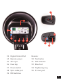
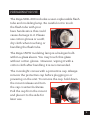
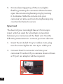
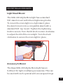
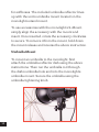
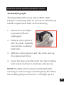
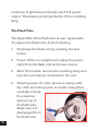
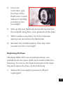
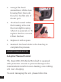
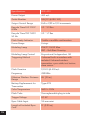
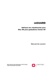
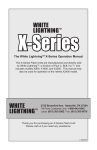
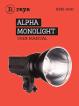
SDR-400
ALPHA
MONOLIGHT
USER MANUAL
INTRODUCTION
Thank you for choosing the Raya SDR-400 Alpha
Monolight.
This
all-in-one,
fan-cooled
400w/s
monolight uses intelligent technology, creating a sleek,
compact, and easy to use flash unit. Constructed with
a high-quality rubberized polymer housing, the SDR400 is operated with a clearly marked digital control
panel, creating a simple and intuitive workflow for
controlling everything from power levels in one-tenth
stop increments to the built-in wireless receiver.
The durable SDR-400 has an integrated four-channel
wireless receiver that communicates with an included
wireless transmitter. You can easily change the
wireless frequency of the monolight with DIP switches.
Additionally, the monolight includes five individual
slave settings, ranging from a regular slave mode to
modes that will trigger the unit with external flashes
with up to three pre-flashes.
The Raya SDR-400 Alpha Monolight is equipped
with advanced protection circuit controls to prevent
several types of common high-voltage electronics
issues, including over-heating, over-volting, and overcharging.
This Raya studio flash is ideal for photography
enthusiasts looking for an economical high-powered
flash unit with the convenience of wireless triggering.
The unit’s auto-seeking multi-voltage (100~240V,
50/60 Hz) circuitry and compact construction make
this monolight ideal for local and international use (an
AC plug adapter will be necessary for use outside the
U.S. as well as a 220-240V modeling lamp).
FEATURES
Multi-voltage 100~240VAC 50/60Hz
Built-in 4-channel radio receiver for wireless
function
Includes 4-channel radio transmitter for wireless
triggering
Lightweight, compact, and easily transported
Durable, high-quality, rubberized polymer
housing
Easy to view LED power display
Intuitive operating
Precision light-output adjustments of 6 f-stops
from full to 1/32 in 0.1 stop increments
Proportional or Independent modeling lamp
control
150W 110V quartz halogen modeling lamp
Quick recycle time
Fast flash duration
Fan-cooled
Adaptive thermal control protects against
overheating and overvoltage damage
4
Auto power dump feature
Built-in optical slave
Sync delay and red eye reduction functions
Model lamp SSC (Soft Start Circuitry)
Plug-in user-replaceable flashtube
7˝ umbrella/grid reflector
BOX CONTENTS
SDR-400 Alpha Monolight
Umbrella reflector with 7˝ grid inset
4-channel wireless transmitter
Protective cap
AC cord - 16´ (4.9 m)
Sync cord - 11´ (3.35 m)
5
OVERVIEW
12
2
1
3
4
11
5
8
7
10
9
6
1.
6
S-Mount (reflector
mount)
7.
Umbrella mount
2. Mount release
8. Umbrella tightening
knob
3. Modeling light
9. Mount tightening knob
4. Modeling light socket
10. Tilt knob
5. Flash tube
11.Fan
6. 5/8˝ stand mount
12.Handle
20
14
13
22
19
15
16
17
18
21
23
24
13. Digital Control Pad
Remote:
14. Remote sensor
20. Test button
15. AC input
21. DIP switches
16. Fuse bay
22. Shoe foot
17. Power switch
23. Tightening ring
18. Sync cable port
24. 3.5 mm port
19. DIP switches
7
PRECAUTIONS ⚠ ⚡
8
•
Please read and follow these instructions and keep this
manual in a safe place.
•
Keep this product away from water and any flammable gases
or liquids.
•
Make sure this product is turned off when plugging it into an
electrical outlet.
•
Use only the correct, recommended voltage.
•
Do not attempt to disassemble or repair this product. There
are components inside that can produce a hazardous electric
shock.
•
Handle this product with care.
•
Do not stare at the lights when they are powered on.
•
Avoid rapid, high-power flashing.
•
Excessive heat shortens the life span of flash tubes, modeling
lamps, and internal components.
•
If not used for two months, turn the unit on for 30 minutes
and fire the flash several times to charge the capacitors.
•
Always remove the protective cap before plugging in or
powering on the unit.
•
Never operate the flash with the protective cap on.
•
Clean this product with only a soft, dry cloth.
•
Always wear cotton gloves when handling the flashtube.
•
Never open or do repairs on the unit. There are no userserviceable parts.
•
Keep this product away from children.
•
Make sure everything is secure before proceeding.
•
Make sure that this product is intact and that there are no
missing parts before use.
•
All photos are for illustrative purposes only.
PREPARING FOR USE
The Raya SDR-400 includes a user-replaceable flash
tube and modeling lamp. Be careful not to touch
the flash tube with your
bare hands since this could
cause damage to it. Please
use cotton gloves or a soft,
dry cloth when touching or
handling the flash tube.
The Raya 150W modeling lamp is a halogen bulb
within a glass sleeve. You may touch this glass
without cotton gloves. However, wiping it with a
cotton cloth after handling it is recommended.
The monolight comes with a protective cap. Always
remove the protective cap before plugging in or
powering on the unit. To remove the cap, hold down
the mount release and turn
the cap counterclockwise.
Pull the cap from the mount
and place it to the side for
later use.
9
GENERAL OPERATION INSTRUCTIONS
To begin using the monolight, do the following:
NOTE: Ensure the power switch is set to OFF before
connecting the monolight’s power cord.
1. Plug the cord into the AC wall outlet, then plug
the connector into the AC input on the flash unit.
2. Power on the monolight by flipping the power
switch located on the back of the unit.
3. Turn on the modeling light using the modeling
light button. For more information about how to
operate the modeling light, refer to the Setting
the Modeling Light Power Output section on
page 24.
4. Connect your camera to the monolight to begin
triggering.
CONNECTING YOUR CAMERA TO THE MONOLIGHT
The Raya SDR-400 Alpha Monolight has two
triggering options out of the box – wireless and
sync cord connections. Please reference the
following instructions to connect your camera to the
monolight.
10
Wireless
The Raya SDR-400 has an integrated four-channel
wireless receiver. Using the included transmitter,
you can wirelessly trigger your flash unit from up to
65-feet away. No line-of-sight is required for your
monolight to communicate with the transmitter. Use
the following instructions to set up and wirelessly
trigger your flash.
1. Locate the DIP switches on the
back of the monolight.
2. Set the channel frequency of
your choosing.
3. On the transmitter, set the DIP
switches to the same channel as
on the monolight.
4. Press the test button on the
transmitter to fire the monolight.
Please reference the following chart for channel
settings:
11
5. For wireless triggering of the monolight’s
flash by pressing the camera’s shutter button,
open the remote’s tightening ring by turning
it clockwise. Slide the remote into your
camera’s hot shoe and turn the tightening ring
counterclockwise to secure.
Sync Cord
The back of your monolight has a 3.5 mm sync
input, which is used for a hardwire connection
between your camera and the flash unit. Use the
following instructions to connect your two devices:
1. Insert the included 11’ sync cable’s mini-plug
into the monolight’s 3.5 mm sync cable port.
2. Connect the PC connector end into your
camera’s PC socket. If you camera does not have
a PC port, an adapter will be required.
12
MOUNTING ACCESSORIES
Light Stand Mount
The SDR-400 Alpha Monolight has a standard
5/8” stand mount with tilt and tightening knobs.
To mount the monolight on a light stand, place
the stand mount onto a compatible stand with a
standard 5/8” top mount. Tighten the tightening
knob to secure. Turn the tilt knob counter clockwise
to adjust the tilt of the monolight. Turn the knob
clockwise to secure the monolight in place.
Accessory S-Mount
The Raya SDR-400 Alpha Monolight has an
S-Mount for light-modifying accessories. This can
be used with such optional add-ons as speed rings
13
for softboxes. The included umbrella reflector lines
up with the unit’s umbrella mount located on the
monolight’s stand mount.
To use accessories with the monolight’s S-Mount,
simply align the accessory with the mount and
insert. Once inserted, rotate the accessory clockwise
to secure. To remove it from the mount, hold down
the mount release and reverse the above instruction.
Umbrella Mount
To mount an umbrella to the monolight, first
attach the umbrella reflector dish using the above
instructions. Then run the umbrella rod through
the dish’s umbrella hole and into the monolight’s
umbrella mount. Secure the umbrella using the
umbrella tightening knob.
14
FLASH SETTINGS
Setting the Monolight’s Power Output
The Raya SDR400 Alpha Monolight’s flashtube
has a 6-stop power range, represented by a 10-60
numbered scale on the LED screen. To increase the
power output of the monolight, press the button
on the back of the flash unit. To decrease the power
output, press the button.
NOTE: Each button press changes the power output
by one-tenth of a unit. To increase or decrease whole
numbers displayed on the screen at a faster pace,
hold down the adjustment button.
Setting the Modeling Light Power Output
The Raya SDR400 Alpha Monolight has a 150 watt
user-replaceable modeling light. The modeling
light’s power output is represented by a 10-60
numbered scale on the LED screen. To increase the
modeling light’s power output, press the button.
To decrease the output, press the button.
15
The modeling light has two indicator lights:
Proportional: When the model light is turned
on, the default setting is proportional, as
indicated by the bottom green light. As
you adjust the monolight’s power output
(using the or buttons), the modeling light will
adjust up or down proportionally. This gives you the
general idea where highlights and shadows will fall
in relation to the flash power.
Independent: To change from the default
setting, press the up or down arrow once.
The top green light will glow green, and the
bottom green light will disappear. Blinking
numbers will appear on the LED screen, displaying
the current modeling light output setting. The
numbers will continue to blink while adjusting the
setting. Once the desired number is selected, the
numbers will blink four times, then return to the solid
monolight power output numbers.
NOTE: Each button press changes the power output
by one tenth unit. To increase or decrease the
numbers displayed on the screen faster, hold down
the adjustment button.
16
Auto Power Dump
When lowering the power level, the monolight will
automatically discharge a flash when the new setting
is confirmed. Do not look into the flash tube area
when performing this change.
SLAVE AND PRE-FLASH SETTINGS
The Raya SDR400 Alpha Monolight has five slave
settings. You can toggle between the modes by
repeatedly pushing the slave button until the
required number is indicated by the light on the right
side of the panel.
Default Setting: No LED light is activated. Slave
mode is OFF.
Setting 1: Slave mode ON. A single flash from
another source will trigger the monolight.
Setting 2: The monolight will trigger after a half
second delay. After the first flash from another
source, the monolight will go into a standby mode,
and the SDR-400 will trigger at the next flash.
Setting 3: Monolight will trigger after one preflash.
Setting 4: Monolight will trigger after two preflashes.
Setting 5: Monolight will trigger after three
preflashes.
17
BUTTON GUIDE
1. Test button
a. Manually triggers the monolight at the
current settings.
2. Sound control
a. Turns the confirmation sounds on and off.
3. Slave button
a. Activates slave mode.
4. Slave mode indicator lights
a. Indicates which slave mode is activated.
5. Power output buttons
a. Increases or decreases the power output of
the monolight.
6. Modeling light button
a. Turns the modeling light on or off.
7. Modeling light indicator light when button is
pushed
a. Bottom green light on modeling light button
turns on – default position.
18
b. Indicates that modeling light intensity level
is proportional to the flash tube.
8. Modeling light independent indicator light when
‘up’ or ‘down’ arrow button is pushed
a. Top light on model light button goes on
b. Indicates that the modeling light’s intensity
level is independent of the flash tube’s
output
9. Modeling light intensity level ‘up’ and ‘down’
arrow adjustment buttons
a. Adjusts the intensity level of the modeling
light
b. Turns on independent model light mode and
overrides proportional mode, as displayed in
blinking numbers.
1
2
3
4
5
6
7
8
9
19
DIGITAL CONTROL PANEL GUIDE
LED Screen Guide
Steady Numbers
Steady numbers indicate the monolight’s flashtube
power output, as controlled by the power level
buttons
.
Blinking Numbers
Blinking numbers on the LED screen indicate
the intensity levels of the modeling light during
adjustment, as controlled by the modeling light
output buttons
. The numbers only blink when
the modeling light intensity level is being adjusted. It
will stop blinking after four blinks.
Confirmation
When the monolight’s sound is turned off and the
modeling light is turned on, the modeling light will
turn off after a flashtube triggering and come back
on once the unit has recycled, providing a visual
confirmation that the unit is ready to flash again at
100%.
20
INSTALLATION & REPLACEMENT GUIDE
The Modeling Light
The Raya SDR-400 comes with a 150W, 110V
halogen model lamp bulb. To remove an old bulb and
install a replacement bulb, do the following:
1. Ensure the monolight
is powered off and
unplugged.
2. Using a cotton glove or
soft, dry cloth, carefully
unscrew the modeling
light bulb.
3. With the cotton glove or soft, dry cloth, pick up
the replacement tube.
4. Insert the back end of the bulb into the modeling
bulb socket and turn it clockwise until secure.
NOTE: The SDR-400 has built-in SSC (Soft Start
Circuitry) to ensure longer modeling lamp life. When
the modeling lamp is turned on, it will light up at a
21
minimum brightness and slowly reach full power
output. This feature prolongs the life of the modeling
lamp.
The Flash Tube
The Raya SDR-400’s flash tube is user-replaceable.
To replace the flash tube, do the following:
1. Discharge the flash unit by pressing the test
button.
2. Power off the monolight and unplug the power
cable from the flash unit and power source.
3. After 15 minutes, remove the modeling lamp and
any other accessory connected to the unit.
4. Wearing a pair of cotton gloves or using a soft,
dry cloth and using a pair of needle-nose pliers,
carefully unhook
the retention
spring loop of
the flash tube.
Make sure it is
disengaged from
the flash tube.
22
5. Once it is
unhooked, grip
the base of the
flash tube on each
side and carefully
pull it from the
monolight.
6. Pick up the new flashtube and push its pins into
the sockets using firm, even pressure at the base.
7. With needle-nose pliers, hook the retention
spring over and above the flash tube.
8. Reinsert the modeling lamp, then any other
accessory to the monolight.
Replacing the Fuse
The Raya SDR-400 comes with two fuses: one
installed and one spare. Both are located within the
fuse bay. To remove the fuse housing from the fuse
bay and replace the fuse, do the following:
1. Ensure the monolight is powered off and
unplugged.
23
2. Using a flat head
screwdriver, lift the fuse
housing from the nook
found on the flat side of
the AC jack.
3. The fuse located within
the housing is the one
the monolight is using
when it is powered on. To
replace the fuse, remove
it from the box.
4. Replace it with a spare.
5. Reattach the fuse holder to the fuse bay to
complete the process.
MAINTENANCE NOTES
Adaptive Thermal Control
The Raya SDR-400 Alpha Monolight is equipped
with protection circuits to prevent damage to the
internal electronics from over-heating, over-volting,
and over-charging.
To avoid damaging the unit, please follow the
24
information outlined in the Precautions section.
NOTE: The fan turns on when the unit’s internal heat
reaches 122°F (50°C).
Error Codes
The Raya SDR-400’s LED screen will indicate one of
the following codes when it detects an issue.
E1 = One or more of the capacitors is overvolting. If
this error occurs, turn the unit off and let it rest for a
few minutes. If the error message comes up again,
contact the manufacturer.
E2 = The monolight is overheating (176°F, 80°C). The
error will disappear once the unit has cooled. Press
any button (except the power button) to remove the
error message. The fan will continue to cool the unit
until the heat has dissipated after 5-10 minutes. If
the monolight is turned off, the light will take longer
to cool.
E3 = The monolight’s input voltage is more than 265
volts. If this error occurs, turn the unit off and let it
rest for a few minutes. If the error message comes up
again, contact the manufacturer.
25
26
Specifications
SDR-400
Power Output
400 w/s
Guide Number
165 (10´ @ ISO 100)
Output Control Range
Full to 1/32 in 1/10 increments
Recycle Time 100~120V
60Hz
0.2 ~ 2.2 Sec
Recycle Time 220~240V
50 Hz
0.2 ~ 1.7 Sec
Flash Ready Indicator
Visible or audible confirmation
Power Range
6 stops
Modeling Lamp
E26/27, 150W Max
SSC – Soft Start Circuitry
Modeling Lamp Control
Proportional, Independent, Off
Triggering Method
4 channel built-in wireless with
included 4 channel wireless
transmitter, sync cable, test button,
slave sensor
Flash Duration
1/1000 @ 400w/s
Frequency
433 MHz
Effective Wireless Distance
Range
65´ (20 m)
Battery Replacement for
Transmitter
Type A23
Color Temperature
5600 ± 100k
Flash Tube
User replaceable plug-in tube
Trigger Voltage
DC 5V
Sync Cable Input
3.5 mm mini
Length of Included Sync
Cord
11´ (3.35 m)
Specifications
SDR-400
Slave Settings
Sync delay, red-eye reduction,
synchronous
Cooling Fan
ATC (auto temperature control)
Touch Pad Controls
Yes
Auto Power Dump
Yes
Adaptive Thermal Control
Yes
Housing Material
Durable rubberized high strength
polymer shell
Accessory Mount
Compatibility
S-Type Mount
Power Source
100~240VAC 50/60 Hz
Circuit Protection
5G10A fuse
Length of Included AC Cord
16´ (4.9 m)
Weight
3.95 lbs (1.8 kg)
Dimensions (with flash tube
cover and stand mount)
13˝ × 5˝ × 8˝ (33 × 12.7 × 20.3 cm)
FCC DISCLAIMER:
This device complies with Part 15 of the FCC Rules. Operation
is subject to the following two conditions: (1) this device may
not cause harmful interference, and (2) this device must accept
any interference received, including interference that may cause
undesired operation.
Made in China
27
ONE-YEAR LIMITED WARRANTY
This RAYA product is warranted to the original purchaser to be
free from defects in materials and workmanship under normal
consumer use for a period of one (1) year from the original
purchase date or thirty (30) days after replacement, whichever
occurs later. The warranty provider’s responsibility with respect
to this limited warranty shall be limited solely to repair or
replacement, at the provider’s discretion, of any product that fails
during normal use of this product in its intended manner and in
its intended environment. Inoperability of the product or part(s)
shall be determined by the warranty provider. If the product has
been discontinued, the warranty provider reserves the right to
replace it with a model of equivalent quality and function.
This warranty does not cover damage or defect caused by misuse,
neglect, accident, alteration, abuse, improper installation or
maintenance. EXCEPT AS PROVIDED HEREIN, THE WARRANTY
PROVIDER MAKES NEITHER ANY EXPRESS WARRANTIES NOR
ANY IMPLIED WARRANTIES, INCLUDING BUT NOT LIMITED
TO ANY IMPLIED WARRANTY OF MERCHANTABILITY OR
FITNESS FOR A PARTICULAR PURPOSE. This warranty provides
you with specific legal rights, and you may also have additional
rights that vary from state to state.
To obtain warranty coverage, contact the Raya Customer Service
Department to obtain a return merchandise authorization
(“RMA”) number, and return the defective product to Raya along
with the RMA number and proof of purchase. Shipment of the
defective product is at the purchaser’s own risk and expense.
For more information or to arrange service, visit
rayalighting.com or call Customer Service at 212-594-2353.
Product warranty provided by the Gradus Group.
www.gradusgroup.com
RAYA is a registered trademark of the Gradus Group.
© 2014 Gradus Group LLC. All Rights Reserved.
GG4