1
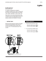
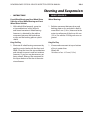
Mechanic’s Guide
New Brunswick Official Vehicle
Inspection Station Manual
www.gnb.ca/publicsafety
New Brunswick Official Vehicle Inspection Station Manual:
Mechanic’s Guide
Published under the authority of the
Province of New Brunswick,
Department of Public Safety
P.O. Box 6000
Fredericton, NB E3B 5H1
ISBN 1-55396-054-8
Revised August 2015
10155 NEW BRUNSWICK OFFICIAL VEHICLE INSPECTION STATION MANUAL
Table of Contents
SECTION 1 ……………………………………………………………………………………………… 5
Introduction ………………………………………………………………………………………… 5
Station Licence Application ……………………………………………………………………… 7
Requirements for Licensing of an Official Vehicle Inspection Station …………………………… 8
Types of Inspection Licences Issued ……………………………………………………………… 9
Equipment ……………………………………………………………………………………… 10
Official Vehicle Inspection Station Sign ………………………………………………………… 10
Fee Chart ………………………………………………………………………………………… 10
Duties and Responsibilities of an Inspection Station Licensee ………………………………… 11
Role of the Department of Public Safety Motor Vehicle Inspector …………………………… 12
Vehicle Inspection Staff Qualifications ………………………………………………………… 13
Mechanic Certificates …………………………………………………………………………… 14
Certified Mechanic Responsibilities …………………………………………………………… 15
Vehicle Registration ……………………………………………………………………………… 15
Approval Sticker Location ……………………………………………………………………… 16
Rejection Sticker Location ……………………………………………………………………… 16
Approval Sticker and Report Form Ordering …………………………………………………… 16
Sale of Vehicle for Junk, Parts or Salvage ……………………………………………………… 17
Approval Stickers and Report Books …………………………………………………………… 17
Rejection Stickers ……………………………………………………………………………… 17
Re-Inspection …………………………………………………………………………………… 18
Replacement Stickers …………………………………………………………………………… 18
Inspection Routine ……………………………………………………………………………… 19
Vehicle Inspection Report ……………………………………………………………………… 19
SECTION 2 …………………………………………………………………………………………… 20
SECTION 3 …………………………………………………………………………………………… 52
NEW BRUNSWICK OFFICIAL VEHICLE INSPECTION STATION MANUAL
SECTION 1
Introduction
Upon applying to offer the services of a New Brunswick Official Vehicle Inspection Station, the
licensee accepts the responsibility to properly inspect all vehicles submitted for inspection. Any
licensee who fails to fully maintain the standards outlined in the Official Vehicle Inspection
Station Manual is subject to the loss of the privilege of conducting official motor vehicle
inspections.
The procedures as outlined herein should be carefully reviewed by your certified mechanics, as
well as any other staff members involved in the motor vehicle inspection program. There can
be no meaningful highway safety without safe vehicles. Members of the motoring public count
on the careful work of licenced mechanics, who conduct the annual inspections, to reduce the
likelihood of accident or injury, due to mechanical failure of their motor vehicle.
The information in this Manual is based upon the New Brunswick Motor Vehicle Act and upon
Regulations to the Motor Vehicle Act. The Motor Vehicle Act may be viewed on the Internet at
http://www.gnb.ca/acts/acts/m-17.htm
A list of all Regulations under the Motor Vehicle Act may also be viewed on the Internet at http://
www.gnb.ca/0062/regs/m-17reg.htm
In particular the Regulation setting out the standards for Official New Brunswick Motor Vehicle
Inspection Stations may be found at http://www.gnb.ca/0062/regs/83-185.htm
The information found in this manual is based on the direction found in the Motor Vehicle Act and
in the Regulations to the Act. Information in this manual will be used when inspecting:
•
•
•
•
•
•
•
•
Passenger vehicles;
Station wagons;
Family motor coaches;
Antique automobiles;
Taxis;
Commercial vehicles (with unladen curb mass of 3499 kilograms or less);
Recreational trailers; and
Utility trailers (but does not apply to vehicles with air brakes)
5
NEW BRUNSWICK OFFICIAL VEHICLE INSPECTION STATION MANUAL
Careful use of the information in this manual will ensure that all inspections are performed in the
manner prescribed by law. Included are:
•
•
•
•
Procedures;
Requirements;
Performance Standards, for inspection of those items identified for examination under the
Compulsory Vehicle Inspection Program, in New Brunswick; as well as
Reasons for which various items might be considered unsafe.
Please note
•
•
•
•
•
•
6
All items listed must be inspected.
Each procedure outlined for the inspection must be completed as directed.
Careful attention must be paid to the reasons for rejection.
An approval sticker must not be issued for a vehicle which fails to meet the minimum safety
requirements, as identified by this program.
Every person who makes a false statement in completing a Vehicle Inspection Report may be
found guilty of an offence and be subject to penalties prescribed by the Motor Vehicle Act.
Also, a Motor Vehicle Repair Certificate of Qualification as issued under Occupation
Regulation – Apprenticeship and Occupational Certification Act may be subject to suspension or
cancellation.
NEW BRUNSWICK OFFICIAL VEHICLE INSPECTION STATION MANUAL
Station Licence Application
An application to be licenced as a New Brunswick Official Vehicle Inspection Station may be
obtained from the:
Motor Vehicle Branch
Department of Public Safety
P.O. Box 6000
Fredericton, NB E3B 5H1
Telephone: 506-453-2410
Fax: 506-453-7455
Applications are also available at any Service New Brunswick office in the province.
Each application submitted to the Licensing Officer of the Motor Vehicle Branch of Public Safety
must be accompanied by payment of the required licence fee. In the event of rejection of an
application, the fee will not be returned. A statement of responsibilities is enclosed with the
application forms.
Prior to approval for a licence, each applicant’s premises will be visited by a Motor Vehicle
Inspector to determine suitability for appointment as a New Brunswick Official Vehicle Inspection
Station. A report of the Inspector’s findings will be provided to a Licensing Officer of the Licensing
Bureau. The Licensing Officer will then evaluate the completed application information and the
Inspector’s report. If found to be acceptable, the Applicant will be advised of approval as a New
Brunswick Official Motor Vehicle Inspection Station Licensee, by the Licensing Officer.
All cheques or money orders must be made payable to the Minister of Finance.
7
NEW BRUNSWICK OFFICIAL VEHICLE INSPECTION STATION MANUAL
Requirements for Licensing of an
Official Vehicle Inspection Station
According to the classification of inspection licence issued, each station must employ at least one
licensed mechanic, who possesses a Certificate of Qualification in one of the following trades:
•
•
•
Motor Vehicle Repair (Mechanical);
Motor Vehicle Repair (Steering, Suspension and Brakes);
Motor Vehicle Repair (Truck & Transport) or Truck Trailer repairer as issued under Occupation
Regulation – Apprenticeship and Occupational Certification Act.
Each station must have sufficient inside working space to accommodate:
•
•
•
the vehicle during its inspection;
the certified mechanic; and all
tools and equipment necessary to perform the inspection.
Minimum inside space requirements:
a) not less than 3.5 metres (11.6’) in width
b) 7.5 metres (25’) in length (if mechanical headlamp aimers or headlamp testing equipment is
used)
c) 15 metres (50’) in length (if headlamp aim testing screen is used)
d) 5 metres (16.6’) additional length is required for heavy vehicle inspection stations.
8
NEW BRUNSWICK OFFICIAL VEHICLE INSPECTION STATION MANUAL
Types of Inspection Licences Issued
1. Regular Inspection
Issued to stations conducting inspections on:
• All buses (except school buses or contracted conveyances)
• Motor vehicles with an unladen curb mass of 3499 kilograms or less;
• Utility trailers; and
• Recreational trailers (excluding any vehicle with air brakes)
2. School Bus Inspection
Issued to stations conducting inspections on:
• School buses; and
• Contracted conveyances.
3. Heavy Vehicle Inspection
Issued to stations conducting inspections on:
• Buses (except school buses or contracted conveyances);
• Motor vehicles 3500 kilograms unladened curb mass or more.;
• Semi-trailers;
• Trailers; and
• Pole trailers.
4. Fleet Inspection
Issued to stations inspecting:
• A fleet of ten or more vehicles - Restricted to vehicles registered or operated by the
licensee. (except school buses or contracted conveyances).
Licence privileges may be combined. For example a licence may be issued to allow for regular
inspections and also for heavy inspections.
Note
Special Recreational Trailer Inspection privileges may be extended to retail recreational trailer
outlets. Please inquire to the Licensing Manager at the Motor Vehicle Branch of Department of
Public Safety, Fredericton, NB.
9
NEW BRUNSWICK OFFICIAL VEHICLE INSPECTION STATION MANUAL
Equipment
The following list of equipment is not intended as a complete list but rather as a guide describing
tools and parts which should be available to an inspection mechanic:
•
•
•
•
•
•
•
•
•
•
•
•
Common hand tools;
Headlamp aiming device (one of 3 types);
Hoisting device (suitable for the vehicles being inspected);
Trouble light;
Tire pressure gauge;
Tire tread depth gauge;
Brake drum and brake rotor gauge;
Sealed beam replacement units;
Brake fluid;
Assorted lamps;
Fuses; and
Windshield wiper blades.
Official Vehicle Inspection Station Sign
The sign provided, designating the facility as an Official Inspection Station must be:
•
•
Displayed unaltered in a prominent place to inform the motoring public of the Licensee’s
official authority;
Maintained in good condition by the Licensee.
Fee Chart
The fee chart:
•
•
10
Designates fees applicable to all vehicles which are required to be inspected by the
compulsory vehicle inspection program in New Brunswick;
Must be posted where it can be viewed by the public at all times.
NEW BRUNSWICK OFFICIAL VEHICLE INSPECTION STATION MANUAL
Duties and Responsibilities of an
Inspection Station Licensee
Each Official Vehicle Inspection Station licensee must fulfil the following responsibilities:
1. Each vehicle inspection must be made by, or under the direct supervision of, a mechanic who
possesses the required Certificate of Qualification as issued under Occupational Regulation
– Apprenticeship and Occupational Certification Act.
2. The provision of inspection services to the public must conform with all the standards
outlined in this Manual.
3. Inspection approval limits established must be applied to each vehicle inspected.
4. The tools and equipment available at the Inspection Station must be adequate for inspection
and repair of the vehicle being inspected. The headlamp aim inspection equipment must
meet the approval of the Department of Public Safety Motor Vehicle Inspector.
5. Careful completion of inspection reports, proper distribution of report copies and control over
stickers must be assured at all times.
6. The lending or borrowing of inspection supplies between Inspection Stations is strictly
prohibited.
7. Fees charged the public for vehicle inspections shall be only at the rate prescribed by the
Motor Vehicle Act Regulations.
8. The Inspection Station Licensee must notify the Manager of Licensing at the Licensing &
Registration Branch immediately of:
a)Complaints
b)Loss or theft of stickers or report forms
c)Request to adopt procedural changes
d)Report errors in vehicle registration to the Manager, Licensing and Registration Branch,
Department of Public Safety
e)Desire to cease operations as an Inspection Station and have all inspection supplies
returned
• Stickers
• Report books
• Manuals
9. Credit for inspection stickers will be considered only when an inspection station has
permanently ceased operation.
10.The following items must be displayed in full public view at all times:
• Official Motor Vehicle Inspection Station Licences;
• Procedure charts; and
• Official Motor Vehicle Inspection Station Signs.
11.All inspection materials must be available for inspection by a Peace Officer, Motor Vehicle
Inspector or any Official of the Motor Vehicle Branch.
11
NEW BRUNSWICK OFFICIAL VEHICLE INSPECTION STATION MANUAL
12.Renewal of the Official Vehicle Inspection Station Licence must be made prior to December
31st of each year, together with full payment of the licence fee.
13.The Inspection Station Licence is valid for the issued location only. If a Licensee wishes to
perform vehicle inspections at more than one location, a separate licence is required for each
location.
14.The Inspection Station Licensee is responsible for all inspection duties under their licence,
including inspection work performed by any of their employees.
15.The Inspection Station Licensee is responsible for maintaining an adequate stock of
inspection supplies, to provide continuous service to the public.
Role of the Department of Public Safety
Motor Vehicle Inspector
Motor Vehicle Inspectors, employed by the Department of Public Safety, are both peace officers
and journeyman mechanics. The Inspectors will make direct contact with the Inspection Station
licensee, normally on-site at the inspection station.
Initially, Motor Vehicle Inspectors will conduct an on-site visit to inspect the premises of each
Inspection Station. This inspection is done to ensure that all requirements are met with regard to
space, equipment and staff. Inspectors will then normally visit every Inspection Station on one or
more occasions each year.
The Inspectors are also prepared to review and investigate complaints lodged by both Inspection
Stations and by members of the public. They are available to provide assistance to both groups at
any time with regard to:
• Regulations;
• Procedures; and
• General inquiries.
Moncton
Fredericton
Saint John
Bathurst
Edmundston
RegionRegionRegionRegionRegion
12
856-2958444-4814658-3005547-2940735-2030
NEW BRUNSWICK OFFICIAL VEHICLE INSPECTION STATION MANUAL
Inquiries regarding:
•
•
•
•
Vehicle Inspection;
Garage And Dealer Licences;
Inspection Stickers; and
Vehicle Inspectors should be directed to the Manager,
Motor Vehicle Branch
Department Of Public Safety
P. O. Box 6000
Fredericton, NB E3B 5H1
Telephone: 506-453-2410
Fax 506-453-7455
Vehicle Inspection Staff Qualifications
The motor vehicle mechanics who operate under this program are required to be holders of
certificates of qualification in the:
•
•
•
•
Motor Vehicle Mechanic (Automobile);
Motor Vehicle Mechanic (Truck and Transport);
Motor Vehicle Mechanic (Steering Suspension and Brakes); or
Truck and Trailer Mechanic occupation as issued under Occupation Regulation –
Apprenticeship and Occupational Certification Act.
Each Official Vehicle Inspection Station is required to have at least one appropriately licensed
mechanic on duty while a vehicle is being inspected under the Compulsory Vehicle Inspection
Program.
13
NEW BRUNSWICK OFFICIAL VEHICLE INSPECTION STATION MANUAL
Mechanic Certificates
The following outlines the required mechanic’s Certificates of Qualification for the various types
of vehicles inspected.
1. All motor vehicles and buses 3499 kilograms or less unladened curb mass, recreational trailers
and utility trailers may be inspected by certified mechanics who are holders of any of the
following certificates of qualifications:
a)Motor Vehicle Mechanic/Automotive Service Technician (Automobile)
b)Motor Vehicle Mechanic/Automotive Service Technician (Steering Suspension & Brakes)
c)Motor Vehicle Mechanic/Truck & Transport Service Technician (Truck & Transport)
The above mechanics can inspect any trailer no matter its size except those trailers which
have an air brake system. Any trailer with air brakes can only be inspected by mechanics
who hold licences in the following categories:
a)Truck and Transport Service Technician (Truck & Transport)
b)Commercial Trailer Technician (Truck Trailer Repairer)
2. All motor vehicles, buses, and semi-trailers, trailers or pole trailers may be inspected by
certified mechanics who hold a Certificate of Qualification in Motor Vehicle Mechanic (Truck &
Transport).
3. All semi-trailers, trailers, pole trailers, recreational trailers and utility trailers requiring
inspection may be inspected by certified mechanics who are holders of the Certificate of
Qualification, Truck Trailer Repairer Trade.
4. Special inspection provisions may apply to retail recreational trailer dealers, who are primarily
engaged in the sale and repair of recreational trailers. Please contact a Licensing Officer at the
Motor Vehicle Branch of Department of Public Safety, Fredericton (506-453-2410).
5. All motorized vehicles with air brakes must be inspected by a Truck and Transport Mechanic.
Note
A Motor Vehicle Mechanic (Truck and Transport) can perform safety inspections on any vehicle,
with no weight restrictions.
14
NEW BRUNSWICK OFFICIAL VEHICLE INSPECTION STATION MANUAL
Certified Mechanic Responsibilities
The inspection station mechanic must:
1. Become thoroughly familiar with the vehicle inspection requirements as outlined in the
Official Motor Vehicle Inspection Manual and be able to satisfy the Motor Vehicle Inspector
with the level of knowledge held.
2. Directly supervise or perform each vehicle inspection according to the outlined procedure
and, therefore, assure vehicle owners that their inspection was properly carried out.
3. Exercise care in completing the Vehicle Inspection Report form legibly (in ink), and in
recording the correct sticker number placed on the vehicle by the licensed mechanic.
4. Remove the inspection sticker on a vehicle prior to beginning the inspection.
5. Never pre-sign Vehicle Inspection Reports.
Vehicle Registration
During the inspection of vehicle components, the certified mechanic is required to obtain the
vehicle registration from the vehicle owner. The registration plate and serial number shown
should match the plate and serial number attached to the vehicle.
Where the plate and serial number are not identical, the certified mechanic must:
a) Examine the vehicle plate and serial number and compare this with the plate and serial
number shown on the vehicle registration;
b) Record the correct vehicle plate and serial number on the Vehicle Inspection Report Form.
Contact the Motor Vehicle Inspector in your area to advise of the discrepancy.
Moncton
Fredericton
Saint John
Bathurst
Edmundston
RegionRegionRegionRegionRegion
856-2958444-4814658-3005547-2940735-2030
Note
The fact that the plate(s) or serial number on the vehicle does not match the plate(s) or serial
number on the registration is not sufficient reason to cause the vehicle to be rejected. By notifying
the Motor Vehicle Branch, Department of Public Safety, of the error the necessary corrections can
be made. (506-453-2410)
15
NEW BRUNSWICK OFFICIAL VEHICLE INSPECTION STATION MANUAL
Vehicles requiring inspection, where no registration certificate is available, may be inspected in
the normal manner remembering to indicate on the Vehicle Inspection Report Form that the
registration has not been verified.
Note
Former school buses converted to other uses, i.e. church buses, family motor coach, shall be
refused inspection if the following conditions have not been completed:
1. Colour must be changed from that displayed by provincial school buses.
2. Amber and red flashing warning lights must be removed.
Approval Sticker Location
All stickers prefixed HV, AV or SV (with adhesive on the face side) shall be placed on the inside
lower left corner of the windshield on all motor vehicles required to be inspected.
All stickers prefixed AT (with adhesive on the back) shall be placed on the left side, front corner, at
a readable height on all trailers, pole trailers or semi-trailers required to be inspected.
Rejection Sticker Location
a) On the outside lower left corner of the windshield on all motor vehicles failing to pass
inspection.
b) On the left side front corner, covering any existing sticker, at a readable height, on all semitrailers, pole trailers or trailers failing to pass inspection.
Approval Sticker and Report Form Ordering
It is the responsibility of each Inspection Station Licensee to maintain an adequate stock of
inspection supplies to provide continuous inspection services to the public.
The control and safeguarding of inspection supplies is the responsibility of the Inspection Station
Licensee. Only an Inspection Station Licensee or their designated agent may complete and order
these supplies, since safeguarding and accounting is the Licensee’s responsibility. Upon receipt of
supplies the Licensee is required to verify quantities and acknowledge receipt of the shipment on
the form provided.
The ordering of inspection stickers should be carefully monitored during the last months of the
year to prevent over-stocking. Please return only complete books of ten (10) stickers. The amount
will be credited towards your next sticker purchase.
16
NEW BRUNSWICK OFFICIAL VEHICLE INSPECTION STATION MANUAL
Sale of Vehicle for Junk, Parts or Salvage
When a vehicle is to be disposed of for any of these noted reasons, any current year Approval
Certificate must be removed and destroyed.
Approval Stickers and Report Books
•
•
•
•
•
The Approval Sticker must be punched to designate the month and year in which the
Approval Sticker will expire.
When punching Approval Stickers, use caution to ensure correct validation.
Incorrectly punched stickers must be replaced at the expense of the Licensee.
Approval Stickers and Report Books must be used in the order of the numbers indicated on
them.
Strict control over sticker issue must be maintained, by the Licensee, at all times.
Rejection Stickers
•
•
•
•
•
Rejection sticker information must be completed by the certified mechanic, on the front side
of the sticker, showing the date of inspection.
A rejection sticker will be issued when a vehicle fails to meet the minimum safety
requirements outlined by this manual.
Operation of an unsafe vehicle is an offence, under the Motor Vehicle Act, Section 206(1):
No person shall operate and no owner shall cause or knowingly permit to be operated any vehicle
or combination of vehicles that
(a) is in such unsafe condition as to endanger any person…
Two consecutive rejection stickers cannot be issued for a vehicle, (in any one year) unless
approved by the Registrar of Motor Vehicles.
Rejection stickers are to be removed by a certified mechanic and replaced with an approved
sticker, after all of the previously failed items have been repaired, re-inspected and approved.
17
NEW BRUNSWICK OFFICIAL VEHICLE INSPECTION STATION MANUAL
Re-Inspection
The space denoted on the Vehicle Inspection Report Forms as Previous Inspection Report No.
must be used in four instances:
1. When re-inspection of a vehicle is necessary due to failure on first attempt. Only those
items which have previously failed and have been repaired should be checked if the same
Inspection Station is involved. In such a case, the previous Inspection Report number is noted,
the re-inspection performed and no inspection fee is warranted during the 14-day extension
period.
2. When a vehicle is presented for re-inspection at other than the original inspection station,
it shall be re-inspected and charged the full inspection fee.
3. When a vehicle is presented for re-inspection, at the same inspection station, following the
elapse of the 14-day extension period, it shall be totally re-inspected and charged the full
inspection fee.
4. When replacement of an approval sticker is issued due to windshield replacement (see below
for details on this matter).
Note
In no instance of re-inspection must a rejected vehicle sticker be removed until after the reinspection items have been approved. Rejection stickers can only be issued once to any one
vehicle, allowing only one 14-day period in any one year, unless an extension is approved by the
Registrar of Motor Vehicles.
Replacement Stickers
When replacement of an Approval Sticker is necessary (e.g. windshield replacement) this can
be achieved at the original Inspection Station, or at any station which is licensed to inspect this
category of vehicle, by the certified mechanic completing the following:
1.
2.
3.
4.
5.
18
Record the previous report number on the new report form.
Check off the box marked replacement.
Issue and record on the new report form, replacement sticker number.
Punch out the replacement sticker with an expiry date identical to that of the original sticker.
The fee for Approval Sticker replacement is as prescribed in Section 7(4) of
Regulation 83-185.
NEW BRUNSWICK OFFICIAL VEHICLE INSPECTION STATION MANUAL
Inspection Routine
1. All inspections must be performed on the premises which the Motor Vehicle Branch has
licensed as an Official Inspection Station.
2. The first step is always to remove any existing sticker, except in the case of AT (annual trailer
sticker) which may be attached to an easily marred surface of a trailer. In this case a new
sticker must be placed over the sticker being replaced.
3. There is no precise required sequence for completing vehicle inspections excepting item 2
here above. Each certified mechanic is free to develop a procedure which fulfils all legislative
requirements and appears to be the most suitable for that station or vehicle.
Vehicle Inspection Report
After a vehicle has been fully inspected an inspection report form must be completed reflecting
the nature of the findings for that particular vehicle.
1. Each report must be printed so it can be easily read;
2. All required report items must be completed;
3. The first report part (yellow copy) must be issued to the vehicle owner;
4. The second report part (white copy) must be forwarded to the Manager of Licensing at the
Licensing & Registration Branch, either on a monthly basis, or with each order of inspection
supplies, whichever occurs first;
5. The third report part (pink copy) must be retained at the inspection station for a period of not
less than two years, from date of issue; and
6. In the case of school bus or contracted conveyance, report parts 1, 2, and 3 are sent to the
locations indicated on the forms, while the fourth part is retained at the Inspection Station, for
a period of not less than one year from date of issue.
19
NEW BRUNSWICK OFFICIAL VEHICLE INSPECTION STATION MANUAL
SECTION 2
Requirements and
Performance Standards
2.1.1
NEW BRUNSWICK OFFICIAL VEHICLE INSPECTION STATION MANUAL
Glass
• INSTRUCTIONS
Critical Vision Area
For the purpose of this Vehicle Inspection
Program, the critical vision area of windshield
is defined to include all of that area swept
by the windshield wiper blades properly
adjusted and using factory installed wiper
arms and blades or equivalent replacements.
REJECT VEHICLE IF:
1. Any treatment coating or application of
coloured spray or material or any opaque
or reflective material has been applied to
the windshield, side wings, side windows
to right or left of the driver.
2. The windshield contains any cracks,
fractures or other defects in the critical
vision area.
3. The windshield, side wings, side or rear
windows are broken in any area exposing
sharp or jagged edges.
4. The windshield is discoloured in the
critical vision area.
NOTE
Windshields having small stone nicks or chips not over 13 mm (1/2 in.) long are not to be
considered grounds for rejection. All other glass requirements apply. All replacement glass in any
vehicle or motor vehicle shall be of the safety type.
REVISED FEBRUARY 2010
2.2.1
NEW BRUNSWICK OFFICIAL VEHICLE INSPECTION STATION MANUAL
Horn(s)
• INSTRUCTIONS
Every motor vehicle when operated upon
a highway shall be equipped with a horn
audible at a distance of not less than 60
metres (200 ft.).
REJECT VEHICLE IF:
1. The horn is not securely fastened to the
vehicle.
2. The horn button or actuating device does
not function properly.
3. The output of a horn is insufficient to
produce an adequate warning under
normal conditions at a distance of 60
metres (200 ft.).
4. Push buttons not to replace original
steering wheel horn button.
NOTE
If a vehicle is factory equipped with more than one horn, all must operate properly.
REVISED JANUARY 2004
2.3.1
NEW BRUNSWICK OFFICIAL VEHICLE INSPECTION STATION MANUAL
Windshield Wiper(s)
• INSTRUCTIONS
Every motor vehicle shall be equipped with a
windshield cleaning device.
REJECT VEHICLE IF:
1. The vehicle is not equipped with factory
installed windshield wiper blades, wiper
arms or equivalent replacements.
2. The windshield wiper blades show signs of
physical breakdown of the rubber wiping
element.
3. The arms fail to return to original position
or the blade fails to contact the windshield
firmly.
4. The windshield washer fails to operate as
designed.
5. Rear wiper is not functional.
NOTE
Rear wiper can be removed but hole must be plugged.
REVISED JANUARY 2004
2.4.1
NEW BRUNSWICK OFFICIAL VEHICLE INSPECTION STATION MANUAL
Rearview Mirror
• INSTRUCTIONS
Every motor vehicle shall be equipped with a
mirror adjusted to allow the driver a reflected
unobstructed view for a distance of at least 60
metres (200 ft.) to the rear of the vehicle.
REJECT VEHICLE IF:
1. The vehicle is not equipped with a
rearview mirror.
2. The mirror is not mounted securely
enough to prevent movement.
3. The mirror is cracked, pitted or clouded to
the extent that rear vision is obscured.
4. The mirror is very difficult to adjust or will
not maintain a set adjustment.
5. The mirror does not provide a reflected
unobstructed view of highway at least 60
metres (200 ft.) to the rear of the vehicle.
NOTE
Additionally installed mirrors must conform with the inspection standards applied to factory
installed mirrors.
REVISED JANUARY 2004
NEW BRUNSWICK OFFICIAL VEHICLE INSPECTION STATION MANUAL
2.5.1
Exhaust System
• INSTRUCTIONS
The exhaust system may include the exhaust
pipes, muffler, catalytic converter, tail pipes,
brackets, gaskets and clamps.
REJECT VEHICLE IF:
1. The entire exhaust system is not complete
and elements of the system are not
securely fastened.
2. There is an exhaust system cut-out or
similar device.
3. Any part of the exhaust system passes
through occupant compartment.
4. Any element of the exhaust system is
deformed to an extent which prevents the
normal escape of exhaust gases.
5. Any element of the exhaust system is
rusted or deteriorated to the extent of
allowing exhaust gases to escape at other
than the normal discharge point.
6. Any emission control system is removed,
disabled or altered from its original
installation.
NOTE
Tail pipe must exit according to manufacturer’s specifications.
Holes in the exhaust system made by the manufacturer for drainage are not cause for rejection.
REVISED JANUARY 2004
2.6.1
NEW BRUNSWICK OFFICIAL VEHICLE INSPECTION STATION MANUAL
Body and Associated Components
• INSTRUCTIONS
REJECT VEHICLE IF:
1. General body condition
1. Torn metal, or other loose or dislocated
parts protrude from the surface of the
vehicle causing a safety hazard. Rust holes
are not permitted whatsoever.
2. Fuel tank and lines
2. Fuel tank and lines are leaking or not
securely fastened. Hoses and fittings must
be properly connected.
3. Sun visor
3. Driver visor is missing or will not maintain
a set adjustment.
4. – 7. Seat belts
4. Any original seat belt assembly, or parts
thereof, have been removed.
5. Seat belt anchorage is insecure.
6. Seat belt buckle or retractor does not
function as intended.
7. Seat belt webbing is visibly frayed, cut,
torn or otherwise damaged.
8.Bumpers
8. The bumper (front or back) is missing,
badly displaced, loosely attached or a
broken or torn portion is protruding
creating a hazard.
NOTE
Police vehicles shall not fail because of missing interior rear door handles or window opening
devices.
REVISED JANUARY 2004
2.6.2
NEW BRUNSWICK OFFICIAL VEHICLE INSPECTION STATION MANUAL
Body and Associated Components
• INSTRUCTIONS
9. – 12. Hood, doors, floor pan and inner
panels.
REJECT VEHICLE IF:
9. Hood secondary or safety catch does not
function properly.
10.Hood latch release mechanism or its parts
are broken, missing or incorrectly adjusted
so that the hood cannot be opened and
closed in a normal manner.
11.Any door hinge, handle or latching device
is missing or fails to function properly.
12.If doors, windows, trunk lids are not
operational and properly sealed or the
floor pan and inner panels, in either the
occupant compartment or trunk, have
openings sufficient to permit the entry of
exhaust gas.
13.On vehicles having unitized bodies,
inspect all structural members and in
particular those members that support
critical components such as suspension,
steering or power train.
13.The frame or unitized body members are
fractured, misaligned, cracked, rusted
in a manner which may affect steering,
suspension or power train components.
14.Speedometer is not in working order and
does not show the speed at which the
vehicle is travelling.
15.odometer is not in working order.
NOTE
Where the body or components thereof form the primary structure or frame of the vehicle, repairs
by rivets or screws is not acceptable; must be mig welded.
REVISED JANUARY 2004
2.7.1
NEW BRUNSWICK OFFICIAL VEHICLE INSPECTION STATION MANUAL
Lights
• INSTRUCTIONS
General lamp inspection includes all those
lamps and/or reflex reflectors which are
factory installed or required by law.
REJECT VEHICLE IF:
1. Any filament in any lamp required by the
Motor Vehicle Act or Regulation fails to
function as required.
2. Any lamp fails to light the proper filament
indicated at switch position.
3. Any lamp, lens or reflex reflector is broken,
missing, incorrectly installed, discoloured,
indicating a colour contrary to law or is
improperly secured to the vehicle.
4. Any auxiliary equipment is placed in, on or
in front of any lamp.
5. Directional signal self-cancelling
mechanism is not functioning correctly.
6. Back-up light system does not turn off
automatically when vehicle is in a forward
motion.
7. Any headlamp fails to have the letters
“DOT” horizontally or vertically on the lens.
8. Any headlamp that has the word
“motorcycle” on the lens.
9. Daytime running lamps fail to illuminate
with engine running.
10.High mounted brake lamp fails to light.
11.If any lamps or lights have been covered
with tinted lenses.
NOTE
Some vehicles require transmission to be in forward gear in order for running lamp to illuminate.
Suggest service brake be applied before putting vehicle in gear.
REVISED JANUARY 2004
2.7.2
NEW BRUNSWICK OFFICIAL VEHICLE INSPECTION STATION MANUAL
Lights
Headlamp Aiming –
On-board Device
On vehicles equipped with a Vehicle
Headlamp Aiming Device (VHAD), aiming and
aim checks may be performed on the vehicle
if the vehicle is placed on a level surface. The
level surface may be four level pads that the
vehicle tires rest on. Preparation of the vehicle
is similar to other aiming methods as far as
loading and physical condition of vehicle.
• INSTRUCTIONS
With the vehicle properly located and loaded,
check horizontal indicator and position of
vertical aim bubble relative to the scale.
Correct aim is “O” for horizontal and “O” for
vertical.
REJECT VEHICLE IF:
1. The horizontal indicator shows:
• More than 0.8 degrees left or
• More than 0.8 degrees right
2. Or if vertical aim bubble shows:
• More than 0.8 degrees up or
• More than 0.8 degrees down
REVISED JANUARY 2004
NEW BRUNSWICK OFFICIAL VEHICLE INSPECTION STATION MANUAL
2.7.3
Lights
Headlamp Aiming –
Other methods
Headlamp beams should be inspected for
alignment by one of the following methods:
1. With mechanical headlamp aimers.
2. On a screen at a distance of approximately
7.62 metres (25 ft.) forward of the
headlamps.
3. With an optical aimer using a photoelectric cell or cells or mirrors to achieve
equivalent result to a screen method.
NOTE
If either a mechanical or optical aimer is used, it shall be in good repair and adjusted according to
the manufacturer’s instructions.
REVISED JANUARY 2004
NEW BRUNSWICK OFFICIAL VEHICLE INSPECTION STATION MANUAL
2.7.4
Lights
Headlamp Aiming by Screen Method
First place the vehicle so that it is square
with the screen and with the front of the
headlamps directly over a reference line
which has been painted on the floor.
Next, locate the centre line on the aiming
screen so that it is in line with the centre of
the rear window of the vehicle and over the
hood ornament (have vehicle moved until it is
in alignment with these two points). If there is
no centre hood ornament, mark the centre of
the front and rear window with narrow strips
of masking tape. Use these “sights” to locate
the centre line of the aiming screen directly in
line with the vehicle axis.
Aiming Area Required
A specific aiming area in a darkened location
is sufficient for the vehicle and an additional
7.62 metres (25 ft.) measured from face of
lamps to the front of the visual screen. The
floor on which the vehicle rests must be flat
and level with the bottom of the screen. If the
floor is not level, compensate.
If a regular commercial aiming screen is
not available, the screen may consist of a
vertical wall having a clear uninterrupted area
approximately 1.9 metres (5 ft.) high and 3.6
metres (12 ft.) wide.
The surface should be finished with a
washable non-gloss white paint. After
the aiming screen has been set up in its
permanent location, it is necessary to paint
a reference line on the floor directly under
the lens of the lamps to indicate the proper
location of the headlamps when they are
being aimed.
Fog Lamps
If a vehicle is equipped with fog lamps, they
should be aimed properly. The moveable
horizontal and vertical lines on the aiming
screen should be located so that they cross
at the straight-ahead positions of the center
line of each fog lamp, whether they are
symmetrical or nonsymmetrical.
Aiming Screen
If a screen is used, it should be 1.9 metres
(5 ft.) high and 3.6 metres (12 ft.) wide with
a matte white surface well shaded from
extraneous light and properly adjusted to the
floor on which the vehicle stands. Provisions
may be made for moving the screen so
that it can be aligned parallel with the rear
axle and so that a horizontal line drawn
perpendicularly from the centre line of the
screen will pass an equal distance midway
between the two headlamps.
The screen shall be provided with a fixed
vertical center line, two laterally adjustable
vertical tapes and one vertically adjustable
horizontal tape.
REVISED JANUARY 2004
2.7.5
NEW BRUNSWICK OFFICIAL VEHICLE INSPECTION STATION MANUAL
Lights
Headlamp Aiming – Mechanical
Equipment
Approved set of mechanical aimers. Calibrate
mechanical aimer to “0”. Consult aimer
instruction manual for procedure.
• INSTRUCTIONS
Vehicle must be positioned on a level area.
Always adjust lights to a setting of 0 – 0 when
using a mechanical aimer.
Attach mechanical aimer in accordance with
aimer manual instructions. Take readings.
REJECT VEHICLE IF:
1. Horizontal aim is more than:
• 100 mm (4 in.) to the left or right.
2. Vertical aim is:
• higher than 100 mm (4 in.) up or
lower than 100 mm (4 in.) down.
REVISED JANUARY 2004
2.8.1
NEW BRUNSWICK OFFICIAL VEHICLE INSPECTION STATION MANUAL
Brakes
REJECT VEHICLE IF:
• INSTRUCTIONS
Brake Components – Hydraulic Systems
Brake Components – Hydraulic Systems
Make a visual inspection of all components
for signs of leakage, deterioration, restrictions.
1. The hoses and tubing leak.
2. Wheel cylinder leaks or is seized.
3. Any flexible brake hoses or tubing
show signs of rust deterioration, kinks,
compressed areas, ballooning or
deterioration of rubber covered fabric
hoses.
Fluid Level
Fluid Level
Inspect fluid level in the hydraulic brake
system reservoir.
1. The fluid level is more than 13 mm
(1/2 in.) below the lowest edge of the filler
opening, in either reservoir chamber or
is below the minimum level indicated by
manufacturer.
Pedal Travel
Pedal Travel
1. The brake pedal when fully depressed
does not maintain a position for one full
minute where one third (1/3) of pedal
travel remains.
NOTE
•
The use of copper tubing in a hydraulic brake system as a substitute for steel brake lines is NOT
permitted.
•
Flexible brake hoses shall not be installed with more than a 15 degree twist.
•
The use of any compression unit is not permitted.
REVISED JANUARY 2004
NEW BRUNSWICK OFFICIAL VEHICLE INSPECTION STATION MANUAL
2.8.2
Brakes
• INSTRUCTIONS
REJECT VEHICLE IF:
Brake Components
Brake Components
Reserve capacity of a vehicle’s braking system
must be analyzed by a visual check of the
brake linings or brake pads. This check must
be made by removing all wheels or drum
assembly as required from each axle.
1. Any bonded lining is less than 1.6 mm
(2/32 in.) when measured at the thinnest
point.
2. Any riveted lining surface is closer to the
rivet head than specified by the vehicle
manufacturer or if not specified 1.6 mm
(2/32 in.) at the thinnest point.
3. Any disc brake wear indicator is indicating
that the friction material is worn beyond
the manufacturer’s recommended limit or
contacting the rotor.
4. The anti lock braking system shows any
indication of not being operational.
5. Any brake lining is broken or loose on its
shoe or pad.
6. Any brake lining shows evidence of
contamination sufficient to affect braking
performance.
BRAKE PAD
7. If brake pads or brake shoes do not have
full contact with brake drum or brake rotor
during application; i.e. corrosion build-up.
CALIPER
DISC
TYPICAL DISC BRAKE
REVISED JANUARY 2004
2.8.3
NEW BRUNSWICK OFFICIAL VEHICLE INSPECTION STATION MANUAL
Brakes
PARKING BRAKE
LINK
SHOE GUIDE (ANCHOR PIN) PLATE
PARKING BRAKE LEVER
RETAINING CUP
SECONDARY SHOE
RETURN SPRING
WASHER
ANCHOR
PIN
PRIMARY SHOE
RETURN SPRING
WHEEL CYLINDER
ASSEMBLY
CABLE GUIDE
WHEEL CYLINDER
LINK (2)
SECONDARY
SHOE
LINK
SPRING
BACKING
PLATE
SHOE
HOLD-DOWN
SPRING
ASSEMBLY
TYPICAL INTEGRATED HYDRAULIC BOOSTER ANTI-LOCK SYSTEM
PRIMARY
SHOE
PARKING BRAKE
CABLE HOUSING
RETAINER
BRAKE
PARKING LEVER
ADJUSTER
ASSEMBLY
CABLE
HOOK
AUTOMATIC
ADJUSTER SPRING
PARKING LEVER
CABLE AND
RETURN SPRING
ADJUSTER
LEVER
TYPICAL SERVO DRUM BRAKE
ADJUSTING NUT
AND SCREW
WHEEL
CYLINDER
ADJUSTER SCREW
RETRACTING
SPRING
ADJUSTER
WASHER
TYPICAL VACUUM BOOSTER ASSEMBLY
ADJUSTER
LEVER
ADJUSTING
SOCKET
LEADING
SHOE AND
LINING
SHOE HOLDDOWN PIN
AND SPRING
SHOE
HOLD-DOWN
SPRING
ASSEMBLY
PARKING
BRAKE LEVER
TRAILING SHOE
AND LINING
BACKING
PLATE
SHOE RETAINING
PLATE
LOWER
RETRACTING
SPRING
TYPICAL HYDRAULIC BOOSTER ASSEMBLY
TYPICAL NON-SERVO DRUM BRAKE
35
2.8.4
NEW BRUNSWICK OFFICIAL VEHICLE INSPECTION STATION MANUAL
Brakes
• INSTRUCTIONS
REJECT VEHICLE IF:
Brake Drum
Brake Drum
1. Check friction surface for cracks extending
to open edge of drum.
1. The drum has cracks on friction surface
extending to the open edges.
2. Inspect for mechanical damage and
contaminated friction surface.
2. Mounting holes elongated or the friction
surface is contaminated.
3. Any brake drum has an inside diameter
greater than the maximum diameter
stamped on the drum.
Brake Rotor
Brake Rotor
1. Inspect rotor for mechanical damage.
1. The rotor has cracks on the friction surface
extending to an open edge.
2. Any brake disc has a thickness less than
the minimum thickness stamped on the
disc.
Vacuum Booster and
Hydraulic Booster
Vacuum Booster and
Hydraulic Booster
1. With engine stopped depress brake pedal
several times. Then depress brake pedal
with a light foot force, maintain this force
and start engine.
1. The pedal does not move slightly as
engine is started while force is on brake
pedal.
Vacuum Segment of System
Vacuum Segment of System
1. Run the engine to build full vacuum and
then with the engine and ignition shut off,
make one full brake application.
1. There is insufficient vacuum reserve to
permit one full brake application after
engine is shut off.
REVISED JANUARY 2004
NEW BRUNSWICK OFFICIAL VEHICLE INSPECTION STATION MANUAL
2.8.5
Brakes
Parking Brake Operations
• INSTRUCTIONS
1. Inspect parking brake function for setting
and release. Set the parking brake firmly.
REJECT VEHICLE IF:
1. The parking brake will not hold the vehicle
stationary with the engine running at
slightly accelerated speed with shift lever
in drive position or with shift lever in low
gear with clutch engaged for standard
transmission.
2. Set and release functions of parking brake
do not operate properly.
3. Brake system warning light fails to
illuminate or remains on after park brake
is released.
REVISED JANUARY 2004
2.9.1
NEW BRUNSWICK OFFICIAL VEHICLE INSPECTION STATION MANUAL
Steering and Suspension
• INSTRUCTIONS
REJECT VEHICLE IF:
Steering System Travel
Steering System Travel
1. Turn steering wheel through a full right
and left turn (on vehicles without power
steering, it may be desirable to unload
front wheels slightly by raising off the
surface).
1. The front wheels are incapable of being
turned to the right and left steering stops
without binding or interference.
Steering and Suspension Systems
Steering and Suspension Systems
1. The rear axle is not in proper alignment
with the longitudinal axis of the vehicle as
determined by the visual inspection.
2. Any shock absorber, stabilizer or steering
linkage is defective, disconnected, broken,
bent or worn beyond manufacturer’s
specifications.
3. The steering or suspension systems have
been modified so as to affect the proper
alignment or steering of the vehicle.
4. Any suspension component is broken or
fails to meet the minimum manufacturer’s
tolerances.
5. The frame or unitized body members
are fractured, misaligned or rusted in
any manner which would affect steering
alignment or suspension.
Shock absorbers and shock struts
Shock absorbers and shock struts
1. With vehicle on level surface push down
on one corner at a time and release.
1. Vehicle continues free rocking motion
after release, indicating loss of rebound
retard.
NOTE
A dampness or minor seepage from an oil filled shock absorber is not cause for rejection.
REVISED JANUARY 2004
2.9.2
NEW BRUNSWICK OFFICIAL VEHICLE INSPECTION STATION MANUAL
Steering and Suspension
Information
Lifting techniques vary for measuring wheel
bearing movement and steering linkage play.
On vehicles with coil spring or torsion bar
on lower support arm, hoist on frame. On
vehicles with coil spring on upper support
arm, hoist at lower support arm. On front
wheel drive vehicles, the certified mechanic
must consult the manufacturer’s lifting
information.
TORSION BAR
LOWER WEIGHT
CARRYING JOINT
UPPER WEIGHT
CARRYING JOINT
COIL SPRING
PROPER LIFTING FOR WHEEL BEARING AND STEERING LINKAGE LOOSENESS. (CHECK BALL
JOINTS IN LOADED POSITION.)
CAUTION
If air suspension vehicles are hoisted via body support area, air spring damage may occur if the air
suspension switch is not turned off.
REVISED JANUARY 2004
2.9.3
NEW BRUNSWICK OFFICIAL VEHICLE INSPECTION STATION MANUAL
Steering and Suspension
• INSTRUCTIONS
REJECT VEHICLE IF:
Steering Linkage Play
Steering Linkage Play
1. For vehicles with power steering, engine
must be running. Eliminate all wheel
bearing movement by applying service
brake. With vehicle lifted and wheels in
straight ahead position, grasp front and
rear of tire and attempt to move assembly
without moving the steering gear.
1. Any component shows wear beyond
manufactures specifications.
Lash or Free Play
Lash or Free Play
Equipment
Ruler, scale or lash-checked instrument.
1. With wheels in straight ahead position,
turn steering wheel until motion can be
detected at the front road wheels. Align a
reference mark on steering wheel with a
mark on a ruler and slowly turn steering
wheel in the opposite direction until
motion can again be detected at front
road wheel. Measure lash at steering
wheel.
1. The steering wheel movement exceeds:
Power: 51 mm (2 in.)
Manual: 76 mm (3 in.)
Rack and pinion (power or manual):
10 mm (0.4 in.)
51 mm
(2 in.)
POWER
76 mm
(3 in.)
MANUAL
REVISED FEBRUARY 2010
NEW BRUNSWICK OFFICIAL VEHICLE INSPECTION STATION MANUAL
2.9.4
Steering and Suspension
• INSTRUCTIONS
REJECT VEHICLE IF:
Front Wheel Bearing on Rear Wheel Drive
Vehicles or Rear Wheel Bearings on Front
Wheel Drive Vehicles
Wheel Bearings
1. With vehicle lifted properly, grasp tire
at top and bottom, rock in and out
and record movement. Wheel bearing
looseness is detected by the relative
movement between the brake drum
or disc and the backing plate or splash
shield.
1. Relative movement between drum and
backing plate or disc and splash shield is
more than 3 mm (1/8 in.) measured at the
outer circumference of the tire or 6.4 mm
(1/4 in.) for vehicles 2250 kg curb mass or
greater.
King Pin Play
King Pin Play
1. Eliminate all wheel bearing movement by
applying service brake with the front end
lifted. Grasp the tire at the top and bottom
and attempt to move in and out to detect
looseness. A pry bar may be necessary on
heavy wheels. Measure the movement at
the top or bottom of the tire at the outer
circumference.
1. If measured movement at top or bottom
of tire is greater than:
Wheel size
16 inches or less - 6.5 mm (1/4 in.)
REVISED JANUARY 2004
NEW BRUNSWICK OFFICIAL VEHICLE INSPECTION STATION MANUAL
2.9.5
Steering and Suspension
Ball Joint Wear
• INSTRUCTIONS
1. There is a trend among automobile
manufacturers toward the use of “wear
indicating” ball joints. Many motor
vehicles, however, do not have wear
indicating ball joints. The inspection of
both types will be dealt with.
REJECT VEHICLE IF:
1. Ball joint movement is in excess of
manufacturer’s service specifications.
NOTE
In checking for vertical motion of ball joints, keep in mind that the load carrying joint is unloaded
when being tested, and that a pry bar pressure sufficient only to lift the weight of the wheel
assembly is required. If the certified mechanic uses the “leverage” of a pry bar to exert excessive
pressure, the mechanic can easily “force” an apparent ball joint movement and get a false
reading. This may result in expensive replacement of perfectly good ball joints.
NOTE
The injection of materials into ball joints or suspension/steering components to fill voids caused
by wear is not permitted.
REVISED JANUARY 2004
NEW BRUNSWICK OFFICIAL VEHICLE INSPECTION STATION MANUAL
2.9.6
Steering and Suspension
• INSTRUCTIONS
REJECT VEHICLE IF:
Ball Joints Without Wear Indicators
Equipment
Floor jack or hoist, safety stands and pry bar.
1. To check vertical movement, position
a pry bar under the front tire and with
a lifting motion sufficient to overcome
the weight of the wheel assembly,
move wheel up and down and observe
movement.
1. Ball joint movement is in excess of current
manufacturer’s service specifications.
To check horizontal movement, grasp
the tire and wheel assembly at the top
and bottom. Move in and out to detect
looseness. More horizontal movement
is allowable because of the nature of
most ball joint construction. Some
manufacturers do not accept horizontal
movement as being indicative of ball joint
wear.
Pre-Loaded Ball Joints
Equipment
Floor jack, safety stands and pry bar.
2. Using the same method as above, inspect
for ball joint movement relative to its
socket. These ball joints are pre-loaded
by rubber or springs under load (or
compression) and should have very little
movement in a vertical direction, no more
than specified in manufacturer’s service
specifications.
NOTE
In checking for vertical motion of ball joints, keep in mind that the load carrying joint is unloaded
and that a pry bar pressure sufficient only to lift the weight of the wheel assembly is required. If
the certified mechanic uses the “leverage” of a pry bar to exert excessive pressure, he can easily
“force” an apparent ball joint movement and get a false reading. This may result in expensive
replacement of perfectly good joints.
REVISED JANUARY 2004
NEW BRUNSWICK OFFICIAL VEHICLE INSPECTION STATION MANUAL
2.9.7
Steering and Suspension
It is the responsibility of each
inspection station licensee to
ensure that reference is made to
current manufacturer’s procedures
when inspecting the steering and
suspension.
REVISED JANUARY 2004
2.9.8
NEW BRUNSWICK OFFICIAL VEHICLE INSPECTION STATION MANUAL
Steering and Suspension
Drive Train
• INSTRUCTIONS
REJECT VEHICLE IF:
1. Constant Velocity Joints
a.Rubber-Boot
1.Boot is torn or leaking
2.Clamps missing or defective.
b.Constant Velocity Joint
1.Free play is evident or does not meet
current manufacturer’s specifications.
2.Noisy or roughness in joint action.
2. Drive shafts –
front and rear where applicable
a.U-Joint
1.Free play is evident
U-Clamps
2.Loose U-clamps, nuts
Yokes
Loose yokes
REVISED JANUARY 2004
2.10.1
NEW BRUNSWICK OFFICIAL VEHICLE INSPECTION STATION MANUAL
Wheels and Tires
SECTION
WIDTH
SECTION
HEIGHT
TIRE CONSTRUCTION DIAGRAM
TIRE TYPE
P - PASSENGER
T - TEMPORARY
LT - LIGHT TRUCK
ASPECT RATIO
(SECTION HEIGHT
SECTION WIDTH)
70
75
80
SECTION
WIDTH
(MILLIMETERS)
185
195
205
ETC.
RIM DIAMETER
(INCHES)
13
LOAD
14
INDEX
15
CONSTRUCTION
TYPE
R - RADIAL
B - BIAS-BELTED
D - DIAGONAL (BIAS)
SPEED
SYMBOL
DEVICE
DESCRIPTION
METRIC TIRE SIZE DIAGRAM
TIRE WEAR PATTERNS
REVISED JANUARY 2004
NEW BRUNSWICK OFFICIAL VEHICLE INSPECTION STATION MANUAL
2.10.2
Wheels and Tires
Tire Tread Wear
• INSTRUCTIONS
REJECT VEHICLE IF:
1. Tires with tread wear indicator.
1. The tire is worn so that the tread wear
indicators contact the road in any two
adjacent grooves at three locations spaced
approximately equally around the outside
of the tire.
2. Tires without tread wear indicator.
2. The tire is worn so that less than 1.6 mm
(2/32 in.) tread remains when measured in
any two adjacent major grooves at three
locations spaced approximately equally
around the outside of the tire.
Any tire worn to the level of
the tread wear indicators in
any two or more adjacent
tread grooves or when cord
fabric is exposed.
Any tire worn to the point
where less than 1.6 mm
(1/16 in.) of tread design
depth remains in any two
or more adjacent major
tread grooves, exclusive of
tie bars or when cord or
fabric is exposed.
less than 1.6 mm
1.6 mm
ACCEPTABLE
less than 1.6 mm
1.6 mm
REJECT
TIRE TREAD DEPTH
REVISED JANUARY 2004
NEW BRUNSWICK OFFICIAL VEHICLE INSPECTION STATION MANUAL
2.10.3
Wheels and Tires
Wheels and Tires
• INSTRUCTIONS
General Requirements
REJECT VEHICLE IF:
1. Any tire has cord damage or ply
separation causing any bump or bulge.
2. Any tire is cut or weather cracked in excess
of approximately 2.5 cm (1 in.) in any
direction or to the extent of exposing tire
cords.
3. Tire is marked “For Farm Use Only”, “OffHighway Use Only” or “For Racing Use
Only”, or not approved for highway use.
4. Any tire is of smaller size than the
manufacturer’s specified minimum size, or
is sufficiently over size as to contact any
vehicle component which may affect the
safe operation of the vehicle.
5. A tire has been regrooved or recut below
original groove depth, except special tires
which have undertread rubber for this
purpose and can be identified as such.
NOTE
The safest condition exists when all tires are either “conventional” or “radial” and not mixed.
Tire/Wheel size difference because of the existence of an original equipment temporary spare, or
equivalent, should not be considered grounds for rejection.
REVISED JANUARY 2004
NEW BRUNSWICK OFFICIAL VEHICLE INSPECTION STATION MANUAL
2.10.4
Wheels and Tires
Wheels, Rims, Spokes
• INSTRUCTIONS
1. Check wheels, rims
REJECT VEHICLE IF:
1. Wheels, rims, nuts, studs are broken,
missing, damaged, or loose.
REVISED JANUARY 2004
2.11.1
NEW BRUNSWICK OFFICIAL VEHICLE INSPECTION STATION MANUAL
Coupling Systems
Hitches
• INSTRUCTIONS
Except semi-trailers which are designed so
that part of their mass and its load rest upon
or is carried by another vehicle (i.e. fifth wheel
trailers), there shall be two separate means of
attachment so constructed and attached that
the failure of one attachment will not permit
the drawn vehicle to become detached.
REJECT VEHICLE IF:
1. The hitch or towing structure and
attachments are insecurely mounted.
2. The latch mechanism fails to close
securely on pintle or ball type hitch.
3. Any part is missing, cracked, seized or
excessively worn.
4. Any cast or forge hitch shows indication
that repairs have been made by brazing or
welding.
5. Any connecting devices for the
attachment of safety chains or cables
are incapable of developing the full load
capacity of the safety chains or cables.
6. The safety chains or cables do not have a
load capacity at least equal to the rated
hitch capacity.
7. Any safety chain that is too short or not of
adequate size.
8. Any weld on chain except the original
chain weld in each link.
NOTE
Safety chains must be “X” mounted to tow vehicle.
REVISED JANUARY 2004
NEW BRUNSWICK OFFICIAL VEHICLE INSPECTION STATION MANUAL
2.11.2
Coupling Systems
Fifth Wheel Coupling
• INSTRUCTIONS
Inspect the fifth wheel coupling device.
REJECT VEHICLE IF:
1. The fifth wheel is not fastened securely to
the vehicle.
2. In the case of a fifth wheel secured to the
vehicle frame by means of bolts, positive
stops are not provided to prevent the fifth
wheel from shifting on the frame.
3. The slider mechanisms, if fitted, do not
lock securely or show signs of excess wear.
4. The jaw closure mechanism and locking
system components are broken, cracked,
out of adjustment or excessively worn.
5. Fifth wheel plate pins or bushing are
excessively worn.
REVISED JANUARY 2004
NEW BRUNSWICK OFFICIAL VEHICLE INSPECTION STATION MANUAL
SECTION 3
Utility Trailer Inspection
NEW BRUNSWICK OFFICIAL VEHICLE INSPECTION STATION MANUAL
3.1
Introduction
Utility Trailer Inspection Program
A “utility trailer” is a trailer, other than a
recreational trailer, that has a gross mass of
1499 kg or less.
The other types of trailers which fall into the
utility trailer category are:
The utility trailer inspection must be done
annually and the following items are to be
checked:
•
wood splitter
•
portable flashing sign
•
portable saw mill
•
tires and rims
•
construction tool trailer
•
lights (tail, signal and brake)
•
mobile generator
•
fenders, if applicable
•
portable tar pot
•
body condition
•
car dolly
•
suspension
•
safety chains
•
hitch
•
wire harness
•
coupling
•
frame
•
brakes if applicable - remove wheels
•
break away switch if required
NOTE
If a trailer type is not listed, please contact the inspector in your area.
Moncton
Fredericton
Saint John
Bathurst
Edmundston
RegionRegionRegionRegionRegion
856-2958444-4814658-3005547-2940423-3088
REVISED JANUARY 2004
3.2
NEW BRUNSWICK OFFICIAL VEHICLE INSPECTION STATION MANUAL
Requirements
Requirements for “newly” constructed utility
trailers:
•
Tail lights: Red (2)
•
Brake lights: Red (2)
•
Signal lights: Red or Amber (2)
•
Plate light: White
Tail, brake and plate light are normally a
combination of all three.
If trailer is 2 metres (80 in.es) or more in width,
in addition to lights mentioned above the
following is required:
a. on front of trailer two (2) amber clearance
lights, one on each side;
b. on rear of trailer two (2) red clearance
lights, one on each side;
c. on each side near front one (1) amber
reflector and near rear one (1) red
reflector.
If trailer is not 2 metres (80 in.es) in width, the
items (a), (b) and (c) are not required.
Other items which will be inspected are:
•
fenders (if wheels are exposed)
•
tires and wheels
•
condition of body
•
brakes (if applicable)
•
safety chains
•
trailer tongue, hitch & ball
•
springs
NOTE
Clearance lamps are to be mounted in such a manner as to indicate extreme width.
REVISED JANUARY 2004
NEW BRUNSWICK OFFICIAL VEHICLE INSPECTION STATION MANUAL
3.3
Brakes
If the trailer and/or load weighs 3000 lbs. (1.5
tonnes) and is registered with a gross mass
of 1500 kg or more, there must be brakes
adequate to control and stop such vehicle
and so designed as to be applied by the driver
of the towing motor vehicle and connected
in such a way that in case of an accidental
breakaway of the trailer, the brake will
automatically be applied.
The combination must be able to stop
within ten (10) metres travelling at thirty (30)
kilometres per hour.
There are utility trailers currently registered
which will display one (1) red tail light
and one (1) red brake light which will be
permitted. However, newly constructed
utility trailers will be required to meet federal
standards which the Department of Public
Safety, Licensing & Registration Branch has
adopted.
REVISED JANUARY 2004
NEW BRUNSWICK OFFICIAL VEHICLE INSPECTION STATION MANUAL
3.4
Inspection Routine
In doing an inspection routine on a utility
trailer, the vehicle normally used to tow the
trailer is required to be available at the time
of inspection so that the hitch and wiring
harness can be checked on the tow vehicle.
Recreational trailer is a trailer which is used
for recreational purposes and includes such
vehicles as tent, travel, boat and snowmobile
trailers. These trailers are required to be
inspected annually.
Items to be checked:
a. tires and rims
b. lights (tail, signal & brake)
c. fenders, if applicable
d. body condition
e. springs (if installed)
f. safety chains
g.hitch
h. wire harness
i.coupling
j.frame
k. brakes, if applicable
l. breakaway switch, if required
REVISED JANUARY 2004
NEW BRUNSWICK OFFICIAL VEHICLE INSPECTION STATION MANUAL
3.5
Lights
• INSTRUCTIONS
General lamp inspection includes all lamps
and reflectors which were factory installed
and required by law. This includes taillights,
left signal light, right signal light, brake lights,
clearance lights and licence plate light.
REJECT VEHICLE IF:
1. Any filament required by the Motor Vehicle
Act or Regulation fails to function as
required.
2. Any lamp fails to light the proper filament
indicated by switch position.
3. Any lamp, lens or reflex reflector is
missing, incorrectly installed, discoloured,
indicating a colour contrary to law or is
improperly secured to trailer.
4. Any trailer wiring that is not secured, or
does not have a connector which will
allow easy connection and disconnection
from tow vehicle.
NOTE
Any trailer 2 metres (80 in.) or more in width shall have: on the front, two (2) amber clearance
lamps, one (1) on each side; on the rear, two (2) red clearance lamps, one (1) on each side; and on
each side, an amber reflector at or near the front and a red reflector at or near the rear.
REVISED JANUARY 2004
NEW BRUNSWICK OFFICIAL VEHICLE INSPECTION STATION MANUAL
3.6
Suspension
• INSTRUCTIONS
Lift trailer so the wheels are off the floor
so as access under the trailer can be made.
Items to be checked are wheel bearings, axle
springs and any other related components of
suspension.
REJECT VEHICLE IF:
1. Any wheel bearing shows signs of failure
or excessive end play of 3‑mm (1/8 in.).
2. Any axle that is bent, cracked or corroded
to an unsafe condition.
3. Any spring, shackle or related component
that is bent, broken or fails to function.
4. Any axle assembly that has been modified
for a trailer that has a design that is not
suitable or structurally sound.
5. Any wheel and tire showing excessive toe
in, toe out or excessive camber.
REVISED JANUARY 2004
NEW BRUNSWICK OFFICIAL VEHICLE INSPECTION STATION MANUAL
3.7
Wheels and Tires
• INSTRUCTIONS
1. Check tire tread wear and condition.
2. Check wheels, wheel bolt, nuts, studs.
REJECT VEHICLE IF:
1. The tire is worn so that the tread wear
indicators contact the road in any two (2)
adjacent grooves at three (3) locations
around the tire.
2. The tire is worn so less than 1.6 mm
(2/32 inch) tread remains at any two (2)
locations around tire.
3. Any tire has cord damage.
4. Any tire has a cut or weather crack of
approximately 25 mm (1 in.) in any
direction.
5. Any tire marked for farm use only, offhighway or for racing use.
6. Any tire that has been regrooved.
7. Any wheel rims, bolts, studs, nuts or lugs
are missing, damaged, bent or having
elongated bolt hole or show signs of field
welding.
NOTE
The tires should be conventional or radial - mismatched tires could cause unsafe handling
condition.
NOTE
If trailer is 2 metres (80 in.) or more in width, mud flaps are required immediately behind rear tires.
REVISED JANUARY 2004
3.8
NEW BRUNSWICK OFFICIAL VEHICLE INSPECTION STATION MANUAL
Body
• INSTRUCTIONS
Check the general condition of the frame,
bed, sideboards, fenders and pole.
REJECT VEHICLE IF:
1. Any torn metal, or loose, or dislocated part
protrudes from the trailer that causes a
safety hazard.
2. Any frame or body members are fractured,
misaligned, cracked or rusted in such a
manner that will affect the load carrying
capabilities of the trailer.
3. The floor is deteriorated to not retain
cargo.
4. Any side board or like component is
deteriorated or not securely fastened.
5. Any trailer does not have fenders.
NOTE: Trailers that have tire assemblies
under trailer bed do not require fenders.
6. The trailer pole is bent, cracked, distorted
or made of wood.
NOTE
Frame and pole cannot be wood.
REVISED JANUARY 2004
NEW BRUNSWICK OFFICIAL VEHICLE INSPECTION STATION MANUAL
3.9
Coupling Systems
• INSTRUCTIONS
1. Check the condition of coupling unit.
2. Check the condition of safety chains.
3. Light wiring connector.
4. Hitch of tow vehicle.
REJECT VEHICLE IF:
1. Any cracks or excessive wear of the
coupler unit.
Any wear, cracks or failure of coupler latch
to latch securely.
Any improper mounted coupler to pole.
2. Any safety chain is too short or is not of
adequate size or has no fastening device
to hitch.
NOTE: Safety chains must be “X” mounted
to tow vehicle.
3. Any wiring connector cannot be easily
connected and disconnected from tow
vehicle.
4. Any hitch does not have the proper
integrity to safely tow a trailer under the
trailer operating condition (fully loaded
trailer).
Any trailer where the hitch does not have
(too light) the proper draw weight or
tongue weight of the trailer it is towing.
Any trailer uses a pin or bolt type
coupling.
REVISED JANUARY 2004