1
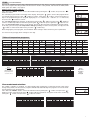
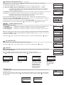
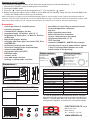
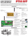
ROOM THERMOSTAT
WITH GSM MODULE
PT32 GST
A sophisticated thermostat which can be remotely controlled by means of SMS messages from your mobile phone.
The thermostat includes two devices, temperature controller and GSM module, which co-operate, thus increasing the comfort
of the heating system control. Simple control elements are used for setting; intuitive navigation in the selected language
(CZ/PL/EN/DE/RU/SVK). Remote control is executed by means of brief SMSs which enable you, for example, to change the
required temperature or turn off the system. This unique thermostat with a big backlit display and intelligent PID-control offers
a wide variety of usage in residential houses, offices as well as recreation areas.
DESCRIPTION
The GSM aerial is included in the
packing (can be replaced by
GST type – external
an external one
9 dBm, SMA connector
with higher sensitivity).
(not included in the
packing); can be
purchased separately,
order No. 1330,
on www.elbock.cz.
Backlit display
After you press any button,
the display is backlit automatically
for at least 5 s.
Controls
turning
short press
= change of temperature setting
= selection (entry) confirmation
= rquick change of required
temperature or program (see page 8);
viewing other information (see page 8)
= step back (only in the CONST mode,
see page 5)
long press
press
= opening the main menu or returning
a step back
Connector for power supply No. 1
for the AD05-jack power supply
(included in the packing)
SIM card holder
space for inserting the SIM card
(the SIM card is not included in the
packing)
Connector for external sensor
can be used with sensors CT04-10k
(order No. 0012), CT01-10k (order No.
0015) or CT02-10k (order No. 0013)
Connector for power supply No. 2
for power source installed in a wiring
box (not included in the packing)
Backup batteries room
to backup the time running, always use
rechargeable batteries of the AA/R6
type (not included in the packing)
Type AD05-jack
5V/ DC, 2.5 A
Open the SIM card
holder and insert the
SIM card in the direction
indicated; then close the
holder again.
Type CT04-10k
silicone conductor, length
3 m for measurements
up to 99 °C, including
connector
Use the type:
5V / DC, 2,5 A
(SELV)
MIND THE
POLARITY!!
+5 V 0 V
LCD DESCRIPTION
6
7
9
8 10 11 12
5
4
13
3
14
2
1
15
16
17
18
1. Current day (in the Prog mode,
selection of days to be
programmed)
2. Heating on indication
3. Current room temperature
4. Anti-freeze temperature
5. Modes for setting programs
(PROG) and constants (CONST)
(page 4 and 5)
6. Automatic mode (page 3)
7. Manual mode (page 3)
8. Clock setting mode (page 3)
9. Holiday mode (page 3)
10. Permanent shut-off (page 3)
11. Summer mode (page 6)
12. Boiler inspection indication
(page 8)
13. External sensor connection
indication (see page 7)
14. Current time
15. Current date (various parameters
in the CONST mode; for details,
see page 5)
16. Status line, dynamically changing
according to the process running
17. Key lock indication (page 8)
18. Low battery indication
1
INSTALLATION
Install the thermostat at a suitable place where its operation will not be affected by direct flow of hot air from a heating source, by sunshine or
other disturbing effects. Do not install it on an external wall either. The installation height should be at least 1.5 m above the ground. Locate the
thermostat in the so-called reference room, such as the living room (the heat source will be switched according to the temperature in this room).
The installation and battery replacement can only be done by a person with adequate qualification!
Before installation, disconnect the power supply!
1)
2)
3)
4)
5)
6)
7)
8)
9)
10)
11)
Switch off the main circuit breaker.
Remove the control part from the bottom cover of the device (Fig. 1).
Chip off the plastic piece in the middle of the bottom cover to lead in the conductors.
Run the conductors through the hole and connect them to the terminal board, see the wiring diagram.
Fasten the bottom cover to the wiring box by means of screws (Fig. 2).
Insert the activated SIM card into the SIM card holder at the back of the control part.
If you want to back up the time, install the fully charged rechargeable batteries (see Fig. 3).
Mount the control part onto the bottom cover (Fig. 2).
Connect the power supply to the connector No. 1 or No. 2 (see page 1). ATTENTION PT32 GST MUST BE POWERED FROM ONE SOURCE!!
Switch on the main circuit breaker and test the thermostat for correct connection, see page 3 (TEST).
Upon the first start (or reset), the thermostat shows the “SET CLOCK”, “ENTER PIN” messages; set the current time and date
acc. to the instructions on page 3, enter the PIN acc. to page 7 and select language acc page 5.
Fig.1
Fig.3
The thermostat enables backup of time in
case of power failure. You must use rechargeable batteries 2x1,2 V, type AA/R6. After
power failure, the time remains current (approximate service life: 2 years, according to
the type of batteries used).
The advantage is recharging of the batteries
after the power supply is restored.
AA rechargeable
battery
CAUTION: THE BATTERIES ARE NOT USED
FOR SUPPLYING THE THERMOSTAT, FOR
WHICH THE AD05-jack POWER SOURCE
MUST BE USED (see page 1).
AA rechargeable
battery
Fig.2
Wiring diagram:
BOILER
PT32GST
connector for the
AD05 power source
connection
COM
potential-free
(voltage-free) contact
NO
*
* The thermostat terminals are
marked differently with every
boiler type; therefore, observe the
wiring recommended by the boiler
manufacturer!
MENU
FIRST SWITCH-ON
After you switch on PT32GST first, the following message appears on the LCD; follow the instructions to make the corresponding settings
(INSERT SIM CARD BEFORE POWER CONNECTION):
Press the “ MENU “, button twice;
choose the CLOCK mode by
turning the “
„ button and make
the settings acc. to page 3.
TEST GSM
SET TIME
SET TIME
SET HOUR
CONSTANTS
13 ENTER PIN
GSM module is being
checked.
Press the “ MENU “, button twice;
choose the CONST mode by
„ button; move on
turning the “
to set CONST13 acc. to page 7.
ENTER PIN
2
OPERATING MODES
Pressing any button first, you activate the display backlit. By another short press of the “ MENU “ button, you open the main menu in which
you can choose operating modes.
AUTO
(the Pr3 weekly program set by default, see page 4)
The thermostat works according to the weekly program settings (this program can be changed; for detailed
description, see PROG, page 4).
Press twice the “ MENU “, choose the AUTO mode by turning the “ “ and press the “ “ button to confirm.
SMS form: Auto
Change of the mode to AUTO. Thermostat will be work acc. last setting weekly program.
AUTO MOdE
MANU (default temperature setting of 21°C)
The thermostat works according to the temperature setting until the next manual change.
Press twice the “ MENU “, choose the MANU mode by turning the “ “ and press the “ “ button to confirm.
“.
SMS form: Manu
Change of the mode to MANU. Thermostat will be keep last setting temperature.
MANU MOdE
(the anti-freeze temperature of 3 °C is kept – cannot be changed)
OFF
The thermostat is permanently switched off until the next manual change of the mode.
Press twice the “ MENU “, choose the OFF mode by turning the “ “ and press the “ “ button to confirm.
SMS form: Off
Change of the mode to OFF. You can cancel the mode by the SMS: Temp xx or Auto or Manu
OFF MOdE
HOLIDAY
The thermostat maintains the preset temperature until the preset date and selected time. After expiry of the
preset period, it automatically returns to the AUTO/ MANU mode last selected before the holiday.
Press twice the “ MENU “ button, choose the
mode by turning the “
“ and press the “
“ button to
confirm.
Step by step, set the temperature which the thermostat should keep during the holiday, date and time of your
return from the holiday. Change the values by turning the “ “ button and confirm each change by pressing
the “ “ button.
After making the settings, press the“ “ button to return to the basic screen.
HOLIdAY
Note: The holiday mode can be cancelled any time by selecting another AUTO or MANU mode.
SET TEMP
CLOCK SETTING
Setting the current time and date.
Press twice the “ MENU “ button, choose the CLOCK mode by turning the “ “ button, and press the
“ “ button to confirm.
Change the values by turning the “ “ button and confirm each change by pressing the “
“ button (the
parameter modified is always flashing); pressing the “ “ button, you return to the menu).
(PROGRAMMING)
You can set 9 weekly programs with 6 temperature changes per day. The Pr1 and Pr2 programs are empty;
Pr3 to Pr7 programs are set by default. The PrU and PrL are also set by default, intended for the EVEN/ODD
week option (for details, see pages 4 and 6).
PROG
SET TIME
SET HOUR
PROGRAMMING
CONST (CONSTANTS)
Setting the control parameters. For a detailed description, see page 5.
Press twice the “ MENU “ button, choose the CONST mode by turning the “
“ “ button to confirm.
“ button, and press the
CONSTANTS
TEST
Testing the correct connection to boiler.
“ button
Press twice the “ MENU “, choose the TEST mode by turning the “ “ button, and press the “
to confirm (RELAY TEST is showed on LCD). Turn the “ “ button to start testing. The output relay will be
switched on/off several times (the ON/OFF messages appear on the LCD).
ON
TEST MOdE
OFF
3
PROG (PROGRAMMING)
You can set 9 weekly programs with 6 temperature changes per day. The Pr1 and Pr2 programs are empty;
Pr3 to Pr7 programs are set by default. The PrU and PrL are also set by default, intended for the EVEN/ODD
week option (for details, see page 6).
Change in the program settings:
“
Press twice the “ MENU “ button, choose the PROG mode by turning the “ “ button, and press the “
button to confirm.
The selected program number is flashing on the display. Turning the “ “ button, choose the program which
you want to change and press the “
“ button to confirm. Turning the “ “ button, choose the number of
days to be programmed (you can program day-by-day or 1-5 = Mon-Fri, 6-7 = Sat-Sun, or 1-7 = Mon-Sun)
and press the “ “ button to confirm.
The 1st change time starts flashing; set the time by turning the “ “ button and press the “
“ button to
confirm. Set the temperature for this time by turning the “ “ button and press again the “ “button to confirm. The 2nd change time appears on the display. Proceed in the same way as with the first change setting.
In this way, you can set up to 6 temperature changes per day. To return one step back, shortly press the
“ “ button; to return to the main menu, press the “ “ button long.
After changing the preset program, check whether all the changes made conform to your requirements!
PROGRAMMING
SELECT PROGRAM
SELECT dAY
It is not necessary to apply all six changes to one day!
TIME CHANGES
Tables of temperature programs:
program No.1
program No.2
Monday
Tuesday
Wednesday
Thursday
Friday
Saturday
Sunday
Monday
Tuesday
Wednesday
Thursday
Friday
Saturday
Sunday
program No.3
program No.4
program No.5
Monday
Tuesday
Wednesday
Thursday
Friday
Saturday
Sunday
Monday
Tuesday
Wednesday
Thursday
Friday
Saturday
Sunday
Monday
Tuesday
Wednesday
Thursday
Friday
Saturday
Sunday
Note:
5/21 means
that the required
temperature at 5
o’clock is 21 °C
program No.6
program No.7
Monday
Tuesday
Wednesday
Thursday
Friday
Saturday
Sunday
Monday
Tuesday
Wednesday
Thursday
Friday
Saturday
Sunday
All the
indicated
programs
can be
changed!
Even or odd week selection:
This setting is suitable, for example, for shift operation (the requirements on thermal comfort in the object
change every week). The PrU and PrL programs will alternate automatically. The programs can also be modified according to your requirements.
Press twice the “ MENU “ button, choose the CONST mode by turning the “ “ button, and press the “ “
button to confirm. Repeat pressing the“ “ button until the constant No. 9 appears on the LCD. Set YES by
turning the “ “ button, and press the “ “ button to confirm.
U
Monday
Tuesday
Wednesday
Thursday
Friday
Saturday
Sunday
Odd-EVEN MOdE
L
Monday
Tuesday
Wednesday
Thursday
Friday
Saturday
Sunday
4
CONST (CONSTANTS)
Setting the control parameters.
“ button, and press the “
Press twice the “ MENU “ button, choose the CONST mode by turning the“
button to confirm.
“
CONSTANTS
1 ENGLISH (English language set by default)
Language selection (CZ/PL/EN/DE/RU/SVK).
Choose the language by turning the “ “ button and press the “
“ button to confirm.
2 MINIMUM CONTROL TEMPERATURE (5 °C set by default)
Setting the limit of the minimum temperature which can be set. If using the GSM module, you will be
informed by an SMS that the room temperature has dropped below this value (check CONST tEL nO,
page 7). Choose within the range from 3 °C to 10 °C (by 0.5 °C).
Set the value by turning the “
“ button and press the “
“ button to confirm.
TEMP.
3 MAXIMUM CONTROL TEMPERATURE (39 °C set by default)
Setting the limit of the maximum temperature which can be set. If using the GSM module, you will be
informed by an SMS that the room temperature has risen above this value (check CONST tEL nO,
page 7).Choose within the range from 15 °C to 39 °C (by 0.5 °C).
Set the value by turning the “
“ button and press the “
“ button to confirm.
TEMP.
4 CONTROL TYPE (PID control set by default)
Selection of the control type:
Choose the type of control by turning the “
“ button and press the “
“ button to confirm.
HS = Hysteresis
TYPE OF REGUL.
Difference between the desired and current temperature.
If the hysteresis is 1 °C and the desired temperature is 20 °C, the thermostat switches off at 20 °C, and on at 19 °C (see the graph).
For correct hysteresis function, set the parameters according to the heating system type; see CONST 5.
Note: If hysteresis is selected, CONST 6 is skipped automatically.
PI = proportional-integral control
The PI-control principle consists in comparison of the current room temperature with the desired temperature.
The PI-control aims at achieving and maintaining the desired temperature without overshooting (see the graph). For correct function of the
PI-control, set the control parameters according to the type of the heating system with respect to the room thermal inertia;
see CONST 6.
Note: If the PI-control is selected, CONST 5 is skipped automatically.
PID = proportional-integral-derivative control
The PID-control principle consists in continuous comparison of the current room temperature with the desired temperature,
and automatic adaptation of the controller to the given conditions.
This is the most perfect continuous control; you can achieve not only short control time, but also high accuracy without permanent control deviation. The minimum switch-on time is internally set to 2 minutes, the proportional band is 2 °C, the time interval is automatically
recalculated according to current temperature conditions.
Note: If the PID-control is selected, CONST 5 and CONST 6 are skipped automatically.
HYSTERESIS
PID-CONTROL
PI-CONTROL
T
T
T
požad.
teplota
požad.
teplota
pásmo
proporcionality
hystereze
t
t
Topení
ON
Topení
ON
t
požad.
teplota
t
Topení
ON
t
t
Note: The graphs are just tentative; the real control course differs according to current conditions in the measured object!
CAUTION! ONLY IN CASE OF LOCKING BY PASSWORD (see CONST19)
If the “
“ key symbol appears on the LCD, the constant selected cannot be modified and you must know the
PASSWORD (see CONST 19, page 8). You can change the constant after entering the password. After you exit the
CONST mode, the security lock of the constants related to the control will be activated automatically.
TYPE OF REGUL.
5
5 SETTING HYSTERESIS PARAMETERS
HYSTERESIS (factory setting of 0.5 °C)
Set from 0.1 to 6 °C. According to the value preset, the thermostat switches on at the temperature:
T switching = T required - HYSTERESIS
Set the hysteresis by turning the “
“ button, and confirm with the “
HYSTERESIS
“ button.
MINIMUM SWITCH-ON TIME (factory setting of 2 min)
Here you can set the minimum switch-on time of the boiler in minutes at hysteresis. Select within the
range from 1 to 5 minutes according to the type of the heating system used (see the table).
Set the value by turning the “
“ button, and confirm with the “
“ button.
MIN TIME ON
6 SETTING PI-CONTROL PARAMETERS
PI-CONTROL INTERVAL (factory setting of 10 min.)
Select according to the object’s thermal inertia. The optimum setting usually falls within the range of
10 to 15 min. The adjustable range is 5 min to 20 min (by 1 min).
Set the interval by turning the “ “ button, and confirm with the “ “ button.
MINIMUM SWITCH-ON TIME (factory setting of 2 min.)
Select within the range of 1 to 5 minutes. The setting is given by the
heating system type, and depends on the PI-control time period selection.
Setting according to the table is recommended.
Set the value by turning the “ “ button, and confirm with the “ “ button.
Heating type
Minimum source
switch-on time
Electric heating
Plate radiators
Cast iron radiators
Floor heating
1
2 (3)
4
5
PI-CONTROL BAND (factory setting of 2 °C)
TThis value determines the temperature at which the PI-control starts functioning. For example, the
desired temperature is 22 °C, the proportional band is 1.5 °C. Up to 20.5 °C, the source heats fully.
When this value is reached, the PI-control starts. The PROPORTIONAL band can be set within the
range of 0.5 to 3.0 °C (by 0.1 °C).
“ button, and confirm with the “
Set the PI band by turning the “
MIN TIME ON
PI ZONE
“ button.
7 PRELIMINARY SWITCH-ON OF HEATING (NO set by default)
This function guarantees you the required temperature at the required time. You need not consider when
to switch the heating on in order to be warm when getting up in the morning without heating unnecessarily
long in advance. You just program the time at which you want the desired temperature. Within two operating days, the program ascertains the thermal constants of the room and then it switches the heating on
in advance sufficiently. The preliminary switch-on time is limited to 2 hours.
Set YES/NO by turning the “ “ button and press the “ “ button to confirm.
PRE SWITCH MOdE
8 SUMMER MODE (NO set by default)
In this mode, you are not allowed to switch the heating on. It can particularly be used in the summer
period, when you need not heat. After you enable this mode, the “
“ symbol appears on the display.
Note: The anti-freeze protection (3 °C) is still enabled. In this mode, you cannot change the temperature
or set the holiday mode!
Set YES/NO by turning the “
“ button and press the “
“ button to confirm.
SUMMER MOdE
9 EVEN-ODD WEEK SELECTION (NO set by default)
If you choose “YES”, the PrU and PrL programs will alternate automatically according to the current week
(even/odd). This setting is suitable, for example, for shift operation (the requirements on thermal comfort
in the object change every week).
Set YES/NO by turning the “
“ button and press the “
“ button to confirm.
Odd-EVEN MOdE
10 HEATING / COOLING SELECTION (HEAT set by default)
Setting the thermostat function.
HEATING = the output relay (for heating systems) switches if the current temperature drops below the desired value
COOLING = the output relay (for cooling systems) switches if the current temperature rises above the desired value
Set HEAT/COOL by turning the “
“ button and press the “
11 TEMPERATURE CORRECTION
“ button to confirm.
(0 °C set by default)
This is used for correcting the temperature measured by the thermostat. The setting can only be done
after 12 hours of operation, when the internal sensor temperature has settled. Measure the room
temperature with a thermometer; if it is different from the temperature on the thermostat,
set the correction within the range of -5 °C do +5 °C.
Set the correction by turning the “
HEATING
“ button and press the “
TEMP CORRECT
“ button to confirm.
6
12 EXTERNAL SENSOR SELECTION
If an external sensor is connected, the
( - - - set by default)
symbol appears on the LCD (to approx. 20 minutes).
The external sensor can be used for:
1, control according to the room temperature - the sensor is located in the room ( - - - option)
2, control according to the floor temperature - the sensor is located in the floor (- - - option)
--If connected, the external sensor measures the temperature at the place of its installation
12 EXT SENSOR
(suitable, for example, for places at which the thermostat cannot be located, yet you want to
control according to this room);
3, maximum floor temperature monitoring - čthe sensor is located in the floor (selection of 15 to 99,5°C)
15…99,5°C If connected, the external sensor monitors the floor temperature; the maximum
temperature allowed for floor heating must be set (control according to the room
12 EXT SENSOR
temperature, with simultaneous floor temperature monitoring).
If the preset limit temperature is exceeded, the thermostat is switched off irrespective of the room
temperature, and the “EXT SENS STOP” message appears on the LCD. The heating device is switched
on again if the external sensor temperature drops by 0.5 °C.
If the external sensor is unconnected or faulty, the “EXT SENS ERROR” message appears on the LCD.
Set the external sensor option by turning the “
tEL nO
“ button and press the “
EXT SENS STOP
“ button to confirm.
PHONE NUMBER SETTING
Allows the following options:
1) TO SENdER
= SMS will be sent back to the telephone number from which the message was sent.
2) TO ANOTHER NR = SMS will be sent back to the telephone number entered in the thermostat.
3) bOTH NUMbERS = SMS will be sent back to both telephone numbers (combination options 1 and 2).
When choosing 2) and 3) option we enter a phone number n the international format (420123456789),
to which return SMS messages on the thermostat condition should be sent. Is possible to enter a phone
number min. 10-digit to 15-digit.
Turning the “
“ button, enter the phone number stepwise; confirm each setting with the “
TO SENdER
TO ANOTHER NR
“ button.
420000000000---
13 PIN CODE SETTING
Enter the PIN code of the SIM card inserted in the thermostat.
Turning the “
“ button, enter 4 digits stepwise; confirm each setting with the “
“ button.
13 ENTER PIN
14 GSM TEST
After setting the PIN code of the SIM card inserted in the thermostat is performed to test the GSM
module and PIN validation.
Turning the “ “ button to start test of GSM module and checking of PIN code.
The“ “ button displays the next constant,; pushing “ “ you return to the main menu.
INSERT SIM
Checking the
GSM module.
PIN entered
correctly.
SIM card not inserted. Insert the SIM
card, disconnect
power to the 5 s,
make adjustment
and repeat test.
14 GSM TEST
ERROR PIN
Wrong PIN.
Reset PT32GST
and enter PIN
again.
15 RELAY TEST
Testing the correct connection the thermostat to boiler (this function is identical with the TEST mode
in the main menu).
Start the test by turning the “ “ button. The output relay is switched on/off several times (the ON/OFF
messages appear on the LCD). The “ “ button displays the next constant; pushing “ “ you return to
the main menu.
ON
15 RELAY TEST
OFF
7
16 KEY LOCK (NO set by default)
This is used for locking the controls as a protection against undesirable interference of a foreign person.
Set YES/NO by turning the “
“ button and press the “
“ button to confirm.
16 LOCK
17 KEY CODE
This constant can be set if CONST 16 = YES. It is used for setting the code by which you will be able to
activate the controls. Set a four-digit combination (range from 0 to 9).
The keys will be locked within 1 minute (after opening the basic display). The “
” symbol appears on
“ or “
“ button, the LCD asks you to enter the key code; after entering
the LCD. If you press the “
the correct code, you are able to make any changes (the controls are functional again). The controls will
automatically be locked again after you finish the setting (within approx. 1 min).
Gradually set 4 digits by turning the “ “ button; confirm each setting with the “ “ button.
RECOMMENDATION:
- Record the key code in the table
- You can cancel the code by setting CONST 16 to NO, or by restoring the
default settings of the thermostat (see CONST 20).
18 BOILER INSPECTION REMINDER (1.1.2032 set by default)
Set the date on which you want to be informed about the necessity of the prescribed boiler service. At the
required time, the “MAINTENANCE NECESSARY” message and the “ ” symbol will appear on the bottom line of the LCD (you can cancel the message by setting a new date for the next boiler maintenance!).
Gradually set the day, month and year by turning the“ “ button, confirm each setting with the “ “.
19 PASSWORD (not set by default)
It is used for locking the constants related to the given control settings. Suitable for service technicians.
After a numerical code has been entered, the user cannot change constants No. 4, 5, 6 and 10.
If you open the CONST mode and browse the constants, the “ ” symbol appears next to the constants
locked; if you turn the “ “ button, the password is required! Unless you enter the password, the constants remain locked. To try to unlock them again, you must exit the CONST mode and browse up the
constant locked again.
Turning the “ “ button, gradually enter four digits and confirm each setting with the “ “.
17 KEYCOdE
YOUR CODE
18 SERVICE dAY
19 PASSWORd
20 VERSION (restoring the default settings)
Firmware version, informative parameter only.
“ button long (for about 3 s), the RESET message appears shortly on the LCD and
If you press the “
the thermostat returns to the default settings!
20 VERSION
USER TIPS
QUICK CHANGE OF REQUIRED TEMPERATURE / PROGRAM IN THE AUTO MODE
Press twice the “ “ ; the required temperature starts flashing on the display. Change the required temperature by turning the “ “ button and press the “ “. The change will last until the next program change.
SMS form: Temp xx (where xx are only integers within the range of CONST2 and CONST3)
Change of the desired temperature; the change will last until the next temperature change given
by the program.
Press thrice“ “, the setting programm starts flashing on the display. Change it by turning “
button and press the “ “.
“
TEMP. IN AUTO
QUICK CHANGE OF REQUIRED TEMPERATURE IN THE MANU MODE
Press twice the “ “; the required temperature starts flashing on the display. Change the required temperature by turning the “ “ button and press the “ “. The change will last until the next manual temperature
change.
SMS form: Temp xx (where xx are only integers within the range of CONST2 and CONST3)
Change of the desired temperature; the change will be permanent.
TEMP IN MANU
OPERATIONAL HOURS
Push the “
“ button four times. The boiler operating hours appear on the LCD. The figure on the picture
means 906 hours 43 minutes.
Resetting the counter:
When operational hours are displayed, turn the “ “ button anti-clockwise.
OPER HOURS H.C.
EXTERNAL SENSOR TEMPERATURE
Push the “
“ button five times. The current temperature of the external sensor appears on the LCD; the
value is only informative, and appears only if the external sensor is monitoring the maximum floor temperature
(see CONST 12, page 7).
TEMP 2Nd SENS
8
INFORMATION IN THE LCD DYNAMIC LINE
SIGNAL GSM x
Determines the signal strength at the place where the thermostat is located;
where x is a value within the range from 0 to 5:
0..undeterminable or no signal detected
1..worst level
5..best level of signal
Information on the desired temperature preset
REQUIR TEMP
PROGR 3 PERIOd 2
SMS RECEIVEd
HOLIdAY IN 22.7
T EXT SENS 25.0
EXT SENS STOP
Information on the program preset (e.g., 3) and the time interval running
(interval 2)
Information the thermostat received new SMS
Only displayed in the holiday mode; informs on the end of holiday when the
thermostat restores the last selected AUTO/MANU mode.
Current temperature of the external sensor, displayed only if the sensor is
connected
If the preset limit temperature of the external sensor in the maximum floor
temperature monitoring function is exceeded (see page 7), the thermostat is
switched off
FORMS OF MESSAGES SENT
Info
Auto
Information on the heating system status
Setting AUTO mode, thermostat will be work acc. last setting weekly program
Manu
Setting MANU mode, thermostat will be keep last setting temperature
Off
Heating system switched off permanently. ; to cancel the function, use the
Temp xx message, thermostat will automatically enter into the MANU mode with the
given temperature or SMS message Auto (for AUTO mode) or Manu (for MANU)
Required temperature change (only integer numbers can be entered, they must fall
within the permitted range of maximum and minimum temperatures –CONST2 and
CONST3).
Back call
Temp xx
Call
xx = temperature value in °C (always a two-digit number, e.g. 05)
!
Any type of mobile phone can be used for sending and receiving back messages!
If you can set the font size (format) in your phone, always use the MEDIUM size when writing messages
(if there are three options), or the BIG size (if there are two options).
FORMS OF BACK MESSAGES FROM THE THERMOSTAT
Requir: xx.x
Act: xx.x
Set on
Set off
AUTO
MANU
OFF
Sig: x
Sens 2: xx.x
Battery!
Noakcept!
Temperature required (user set)
Current room temperature
Heating system On
Heating system Off
Thermostat in automatic AUTO mode
Thermostat in manual MANU mode
Thermostat in the OFF mode (permanently off)
Signal strength at the place where the module is located; where x is the
value within the range of 0 to 5:
0..undeterminable or no signal detected
1..the worst strength
5..the best signal strength
Current temperature of the external sensor
Low batteries in the thermostat
Error indicated (wrong SMS format, etc.)
xx.x = temperature value in °C
BACK MESSAGES ARE SENT WITHIN 3 MINUTES!
Note: If the minimum / maximum room temperature (preset CONST 2 and 3) is exceeded, the “WARNING” SMS is
automatically sent in a form similar to that in the „Info“ form (only if you enter phone number to the thermostat, see CONST tEL nO).
Info: If using a credit card, you must make a paid call once in 3 months. This call is executed automatically (in 80 days, between 4 and 9
PM) to the phone number entered in the thermostat (CONST tEL nO); after 20 s, the call is terminated automatically. You can execute this
function earlier by means of the “Call” SMS message.
9
Example of using PT32GST:
The thermostat is located in a room where anti-freeze temperature must be maintained (e.g., 7 °C).
1. Connect the PT32GST strictly according to the instructions.
2. Choose the MANU mode.
3. Press the “ “ button and set the temperature of 7 °C by turning the “ “ button.
4. Before arriving at the object, write an SMS in your mobile with the wording: Temp 23; then send the SMS to the
number of the SIM card inserted in your thermostat.
After receiving the message, the thermostat automatically switches on the heating system until the desired temperature is
reached. Then PT32GST automatically sends the “BACK SMS message” informing you about the temperature change made.
After arriving at the object, you can change the temperature according to your needs on the thermostat directly.
Properties:
4
4
4
4
4
4
4
4
4
4
4
4
4
4
4
control by means of a mobile phone
4 possibility of connecting an external sensor
4 current temperature correction
9 weekly programs
4 key lock
6 temperature changes per day
4 boiler operating hours total
programming by 10 minutes and 0.5 °C
programming “day-by-day” or Mon-Fri, Sat-Sun 4 boiler maintenance indication
4 service safeguard by a password
or Mon-Sun
4 anti-freeze protection (3 °C)
big backlit graphic display
selection from three types of control: PID, PI or 4 TEST function
4 automatic SUMMER / WINTER time change
HYSTERESIS
4 clock backup in case of power failure, approx.
preliminary heating start function
7 days if rechargeable batteries are used
short-term change in the required temp.
(not included in the packing)
manual mode (MANU)
permanent switch-off (OFF)
Power source:
External sensor:
HOLIDAY mode
not included in the
summer mode
included in the
packing type CT04-10k,
packing
even-odd week selection
CYXY 2 x 0.5 mm,
type AD05-Jack,
heating / cooling mode selection
10 kΩ, lenght 3 m,
5V/ DC, 2.5 A
plastic case PVC
Dimensions:
(CT01-10k and CT02-10k
sensors can also be used)
83
Technical parameters
28.5
136.5
CERTIFICATE OF GUARANTEE
(guarantee period for the product amounts to 2 years)
product No.:
date of sale:
stamp of shop:
examined by:
Power supply
GSM module
Aerial
Number of adjustable temp.
Hysteresis
Minimum program. time
Adjustable temperature range
Temperature setting
Minimum indication step
Measurement accuracy
Protection
Protection class
Output
Working temperature
5 V/ DC, 2.5 A, type AD05 - Jack
SIM 900
direct 1dB
6 different temp. per every day
0.1 to 6°C
10 minutes
+3°C to 39°C
by 0.5°C
0.1°C
± 0,5°C
IP20
II
max.5 A (potential-free contacts)
0°C to +40°C
In case of guarantee or post-guarantee service, send the
thermostat including proof of purchase to the manufacturer’s
address. The guarantee does not cover faults resulting from
incompetent installation or interference in the device design.
ELEKTROBOCK CZ s.r.o.
Blanenská 1763
Kuřim 664 34
Tel.: +420 541 230 216
Pb
LEAD FREE
in compliance with RoHS
MADE IN CZECH REPUBLIC
www.elbock.cz
10