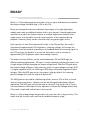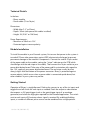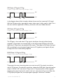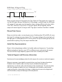
1
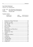
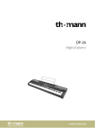
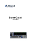
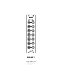
!
!
BINARY
User Manual
Version 1.0
BINARY
Binary is a 1-bit analog computer that takes up to six inputs and determines whether
the output voltage should be high (+5V) or low (0V).
Binary was designed to take the individual step outputs of a single Algorhythm
module and create an additional pattern with its own controls. Another application
would be to combine the Pattern outputs of multiple Algorhythm modules into a
single stream, with the ability to mute certain portions of the sequence during
playback. However, Binary can be used with nearly any gate/trigger source.
Each input has its own illuminated on/off switch. In the ON position, the switch is
illuminated at approximately 50% brightness. Incoming voltages will increase the
brightness from this baseline, providing visual feedback about the incoming signal. In
the OFF position, the baseline is to have no illumination, with an increase to
approximately 50% brightness when input voltage increases.
The output circuitry of Binary can be switched between OR and NOR logic for
different patching applications. OR logic is used to combine multiple pulse inputs into
a single output (without changing the output voltage level). With the OR gate active,
the output voltage of Binary is high when any of the six input voltages are high. NOR
is a logical negation of OR, so switching to NOR logic will provide negation of input
voltages. With the NOR gate active, the output is high by default. An incoming
positive voltage will cause the output to drop to 0V.
The NOR gate can be used for sidechaining effects, where a VCA or filter is closed
when a timing event occurs. Upbeats can also be changed to downbeats without
repatching. The NOR gate can also be used to convert S-Trig signals into V-Trig (or
vice-versa) because the output circuitry operates in the positive voltage domain only.
(This patch is explained in detail later in the manual.)
Binary is a fully-analog design that primarily uses transistors for its logic circuitry. This
means that the circuitry works well into the audible frequency range.
Version 1.0 (2014-02-25)
2
Technical Details
In the box:
- Binary module
- Power cable (10-to-16 pin)
Dimensions:
- Width: 6hp (1.2” or 30mm)
- Depth: 30mm (with power/link cables installed)
- Height: 3U (5.06” or 128.5mm)
Power Requirements:
- Maximum of 30mA at +12V
- Protected against reverse polarity
Module Installation
To install the module in your Eurorack system, first ensure that power to the system is
turned off. Please take precautions against ESD (electrostatic discharge) to prevent
permanent damage to the module’s components. Connect the smaller 10-pin socket
of the power cable to the module, noting the “stripe” indicator on the PCB (which
should align with the red stripe on the cable). Then connect the 16-pin socket to your
power distribution board. Take note of the power cable’s orientation with regard to
the -12V supply of your power distribution board. The red stripe usually (but not
always) aligns with the bottom of the power connector. Binary is protected against
reverse polarity (which occurs when a power cable is connected upside down) but
other modules in your system may not be.
Getting Started
Operation of Binary is straightforward. Patch pulse sources to any of the six inputs and
toggle the on/off switch for each input as needed. Patch the output to a destination
that expects a +5V gate/trigger (such as the gate/trigger input of an envelope
generator) and select the logic gate required for the intended application. The switch
next to each input will illuminate when a signal is received. By enabling/disabling
inputs, a number of different pulse sources can be combined into a single pattern.
Version 1.0 (2014-02-25)
3
LOGIC OUT Jack and OR/NOR Switch
The Logic Out jack reflects the result of
the chosen logic gate. Its output is a
positive-going pulse (+5V).
The OR/NOR Switch controls the logic
gate used for the computation. When
illuminated, the OR gate is active. When
not illuminated, the NOR gate is active.
Input Jacks and ON/OFF Switches
Each of the six input jacks has its own
latching ON/OFF switch.
The ON state is latched (pressed down),
the OFF state is unlatched. In the ON
state, the baseline illumination of the
switch is ~50%. Incoming signals increase
the illumination of the switch to indicate
activity at that input.
In the OFF state, the switch is not
illuminated, but incoming signals increase
the illumination level to ~50% to provide
visual feedback about the status of
muted inputs.
Version 1.0 (2014-02-25)
4
Truth Tables
Boolean logic gates can be visualized with truth tables. These tables usually take two
inputs and compute one output. With Binary, there are six possible inputs, but the
fundamental principle remains the same.
OR GATE
NOR GATE
Input 1
Input 2
Output
Input 1
Input 2
Output
0
0
0
0
0
1
1
0
1
1
0
0
0
1
1
0
1
0
1
1
1
1
1
0
The OR Gate remains low (0) when all inputs are low, and goes high (1) when at least
one input is high. The NOR Gate remains high when all inputs are low, and goes low
when at least one input is high. In the truth tables above, 0 represents 0V and 1
represents +5V.
S-Trig and V-Trig Conversion
The gate/trigger inputs on most synths, drum machines, and sequencers are activated
by a rising voltage (such as 0>5V). This is commonly called a V-Trig circuit. But some
devices use a different circuit called an S-Trig (or shorting trigger), in which the circuit
rests at a positive voltage and responds when the voltage drops to 0V.
Converting between these two standards is not as simple as inverting the voltage.
Passing a 0>5V gate signal through an inverter circuit will result in a voltage that jumps
from 0V to -5V when active. Since most gate inputs expect a 0>5V pulse, an inverted
gate is not generally usable as a logic signal. A positive offset is still needed to create
a pulse that activates the logic circuits used by most modular synths.
Binary is designed for logic signals in the positive (0V>5V) range only, so it can be
used for conversion of S-Trig signals to V-Trig and vice-versa, without the need for the
additional offset. This applies to drum machines and sequencers as well as “note on/
off” events generated by (or required by) some analog synths.
Version 1.0 (2014-02-25)
5
OR Gate: V-Trig to V-Trig
Output is high when incoming voltage is high
5V
0V
In the diagram above, black triangles indicate the onset of an incoming 0>5V signal.
With the OR gate active, input equals output: when input is high, output is high. This is
the most common application of Binary, and works with most modern devices.
OR Gate: S-Trig to S-Trig
Output is low when incoming voltage is low
5V
0V
The OR gate is also used when S-Trig signals should pass through without being
negated. S-Trig outputs are normally high, so the logic output of Binary will remain
high when S-Trig sources are patched to the inputs. The output will fall when the input
falls, correlating to an active gate/trigger from an S-Trig device, and signals will pass
through the circuit without being negated.
NOR Gate: V-Trig to S-Trig
Output is low when incoming voltage is high
5V
0V
Things get a bit more interesting when you want to send V-Trig signals to a device
with an S-Trig input. To make this conversion, choose the NOR gate. Now the baseline
output is 5V (the “off” state of an S-Trig circuit). V-Trig input pulses will be negated,
dropping the output level to 0V, which is the “on” state of an S-Trig circuit. When the
V-Trig input pulse goes low, the output goes high again. No offset is needed.
Version 1.0 (2014-02-25)
6
NOR Gate: S-Trig to V-Trig
Output is high when incoming voltage is low
5V
0V
Binary can also convert S-Trig signals to V-Trig. Patch an S-Trig signals to an input and
use the NOR gate. Because the baseline S-Trig voltage is normally high, the NOR gate
will negate this logic and cause the baseline output voltage of Binary to be low (which
is the “off” state of a V-Trig circuit). S-Trig input signals will be negated, and the
output will remain high for as long as the S-Trig input is held low. No offset is needed.
Manual Gate Source
Binary can also be used as a manual gate source. Switching from OR to NOR will cause
the Logic Out voltage to increase from 0>5V. The output voltage will remain high until
the logic gate is switched back to OR. For this patch, the inputs would typically not be
connected to anything. Only the output would be used.
Audio Rate Experimentation
Binary’s fully-analog design enables it to handle audio-rate frequencies. Try patching
different waveforms from the same VCO to different inputs and monitor the output.
The result will be a high-frequency square wave with a variable pulse width.
Technical Support and Warranty Information
Send an email to [email protected] with requests for service or technical support.
Warranty coverage is provided for a period of one year from the date of purchase.
Problems with a module under warranty may be remedied through repair,
replacement, or refund, at the sole discretion of the manufacturer. The warranty does
not cover damage caused by the user, including but not limited to system power
supply malfunction, electrostatic discharge, introduction of excessive voltage levels
into the module, or physical damage to the components.
Version 1.0 (2014-02-25)
7