1
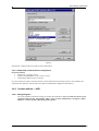
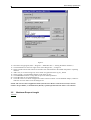
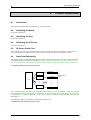
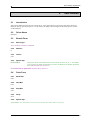
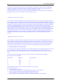
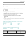
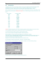
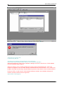
Citect for Windows Driver Specification Sseven Driver Author Date Comment Sean Ju 12/12/96 Original Sean Ju 3/11/97 Add/Modify Sean Ju 25/2/98 Add/Modify Sean Ju 30/7/98 Add/Modify Sean Ju 24/3/99 Add/Modify Trevor Hudson 24/3/99 Basic Testing Paul Nguyen 14/11/2003 New ini parameters added Driver Design Specification Contents 1. 2. INTRODUCTION 1.1 Scope. 5 1.2 Outline. 5 QA 2.1 3. 5 6 Developers Guidelines 6 2.1.1 Accredited Drivers. 6 2.1.2 Independent Drivers. 6 2.2 6 Accreditation process 7 TARGET DEVICE(S) AND PROTOCOL 8 3.1 Introduction 8 3.2 Device Manufacturer 8 3.3 Device Definition 8 3.4 Communications Method 8 3.4.1 Comms method ---- Profibus (Sinec L2) 3.4.1.1 Wiring Diagrams 8 8 3.4.1.2 Installing the communications processor (software setup sample for s7 library prior to version 4.1.xx) 8 3.4.13 CP5412 communications configuration steps 8 3.4.1.4 CP342-5 DP communications configuration 10 3.4.2 Comms method ---- MPI 3.4.2.1 Wiring Diagrams 10 10 3.4.2.2 Installing the communications processor (software setup sample for s7 library prior to version 4.1.xx) 3.4.2.3 CP5412 communications configuration steps 3.4.3 Comms method ---- TCP/IP 3.4.3.1 Wiring Diagrams 11 11 12 12 3.4.3.2 Installing the NE2000 network card (softare setup sample for S7 TCPIP library version 4.1.xx) 12 3.4.3.3 NE2000 card configuration steps 12 3.4.3.4 S7 communications configuration steps 13 3.5 Maximum Request Length S7NT.doc 14 2 Driver Design Specification 4. 5. PROTOCOL REQUIREMENTS 15 4.1 Introduction 15 4.2 Initialising the Board 15 4.3 Initialising the Port 15 4.4 Initialising the IO Device 15 4.5 IO Device Online Test 15 4.6 State Flow Description 15 4.7 Message Structure 17 4.8 Data Format 17 4.9 Error Handling 17 USER INTERFACE 18 5.1 Introduction 18 5.2 Driver Name 18 5.3 Boards Form 18 5.3.1 Board Type 18 5.3.2 Address 18 5.3.3 IO Port 18 5.3.4 Special Opt 18 5.4 Ports Form 18 5.4.1 Baud Rate 18 5.4.2 Data Bits 18 5.4.3 Stop Bits 18 5.4.4 Parity 18 5.4.5 Special Opt 18 5.5 IO Devices Form 19 5.5.1 Protocol 19 5.5.2 Address 19 5.6 Pulldown lists Help 19 5.7 IO Device Variable Types 20 5.8 Dbase Files 21 5.8.1 SSEVEN.DBF 21 5.8.2 22 5.9 PROTDIR.DBF Parameters and INI options 5.9.1 22 Standard Parameters 22 5.10 Driver Specific Errors 23 5.11 Stats Special Counters 24 5.12 Debug Messages 26 5.13 Hints and Tips 26 S7NT.doc 3 Driver Design Specification 6. 7. 8. BASIC TESTING 30 6.1 Introduction 30 6.2 Procedure 30 PERFORMANCE TESTING 35 7.1 Introduction 35 7.2 Calculating the Blocking Constant 35 REFERENCES 36 8.1 References 36 8.2 Contacts 36 S7NT.doc 4 Driver Design Specification 1. 1.1 Introduction Scope. This document follows the development of the new driver. It serves as a functional specification, design specification and test specification. 1.2 Outline. The specification is broken down into the following sections: Section 1 - Introduction. This section defines the scope of a board driver specification and outlines the items addressed by the specification. Section 2 - Quality Assurance. The QA section defines the requirements and procedures for Quality Assurance Accreditation. It is important you read this if you want your driver integrated into Citect. Section 3 - Physical Communication Method. The Physical Communication Method section defines the physical communication method supported, hardware/software suppliers, how the method is setup, any wiring diagrams involved etc. Section 4 - Protocol Requirements. The Protocol Requirements section details the technical considerations required or incorporated by the driver. Section 5 - User Interface. The User Interface section defines how the user will see and setup the driver in Citect. Section 6 - Basic Testing. The Basic Testing section defines the items which should be addressed in Basic testing by the developer. Section 7 - Performance Testing. The Performance Testing section is used in full testing of the driver by the Citect Testing Department of CiT. Once complete, this will provide details on the reliability and stability of the driver, and point out where the driver needs to be improved. Section 8 - References and Contacts. The References and Contacts section should be used as a record of reference materials and contacts used in developing this driver. S7NT.doc 5 Driver Design Specification 2. 2.1 QA Developers Guidelines These guidelines are meant as a rough indication of what options there are for developing Citect drivers and the advantages of these options. It is not a technical discussion of options, rather a marketing guideline. Drivers fall into two categories, Accredited and Independent. 2.1.1 Accredited Drivers. Accredited drivers are those drivers that have been put through the CiT Driver QA Scheme and have passed all stages of this accreditation process. It is a precondition to becoming accredited that these drivers will be included with Citect in a normal release. Accreditation has the following advantages: 1 The driver will be included in the product and a certificate stating this driver has achieved Accreditation will be sent to the developer. 2 Accredited drivers will be honoured as part of the product in terms of Citect Support and receive full cooperation between Citect Support personnel and the developer. On the other hand, independent driver problems will immediately be referred on to the original developer. 3 Help documentation and Express Wizards is provided, free of charge, for all Accredited drivers. Help documentation for Independent drivers is the responsibility of the developer. 4 Accreditation is included in the cost of the DDK. A high level of quality is expected and if this is not met the driver will not be Accredited. 5 Citect Customers see value in Accredited drivers as there is some assurance that the driver will operate as documented. Some customers may only accept Accredited drivers. 2.1.2 Independent Drivers. Independent drivers are those that have not completed or are not intended to complete the Accreditation process. These drivers will not be included in Citect, nor will they be given any support by Citect Support personnel. We would request all drivers be sent to CiT regardless, even if they are not to be included in the product. If this is done, we can try to ensure compatibility with future versions of Citect. Independent Drivers have the following advantages: 1 Drivers may be written by or for an end user giving them an edge over their opposition by using Citect. 2 Drivers may be developed as part of a package offered by System Integrators or including pre-configured packages etc., thereby maintaining the intellectual and financial investment. This would be similar to value added or OEM style marketing. 2.2 S7NT.doc 6 Driver Design Specification Accreditation process The following check list defines the QA steps for generating a new driver. This procedure must be followed for drivers to be integrated into Citect. It is advisable to ensure that items before each checkpoint are complete before proceeding to avoid rework if changes are required. Description Person Date 1 This specification document is written. Sean Ju 12/12/96 2 Specification reviewed and accepted by CiT Driver Development. At this checkpoint coding is ready to be commenced. 3 Driver coded. 4 Code and specification reviewed and accepted by CiT Driver Development. 5 Testing with connection project, and performance test. 6 Driver integrated into Citect source and built. 7 Documentation is written. 8 Documentation reviewed. At this checkpoint coding is done and the driver is available as a beta. 9a Full testing is carried out. Trevor Hudson 9/4/99 9b Performance testing is carried out. Trevor Hudson 9/4/99 9c Specification and documentation updated from testing/performance tests At this checkpoint the testing is complete. 10a Review for completeness by developer, tester, documenter and CiT Driver Development 10b Add driver to install disks 10c Add driver to drivers database 10d Support notified of new driver for training purposes 11 Sales notified of new driver The driver is now finished. The hand over of a driver requires that all the above steps are completed and checked off. S7NT.doc 7 Driver Design Specification 3. 3.1 Target Device(s) and Protocol Introduction This section defines the types of I/O Devices that are targeted by this driver. 3.2 Device Manufacturer Siemens 3.3 Device Definition S7 - 300 PLCs and S7- 400 PLCs 3.4 Communications Method This protocol talks to Siemens S7-300 PLC and S7-400 PLC via Profibus communication module (eg. S7 342-5 DP module) or TCP/IP communication module (eg. CP 343 – 1 TCP module) or directly to MPI port on the CPU module. Operating system required are Microsoft Windows 95 or Microsoft Windows NT 4.0 (service pack 3 applied). 3.4.1 Comms method ---- Profibus (Sinec L2) Note: “PROFIBUS” and “SINEC L2” are the same, they are interchangeable. 3.4.1.1 Wiring Diagrams All wiring should be installed according to Siemens documentation. PROFIBUS port On CP342-5 module Citect CP5412 A2 IBM Compatible S7 300/400 PLC S7 300/400 PLC S7 300/400 PLC S7 300/400 PLC 3.4.1.2 Installing the communications processor Software required to setup CP5412 A2 card • SINEC S7-5412 for Windows 95 (S7_5412/95) or Windows NT (S7_5412/NT) protocol libraries v4.1.xx • Authorisation disk. The installation tool shipped with the Library software is a Windows program that helps install the drivers and define some important parameters for both software (the library) and hardware (the CP5412 A2 card). 3.4.13 CP5412 communications configuration steps 1. Start Sinec setup program (Start -> Programs -> SIMATIC NET -> COM S7) 2. Select File -> New or File -> Open DB S7NT.doc 8 Driver Design Specification 3. Fill in the dialogue box, see figure 1 bellow. 4. Save the configuration (File -> Save or File -> Save as). 5. Generate Binary DB (File -> Generate Binary DB as) 6. Exit (File -> Exit) Note. • The connection names in the connection name list will be used in CITECT IODevice form, Address field. CASE sensitive. • The VFD names will be used in CITECT Ports form, Opt field. CASE sensitive. • Use siemens suggested value for the local TSAP (F1 for on-line help). • Use 03.02 for the remote TSAP, where 03 stands for other (not PG or OS), 02 stands for rack 0 and slot 2 (modify this value according to the real CPU model’s position in the rack. F1 for on-line help). IMPORTANT: One VFD should be associated with only one connection name. Figure 1. 9. Start Sinec setup program (Start -> Programs -> SIMATIC NET -> “Setting the PG/PC Interface”) 10. Click Install button at the lower right corner of the dialogue box, see figure 2. 11. Select CP5412A2(PROFIBUS) from the left side list box and then click Install button in the middle and set the resources according to the hardware dip switches. Step back to top dialog interface. 12. Add a new (or use the existing one) Access Point of Application name. Eg. CP_L2_1: 13. Select CP5412A2(PROFIBUS) adopter in the lower list box. 14. Click PROPERTY button to setup other S7 protocol related parameters. 15. Click OK button to close the dialogue box. 16. Click OK if the Access Point of Application name is bind to CP5412A2(PROFIBUS) adopter, otherwise make the correction before close the dialogue box. NOTE: The Access Point of Application Name (also known as Device Name in old version) is used in CITECT Project Editor | Communication | Boards | Special Opt field. Also the name is case sensitive. S7NT.doc 9 Driver Design Specification Figure 2. See Siemens’s manual and on-line help for more information 3.4.1.4 CP342-5 DP communications configuration Required software • STEP 7 V2.1 or newer version. • NCM S7 for PROFIBUS v2.06 or newer version. • Authorisation disks for above software. S7 protocol does not require customer software (special function block) running in PLC’s CPU module to be operational. See Siemens’ manual and on-line help for the detailed configuration information. 3.4.2 Comms method ---- MPI 3.4.2.1 Wiring Diagrams All wiring should be installed according to Siemens documentation. Note: Sseven driver has not been tested on a MPI network. The heading "MPI" refers to Citect communicate to a single S7 (300 or 400) PLC via CPU module's MPI port (point-to-point). S7NT.doc 10 Driver Design Specification Citect MPI port On the CPU module CP5412 A2 IBM Compatible S7 300/400 PLC 3.4.2.2 Installing the communications processor Software required to setup CP5412 A2 card • SINEC S7-5412 for Windows 95 (S7_5412/95) or Windows NT (S7_5412/NT) protocol libraries v4.1.xx • Authorisation disk. The installation tool shipped with the Library software is a Windows program that helps install the drivers and define some important parameters for both software (the library) and hardware (the CP5412 A2 card). 3.4.2.3 CP5412 communications configuration steps 1. Start Sinec setup program (Start -> Programs -> SIMATIC NET ->COM S7) 2. Select Edit -> S7 Configuration to start COML S7 dialogue window. 3. Select File -> New or File -> Open DB 4. Fill in the dialogue box, see figure 1 above. 5. Select PROFIBUS as the Network type 6. Use the PLC CPU module’s MPI address as the remote address 7. Save the configuration (File -> Save or File -> Save as). 8. Generate Binary DB (File -> Generate Binary DB as) 9. Exit (File -> Exit) Note. • The connection names in the connection name list will be used in CITECT IO Device form, Address field. CASE sensitive. • The VFD names will be used in CITECT Ports form, Opt field. CASE sensitive. • Use siemens suggested value for the local TSAP (F1 for on-line help). • Use 03.02 for the remote TSAP, where 03 stands for other (not PG or OS), 02 stands for rack 0 and slot 2 (modify this value according to the real CPU model’s position in the rack. F1 for on-line help). IMPORTANT: One VFD (Virtual field device) should be associated with only one connection name. 17. Start Sinec setup program (Start -> Programs -> SIMATIC NET -> “Setting the PG/PC Interface”) 18. Click Install button at the lower right corner of the dialogue box, see figure 2. 19. Select CP5412A2(MPI) from the left side list box and then click Install button in the middle and set the resources according to the hardware dip switches. Step back to top dialog interface. 20. Add a new (or use the existing one) Access Point of Application name. Eg. CP_MPI: 21. Select CP5412A2(MPI) adopter in the lower list box. 22. Click PROPERTY button to setup other S7 protocol related parameters. 23. Click OK button to close the dialogue box. 24. Click OK if the Access Point of Application name is bind to CP5412A2(MPI) adopter, otherwise make the correction before close the dialogue box. NOTE: 1. Select 187.5kbd as the transmission rate. 2. The Access Point of Application Name (also known as Device Name in old version) is used in CITECT Project Editor | Communication | Boards | Special Opt field. Also the name is case sensitive. See Siemens’ manual and on-line help for more information S7NT.doc 11 Driver Design Specification 3.4.3 Comms method ---- TCP/IP 3.4.3.1 Wiring Diagrams All wiring should be installed according to Siemens documentation. Citect CP 1413 OR NE2000 TCP/IP link On CP343-1 module IBM Compatible S7 300 PLC S7 300 PLC S7 300 PLC S7 300 PLC 3.4.3.2 Installing the NE2000 network card (softare setup sample for S7 TCPIP library version 4.1.xx) Software required to setup NE2000 card • SINEC S7-5412 for Windows 95 (S7_5412/95) or Windows NT (S7_5412/NT) protocol libraries v4.1.xx or later version (tcpip library is included in this version) • Authorisation disk. Run the installation program which will copy the program files to the proper directories, setup the registry, etc. 3.4.3.3 NE2000 card configuration steps If you have already configured NE2000 network card, then jump to step 5. 1. Start network setup program: (Start->Program->Settings->Control panel->network), see figure 3. 2. Click Adopters tab, add the Novell NE2000 adopter card and configure the resources required for that card 3. Click Protocol tab and add TCP/IP protocol if it hasn’t been installed before. 4. Close the network setup dialogue, and re-boot the computer if necessary. S7NT.doc 12 Driver Design Specification Figure 3 3.4.3.4 S7 communications configuration steps 5. Start Sinec setup program (Start -> Programs -> SIMATIC NET -> COM S7) 6. Select File -> New or File -> Open DB 7. Fill in the dialogue box, see figure 1. 8. Select TCPIP as the Network type 9. Fill the Remote address using PLC’s IP address. E.g. 203.19.130.253 10. Fill the rest fields. 11. Save the configuration (File -> Save or File -> Save as). 12. Generate Binary DB (File -> Generate Binary DB as) 13. Exit (File -> Exit) Note. • The connection names in the connection name list will be used in CITECT IO Device form, Address field. CASE sensitive. • The VFD names will be used in CITECT Ports form, Opt field, CASE sensitive • Use siemens suggested value for the local TSAP (F1 for on-line help). • Use 03.02 for the remote TSAP, where 03 stands for other (not PG or OS), 02 stands for rack 0 and slot 2 (modify this value according to the real CPU model’s position in the rack. F1 for on-line help). IMPORTANT: One VFD should be associated with only one connection name. S7NT.doc 13 Driver Design Specification Figure 4. 14. Start Sinec setup program (Start -> Programs -> SIMATIC NET -> “Setting the PG/PC Interface”) 15. Click Install button at the lower right corner of the dialogue box, , see figure 4. 16. Select TCP/IP from the left side list box and then click Install button in the middle. Step back to top dialog interface. 17. Add a new (or use the existing one) Access Point of Application name. Eg. S7_TCPIP 18. Select TCP/IP-> Novell NE2000 Adopter in the lower list box. 19. Click PROPERTY button to setup other S7 protocol related parameters. 20. Click OK button to close the dialogue box. 21. Click OK if the Access Point of Application name is bind to TCP/IP ->Novell NE2000 Adopter, otherwise make the correction before close the dialogue box. NOTE: The Access Point of Application Name (also known as Device Name in old version) is used in CITECT Project Editor | Communication | Boards | Special Opt field. Also the name is case sensitive. 3.5 Maximum Request Length 1600 bits 512 bits S7NT.doc 14 Driver Design Specification 4. 4.1 Protocol Requirements Introduction This section documents all the requirements of the protocol itself. 4.2 Initialising the Board No special requirement. 4.3 Initialising the Port No special requirement. 4.4 Initialising the IO Device No special requirement. 4.5 IO Device Online Test A test read (PLC’s memory area, address M0, one byte in length) is performed to determine communication status. The response (asynchronous) must be free of any errors for the unit to be accepted as online. 4.6 State Flow Description The request process for reads and writes follows a simple request/response model. This driver supports multiple outstanding requests per channel according to the number of acknowledged jobs can be received on the PLC side, (User should set the MaxPending in Citect.ini file accordingly, default is 2 which is suitable in most cases) 1. Assigning VFDs and the S7 Connection List connection 1 VFD 1 VFD 2 connection 2 S7 Connection List CP VFD n connection n A CP (communication processor) is mapped to Citect Board, a VFD is mapped to a Citect channel (port), and a connection is mapped to a Citect unit. A Citect Channel should only have one Unit, which is equivalent to a VFD should only have one connection (strongly recommended, although not restricted to). The following sequence will happen to each channel and each unit. 2. Initialisation and shut down sequence chart S7NT.doc 15 Driver Design Specification Driver SAPI-S7 PLC s7_get_device() = S7_OK number != 0 s7_get_vfd() = S7_OK number != 0 s7_init() = S7_OK s7_get_cref() = S7_OK Initilization Shuting down s7_abort() s7_shut() = S7_OK 3.Active Connection establishment sequence chart Driver SAPI-S7 PLC s7_initiate_req() = S7_OK WM_MSG s7_receive() = S7_NO_MSG WM_MSG s7_receive() = S7_INITIATE_CNF s7_get_initiate_cnf() = S7_OK 4. Read request sequence chart Driver SAPI-S7 PLC s7_read_req() = S7_OK WM_MSG s7_receive() = S7_NO_MSG WM_MSG s7_receive() = S7_READ_CNF s7_get_read_cnf() = S7_OK 5. Write request sequence chart S7NT.doc 16 Driver Design Specification Driver SAPI-S7 PLC s7_write_req() = S7_OK WM_MSG s7_receive() = S7_NO_MSG WM_MSG s7_receive() = S7_WRITE_CNF s7_get_write_cnf() = S7_OK 4.7 Message Structure This driver uses the following API calls to the sapi_s7 library: Administrative Services s7_get_device() s7_get_vfd() s7_get_init() s7_get_cref() s7_abort() s7_shut() S7 connection management services s7_initiate_req() s7_get_initiate_cnf() Receive Call s7_receive() Variable Services s7_read_req() s7_get_read_cnf() s7_write_req() s7_get_write_req() Trace s7_last_detailed_err_msg() s7_last_detailed_err_no() Special Features for Windows s7_set_window_handle_msg() Refer to the Siemens documentation (reference book No. 1) for a description of the API calls. 4.8 Data Format N/A 4.9 Error Handling Detailed error message will be displayed in Citect kernel window when debug option is turn on. If the driver receive a connection aborted indication from s7 library on a given unit then that unit and the channel associated with this unit are placed offline. S7NT.doc 17 Driver Design Specification 5. 5.1 User Interface Introduction This section defines how the user will see the driver. This relates directly to how the Citect forms need to be filled out and any special INI options. For the kernel, the debug trace messages and the Stats.Special counters are documented. 5.2 Driver Name SSEVEN 5.3 Boards Form 5.3.1 Board Type S7NT, S7WIN, S7NTSP or S7WINSP 5.3.2 Address 0 5.3.3 IO Port none 5.3.4 Special Opt Device Name where Device Name is the hardware Device name including the colon (CP_L2_1: for example), it can be found in the SINEC Reconfiguration CP 5412 (A2) Dialogue, PC hardware parameters area in Siemens Library prior version 4.xx. Or Access Point of Application for Simens library version 4.xx 5.4 Ports Form 5.4.1 Baud Rate none 5.4.2 Data Bits none 5.4.3 Stop Bits none 5.4.4 Parity None 5.4.5 Special Opt VFD NAME S7NT.doc where VFD NAME is the name specified in the VFD Name field in COML S7 setup dialog. 18 Driver Design Specification 5.5 IO Devices Form 5.5.1 Protocol S7NT, S7WIN, S7NTSP or S7WINSP 5.5.2 Address Connection name Which can be found in the Connection List field in COML S7 setup dialog. Note. Access Point of Application (or Device name), VFD name and Connection name can not exceed 32 characters in length and they are CASE SENSITIVE. No space(s) is allowed on both sides of the Name. 5.6 Pulldown lists Help The following entries should be included in the Citect Help.DBF spec file. TYPE DATA BOARDTYPE S7NT PROTOCOL S7NT BOARDTYPE S7WIN PROTOCOL S7WIN BOARDTYPE S7NTSP PROTOCOL S7NTSP BOARDTYPE S7WINSP PROTOCOL S7WINSP ADDRESS 0 S7NT ADDRESS 0 S7WIN ADDRESS 0 S7NTSP ADDRESS 0 S7WINSP S7NT.doc FILTER 19 Driver Design Specification 5.7 IO Device Variable Types IO Device Type Citect data Address Citect data type Description/Special Usage/Limitations/ Valid Ranges DB<no>,<index>[.<bitno>] DB<no>,<index>[.<bitno>] Read/Write DI<no>,<index>[.<bitno>] DI<no>,<index>[.<bitno>] Digital, Byte, INT, BCD, LONG, LONG_BCD, REAL, STRING Digital, Byte, INT, BCD, LONG, LONG_BCD, REAL, STRING A<index>[.<bitno>] A<index>[.<bitno>] INT, BYTE, BCD, Digital Read/Write Q<index>[.<bitno>] Q<index>[.<bitno>] INT, BYTE, BCD, Digital Read/Write C<index> C<index> BCD (only lower 12 bits are used, Read/Write Read/Write range 000 - 999) E<index>[.<bitno>] E<index>[.<bitno>] INT, BYTE, Digital Read/Write I<index>[.<bitno>] I<index>[.<bitno>] INT, BYTE, Digital Read/Write M<index>[.<bitno>] M<index>[.<bitno>] Digital, Byte, INT, BCD, LONG, LONG_BCD, REAL, STRING Read/Write PA<index>[.<bitno>] PA<index>[.<bitno>] INT, BYTE, Digital Write Only PQ<index>[.<bitno>] PQ<index>[.<bitno>] INT, BYTE, Digital Write Only PE<index>[.<bitno>] PE<index>.<bitno> INT, BYTE, Digital Read Only PI<index>[.<bitno>] PI<index>.<bitno> INT, BYTE, Digital Read Only T<index> T<index>(10ms) BCD (PLC s5time format) Read/Write T<index> T<index>(100ms) BCD (PLC s5time format) Read/Write T<index> T<index>(1s) BCD (PLC s5time format) Read/Write T<index> T<index>(10s) BCD (PLC s5time format) Read/Write Z<index> Z<index> BCD Read/Write T<index> T<index> REAL (PLC s5time format) Read/Write TDB<no>,<index> TDB<no>,<index > REAL (PLC s5time format) Read/Write TDI<no>,<index> TDI<no>,<index > REAL (PLC s5time format) Read/Write TM<index> TM<index > REAL (PLC s5time format) Read/Write Syntax: The syntax is defined as follows (case insensitive) DB<no> <index> DI<no> <index>.<bitno> <area> where DB or DI <no> <area> <index> <bitno> S7NT.doc data block or instance block number of the data block or instance block A output Q output C counter E input I input M bit memory PE peripheral input PI peripheral input PA peripheral output PQ peripheral output T timer Z counter element number relative to start of block bit within the element number 20 Driver Design Specification Notes: 1. Addressing format T, TDB, TDI, TM: When one of these address formats is used, Sseven driver will convert a time value (from Citect Real to Siemens S5Time or vice versa) using the smallest time base it can fit in. Range: 0 – 9990.00 seconds. (0 <= Values < 0.01 will be truncated to 0 and Values > 9990.01 will generate an Alarm). Precision may be lost in the conversion. Eg. 10.01 will be converted to 10.00 (1100 S5Time format). 2. Addressing: DB, DI, A, E, M, PA , PE, TDB, TDI and TM are using byte addressing. T, C and Z are using word (two bytes) addressing. They are the same as in STEP7. 3. STRING data type: Citect STRING data type is not the same as Siemens’ STRING data type. It is equivalent to Siemens’ CHAR data type. A NULL terminator (Siemens’ BYTE data type, value = 0) is required. If Siemens’ STRING is accessed, the result is unknown. e.g. 4. 5. 6. 7. A B C 0 a b 0 CHAR CHAR CHAR BYTE CHAR CHAR BYTE STRING 1 STRING 2 A (German naming convention) and Q (International naming convention) are the same; E (German naming convention) and I (International naming convention) are the same; PE (German naming convention) and PI (International naming convention) are the same; PA (German naming convention) and PQ (International naming convention) are the same 5.8 Dbase Files 5.8.1 SSEVEN.DBF TEMPLATE UNIT_TYPE RAW_TYPE BIT_WIDTH LOW HIGH COMMENT DB%<16(0,0,65535),%U(0,0,65535).%u(0,0,7) 0 0 8 0 0 DI%<16(0,0,65535),%U(0,0,65535).%u(0,0,7) 1 0 8 0 0 DIGITAL DIGITAL A%U(0,0,65535).%u(0,0,7) 2 0 8 0 0 DIGITAL E%U(0,0,65535).%u(0,0,7) 3 0 8 0 0 DIGITAL Q%U(0,0,65535).%u(0,0,7) 2 0 8 0 0 DIGITAL I%U(0,0,65535).%u(0,0,7) 3 0 8 0 0 DIGITAL M%U(0,0,65535).%u(0,0,7) 4 0 8 0 0 DIGITAL PA%U(0,0,65535).%u(0,0,7) 5 0 8 0 0 DIGITAL PE%U(0,0,65535).%u(0,0,7) 6 0 8 0 0 DIGITAL PQ%U(0,0,65535).%u(0,0,7) 5 0 8 0 0 DIGITAL PI%U(0,0,65535).%u(0,0,7) 6 0 8 0 0 DIGITAL DB%<16(0,0,65535),%U(0,0,65535) 7 8 8 0 0 Note1 DI%<16(0,0,65535),%U(0,0,65535) 8 8 8 0 0 Note1 A%U(0,0,65535) 9 8 8 0 0 Note1 E%U(0,0,65535) 10 8 8 0 0 Note1 Q%U(0,0,65535) 9 8 8 0 0 Note1 I%U(0,0,65535) 10 8 8 0 0 Note1 M%U(0,0,65535) 11 8 8 0 0 Note1 S7NT.doc 21 Driver Design Specification PA%U(0,0,65535) 12 8 8 0 0 PE%U(0,0,65535) 13 8 8 0 0 Note1 Note1 PQ%U(0,0,65535) 12 8 8 0 0 Note1 PI%U(0,0,65535) 13 8 8 0 0 Note1 T%U(0,0,65535)(10ms) 14 3 16 0 0 BCD <---> S5TIME 10ms based T%U(0,0,65535)(100ms) 15 3 16 0 0 BCD <---> S5TIME 100ms based T%U(0,0,65535)(1s) 16 3 16 0 0 BCD <---> S5TIME 1s based T%U(0,0,65535)(10s) 17 3 16 0 0 BCD <---> S5TIME 10s based C%U(0,0,65535) 18 3 16 0 0 BCD <---> COUNTER Z%U(0,0,65535) 19 3 16 0 0 BCD <---> COUNTER T%U(0,0,65535) 41 2 32 0 0 REAL <---> S5TIME TDB%<16(0,0,65535),%U(0,0,65535) 42 2 32 0 0 REAL <---> S5TIME TDI%<16(0,0,65535),%U(0,0,65535) 43 2 32 0 0 REAL <---> S5TIME TM%U(0,0,65535) 44 2 32 0 0 REAL <---> S5TIME Note1: the data type supported are: BYTE, INT, BCD, LONG, LONG_BCD, REAL, STRING -5.8.2 PROTDIR.DBF TAG FILE BIT_BLOCK MAX_LENGTH OPTIONS S7NT SSEVEN 512 512 0x13FF S7WIN SSEVEN 512 512 0x13FF S7NTSP SSEVEN 32 32 0x13FB S7WINSP SSEVEN 32 32 0x13FB 5.9 Parameters and INI options 5.9.1 Standard Parameters Block 64 for S7NT and S7WIN Block 4 for S7NTSP and S7WINSP Delay 0 MaxPending 2 Polltime 0 Timeout 1000 ( default = 1000ms) Retry 1 ( Siemens library will retry 3 time) WatchTime 30 Seconds Calculations for Timeout parameter Example 1. [SSEVEN] TimeOut=0 the Timeout will be set to S7 default value 300 x 51 ms (15 seconds) Example 2. [SSEVEN] TimeOut=n where 0 < n and n x 51 ms < 30000 ms the Timeout will be set to n x 51 ms S7NT.doc 22 Driver Design Specification 5.9.2 Driver Specific Parameters nConnTimeout 1000 default 1000ms The initial timeout period which the driver will wait on startup for the connection to be established before either putting the unit offline or the channel offline. Thus customers can seta longer ConnTimeout for projects with many PLCs and leave the Timeout parameter to a shorter value. EnableFloatCheck 1 (default= 1) 0 – Will not perform valid IEEE float format check of PLC data 1 – Will check for valid IEEE float format of PLC data 5.10 Driver Specific Errors Driver Error Code Generic Error Meaning of Error Code (Hexadecimal) Errors generated by Sseven Driver 0x2001 GENERIC_GENERAL_ERROR GET CONNECTION NAME ERROR 0x2002 GENERIC_GENERAL_ERROR BAD VARIABLE ADDR 0x2003 GENERIC_GENERAL_ERROR INVALID BCD FORMAT ERROR 0x2004 GENERIC_GENERAL_ERROR INVALID TIMER VALUE ERROR 0x2005 GENERIC_GENERAL_ERROR INVALID TIMER BASE ERROR 0x2006 GENERIC_GENERAL_ERROR THE BLOCKING SIZE IS TOO LARGE 0x2007 GENERIC_GENERAL_ERROR REQUESTED DATA SIZE DOES NOT MATCH THE RESPONSE 0x2008 GENERIC_GENERAL_ERROR ILEGAL REAL VALUE 0x2009 GENERIC_GENERAL_ERROR BOARD NOT INITIALISED Errors generated by Siemens Library 0x2201 GENERIC_GENERAL_ERROR S7_ERR_UNKNOWN_ERROR 0x2202 GENERIC_GENERAL_ERROR S7_ERR_WRONG_CP_DESCR 0x2203 GENERIC_GENERAL_ERROR S7_ERR_NO_RESOURCE 0x2207 GENERIC_GENERAL_ERROR S7_ERR_INVALID_PARAMETER 0x2208 GENERIC_GENERAL_ERROR S7_ERR_TOO_LONG_DATA 0x2209 GENERIC_GENERAL_ERROR S7_ERR_TOO_MANY_DLL_USERS 0x220A GENERIC_GENERAL_ERROR S7_ERR_WRONG_IND_CNF 0x220B GENERIC_GENERAL_ERROR S7_ERR_SERVICE_NOT_SUPPORTED 0x2214 GENERIC_GENERAL_ERROR S7_ERR_INVALID_CREF 0x2217 GENERIC_GENERAL_ERROR S7_ERR_CONN_NAME_NOT_FOUND 0x221E GENERIC_GENERAL_ERROR S7_ERR_INVALID_ORDERID 0x221F GENERIC_GENERAL_ERROR S7_ERR_ORDERID_USED 0x2232 GENERIC_GENERAL_ERROR S7_ERR_OBJ_UNDEFINED 0x2233 GENERIC_GENERAL_ERROR S7_ERR_OBJ_ATTR_INCONSISTENT S7NT.doc 23 Driver Design Specification 0x2235 GENERIC_GENERAL_ERROR S7_ERR_OBJ_ACCESS_DENIED 0x2250 GENERIC_GENERAL_ERROR S7_ERR_INVALID_DATA_SIZE 0x2251 GENERIC_GENERAL_ERROR S7_ERR_RECEIVE_BUFFER_FULL 0x225A GENERIC_GENERAL_ERROR S7_ERR_FW_ERROR 0x2264 GENERIC_GENERAL_ERROR S7_ERR_MINI_DB_TYPE 0x2265 GENERIC_GENERAL_ERROR S7_ERR_MINI_DB_VALUE 0x2270 GENERIC_GENERAL_ERROR S7_ERR_SERVICE_VFD_ALREADY_USED 0x2271 GENERIC_GENERAL_ERROR S7_ERR_SERVICE_CONN_ALREADY_USED 0x2278 GENERIC_GENERAL_ERROR S7_ERR_CONN_ABORTED 0x2279 GENERIC_GENERAL_ERROR S7_ERR_INVALID_CONN_STATE 0x227A GENERIC_GENERAL_ERROR S7_ERR_MAX_REQ 0x227B GENERIC_GENERAL_ERROR S7_ERR_CONN_CNF 0x228C GENERIC_GENERAL_ERROR S7_ERR_INSTALL 0x228D GENERIC_GENERAL_ERROR S7_ERR_INTERNAL_ERROR 0x228E GENERIC_GENERAL_ERROR S7_ERR_NO_SIN_SERV 0x228F GENERIC_GENERAL_ERROR S7_ERR_NO_LICENCE 0x2296 GENERIC_GENERAL_ERROR S7_ERR_SYMB_ADDRESS 0x2297 GENERIC_GENERAL_ERROR S7_ERR_SYMB_ADDRESS_INCONSISTENT 5.11 Stats Special Counters Number Label Purpose/Meaning of this counter 0 cp_descr S7 communication channel handle 1 cref S7 communication unit reference number 2 Read req total number of read request processed 3 Read Cnf total number of read confirmation processed 4 Read Err total number of reading error 5 Write req total number of write request processed 6 Write Cnf total number of write confirmation processed 7 write Err total number of writing error 8 No Msg total number of message (received from S7 library) which requires no further action to be taken 9 Unhandled Msg total number of message (received from S7 library) which has not been handled by this driver 10 MaxPending MaxPending number used in communication 11 PollTime PollTime used in communication 12 TimeOut TimeOut used in communication in ms 13 WatchTime WatchTime used in communication 14 Number of Offline Total number of broken communication S7NT.doc 24 Driver Design Specification 15 PDU Size PDU size used in communication 16 InDCB Current number of requests waiting in the InDCB queue 17 OutDCB Current number of outstanding request 18 MaxInDCB Peak number of requests waited in the InDCB queue 19 MaxOutDCB Peak number of outstanding request S7NT.doc 25 Driver Design Specification 5.12 Debug Messages Mon Nov 03 16:38:35 1997 02:17:05.838 Citect Startup 5.00 Rev. 00 Service Pack C Mon Nov 03 16:38:36 1997 02:17:06.278 (Id: 0000) (PORT_1 ) [s7_init: OK] Length 0 Mon Nov 03 16:38:36 1997 02:17:06.278 (Id: 0000) (PORT_1 ) [s7_set_window_handle_msg: OK] Length 0 Mon Nov 03 16:38:36 1997 02:17:06.298 (Id: 0000) (PORT_1 ) [s7_get_cref: OK] Length 0 Mon Nov 03 16:38:36 1997 02:17:06.298 (Id: 0000) (PORT_1 , Unit1) [s7_initiate_req: OK] Length 0 Port1, Unit1, initialise CP 5412 A2 card is successful. Mon Nov 03 16:38:36 1997 02:17:06.298 (Id: 0000) (PORT_2 ) [s7_init: OK] Length 0 Mon Nov 03 16:38:36 1997 02:17:06.298 (Id: 0000) (PORT_2 ) [s7_set_window_handle_msg: OK] Length 0 Mon Nov 03 16:38:36 1997 02:17:06.298 (Id: 0000) (PORT_2 ) [s7_get_cref S7_ERR] Length 117 connection name in CRL not found:<a>make sure the CR-name is correct, and <a>the CP descriptor references the correct CP. Mon Nov 03 16:38:36 1997 02:17:06.308 Error: Channel offline, cannot talk UINIT 0015 PORT_2 UNIT_2 16 Generic 000021 Driver 00000020 (0x00000014) Port2, Unit2, initialise CP 5412 A2 card is NOT successful. Reason: connection name has not been defined yet. Mon Nov 03 16:38:36 1997 02:17:06.589 (Id: ffff) (PORT_1 , Unit1) [s7_get_initiate_cnf: OK] Length 0 Mon Nov 03 16:38:36 1997 02:17:06.609 (Id: 0002) (PORT_1 , Unit1) [s7_read_req: (M0,1) OK] Length 0 Mon Nov 03 16:38:36 1997 02:17:06.639 (Id: 0002) (PORT_1 , Unit1) [s7_get_read_cnf: OK] Length 0 Port1, Unit1, online test is successful. Normal operation starts. Mon Nov 03 16:39:06 1997 02:17:36.241 (Id: 0003) (PORT_1 , Unit1) [s7_read_req: (DB2,INT0,1) OK] Length 0 Mon Nov 03 16:39:06 1997 02:17:36.241 (Id: 0004) (PORT_1 , Unit1) [s7_read_req: (DB2,REAL2,3) OK] Length 0 Mon Nov 03 16:39:06 1997 02:17:36.271 (Id: 0003) (PORT_1 , Unit1) [s7_get_read_cnf: OK] Length 0 Mon Nov 03 16:39:06 1997 02:17:36.271 (Id: 3) Received Data Length 2 00 02 .. Mon Nov 03 16:39:06 1997 02:17:36.281 (Id: 0005) (PORT_1 , Unit1) [s7_read_req: (DB2,CHAR14,4) OK] Length 0 Mon Nov 03 16:39:06 1997 02:17:36.291 (Id: 0004) (PORT_1 , Unit1) [s7_get_read_cnf: OK] Length 0 Mon Nov 03 16:39:06 1997 02:17:36.291 (Id: 4) Received Data Length 12 40 59 99 9A 40 D6 66 66 40 B3 33 33 @[email protected]@.33 Mon Nov 03 16:39:06 1997 02:17:36.291 (Id: 0006) (PORT_1 , Unit1) [s7_read_req: (DB2,W18,4) OK] Length 0 Mon Nov 03 16:39:06 1997 02:17:36.422 (Id: 0005) (PORT_1 , Unit1) [s7_get_read_cnf: OK] Length 0 Mon Nov 03 16:39:06 1997 02:17:36.422 (Id: 5) Received Data Length 4 41 42 43 44 ABCD 5.13 1. 2. Hints and Tips Timer and Counter data type should not be used in remapping. For the Siemens PLC users the following note is very important. a.) How Citect blocking works: * Request blocking Optimisation of Citect requests is vital to achieving the best possible communications speed. Citect has two levels of optimisation: Compile-time and run-time. Both levels of optimisation are based on building requests of the most efficient size. S7NT.doc 26 Driver Design Specification Consider a device which takes 100mS to read a single register and 150mS to read a block of 100 contiguous requests. If a registers 1 and 100 are required it is faster to read both registers in one go (ie read the block 1 100) taking 150mS than it would be to use two requests taking 100mS + 100mS. The optimum size of a request for a given protocol needs to be determined by experiment (See Calculating the Blocking Constant in section 7) and then set as the blocking constant. * Optimisation by the Citect Compiler Citect assumes a simple model that has been found suitable with the majority of protocol for industrial devices. Citect specifies a devices available data into types, specified by the UnitType number and addresses specified by the UnitAddress number. This scheme is best suited for protocols which allow a number of registers contiguous in address to be read in one request. Citect blocks requests according to the UnitAddress. Variables of differing UnitType or differing RawType will not be optimised together. The compiler uses information from the specification file PROTDIR.DBF to determine what size of request to build. The value in the BIT_BLOCK field is the optimum size of a request in bits for a given protocol. The compiler assesses all the data required for a single client task (a page, a Cicode thread or another server such as alarms, reports or trends) and builds requests of the optimum size. Citect will never make a read request for a single bit of data. Digital read requests are normally blocked multiples of 16 bits starting on the 16 bit boundary. A driver may select 8 bit based blocking for digital read requests by setting the OPT_8_BIT_DIGITAL option in the PROTDIR.DBF file for the protocol. * Optimisation by the Citect I/O Server Citect is based on a true Client/Server architecture. The IO Servers must service requests from client tasks such as the Alarm Servers, Report Servers, pages displaying values, Cicode threads etc. The IO Server looks for opportunities to build further optimised requests from client requests. This is the same principal as the compile time optimisation but performed at runtime by the IO Server. The run-time system uses the Constants.Block value (in bytes) as the optimum size for a request. The user can modify this parameter from the INI file. b.) Problems might be caused by blocking. As we can see from a.) that Citect will always try to read data in blocks, this works fine with most of PLCs since users of these PLCs cannot define sophisticated data types (structured data type) in their memory area. However, Siemens PLCs are the exception as users can configure their memory area into any structured data types. Let assume for a moment that we have an S7-300 PLC. We have created a data block called DB1. Here is what we have in the DB1. Byte Address 0 2 6 7 9 10 DataType int real byte int char int Length in Bytes 2 4 1 2 1 2 Assume again that Citect has the two integers displayed on a graphic page. Here is the slow motion. 1. the graphic page is activated. 2. Citect wants three integers' values at addresses (DB1, 0) , (DB1, 7), and (DB1, 10) 3. I/O server works out the address and length and blocked them together. Request: datablock=1, start address=0, number=6, data type = integer 4. Sseven driver gets the request from the I/O Server and translated it into Siemens language S7NT.doc 27 Driver Design Specification 5. 6. 7. 8. 9. DB1, INT0, 5 and send it to the PLC. the PLC receives the request, and translated it into something like this. Citect wanted (5 - 0 + 1) * 2 = 12 bytes, starting from 0 in DB1. It responses with the data and specifies the length to be 6 (integers). Sseven driver receives the data, and passes it on to the I/O Server and then Citect. Citect retrieves the first integer from location 0, the second one from location 4 , and the third one from location 5. Int real 0 1 byte int 2 3 char int 4 5 It is obvious that the second integer at location 4 has an incorrect value. If the data types are adjusted or padded properly, the user can get the correct reading, but the performance will suffer since there is a lot of unwanted data in the response packet. Note this example is valid for other memory areas (M for instance) and It is valid for other data types (other than integer) as well. c.) The correct way to configure a DB. Let us re-organise the DB1 as following. Address 0 2 4 4 8 9 DataType int int int real byte char Length in Bytes 2 2 2 4 1 1 Now when Citect wants three integers, the I/O server will block it into DB1, address 0, number 3. And will displayed the values correctly, and the performance will not be reduced. Let's extend this example a bit further. Address 0 1 2 3 (padding dumy) 4 8 12 60 64 68 xx xx xx DataType byte byte byte byte real real real real real some other data types Length in Bytes 1 1 1 1 4 4 4 4 4 x x x Minimum distance has to be greater than Constants.Block xxx real 4 xxx real 4 … Users can adjust/padding the data type onto the right boundary, this way, the Citect boundary check can be left on, if there is a bad boundary warning, you will know that something is not right. S7NT.doc 28 Driver Design Specification If you want to add (append at the end) some real data type after all the work has been done, you need to make sure that the Minimum distance has to be greater than the value specified by Block parameter (Standard citect.ini file parameter). Otherwise you need to pad enough bytes to meet this requirement. If you just starting the project. Make sure reserve some space for the future expansion. Address 0 1 2 3 4 5 (padding) 6 10 14 … 62 66 70 74 78 82 xx xx xx xx xx xx xx xx S7NT.doc DataType byte byte byte reserved reserved reserved real real real … real real reserved reserved reserved reserved some other data types reserved reserved reserved reserved Length in Bytes 1 1 1 1 1 1 4 4 4 … 4 4 4 4 4 4 x x x x x x x x 29 Driver Design Specification 6. 6.1 Basic Testing Introduction The programmer will perform a minimum level of testing which is outlined here. A sample Project is available which can be used as a starting point for the programmers test Project. When the programmer has completed basic testing and debugging this Project should by backed up and supplied to the Citect Testing department. 6.2 Procedure The following are points should be covered by basic testing. • On startup the IO Device comes online without errors. • The driver supports IO Devices of addresses as documented in the specification. • The driver reports the IO Device offline when the IO Device is a) powered down, b) disconnected. • The driver will re-establish communication with the IO Device after a) power cycle, b) disconnection/ reconnection. • Confirm that retries (if supported) and error reporting operate correctly. • The driver reads all the device data types documented as readable in this specification. • The driver writes to all the device data types documented as write-able in this specification. • The driver reads and writes all data formats supported by the protocol, ie DIGITAL, INT, LONG, REAL, BCD, LONG_BCD. • Test the limit of the IO Devices request size, this should be done for at least DIGITAL and an INT data formats. • Let the driver run over night and check that no retries or other errors have occurred. • If a multidrop or network protocol and if the hardware is available then the protocol should be tested with more than one IO Device connected. 6.3 Start of Testing There are four Protocol DLL’s for this device S7nt.DLL S7ntsp.DLL S7win.DLL and S7winsp.DLL check that all exist in the Citect Bin directory The hardware used for testing was as follows: DESCRIPTION Power Supply CPU TCPIP MODULE MAKE Siemens Siemens Siemens MODEL NO 6EP1333-1SL11 315-2DP 343-1EX00-0XE0 Interface Card CP5412-A2 Software used for testing: External software Simatic Manager available in H:/Citect/external/Siemens/S7/Step7 Operating System NT4 serv pack 4 The Protdir.dbf settings were TAG FILE S7NT SSEVEN S7NTSP SSEVEN S7WIN SSEVEN S7WINSP SSEVEN S7NT.doc Citect Version V521b2 BIT_BLOCK 512 32 512 32 Other Simatic Manager MAX_LENGTH 512 32 512 32 OPTIONS 0x13ff 0x13fb 0x13ff 0x13fb 30 Driver Design Specification 6.4 Introduction .Installation of the CP5412-A2 card requires the Sinec setup program SINEC\TOOLS.NT\SETUPWNT.EXE and authorisation key. Also caution when allocating Port, memory and IRQ setting to avoid conflicts. The CP5412-A2 card has 4 DIP switches to set the I/O address range, default is (0000 = 0x240) NOTE: The DIP switch on the CP5412-A2 card we used for testing indicates that the 0 or OFF setting is with the switch away from the board. THIS IS NOT TRUE. The 0 or OFF setting is with the switch close to the board. Switch Setting 1234 0000 0001 0010 0011 0100 0101 0110 0111 1000 1001 1010 1011 1100 1101 1110 1111 IO Address Range (hex) 240-243 244-247 248-24B 24C-24F 280-283 284-287 288-28B 28C-28F 300-303 304-307 308-30B 30C-30F 390-393 394-397 398-39B 39C-39F Caution A conflict message will also occur if other Softing software has been started eg. If you have an OPC server installed that automatically starts Softing software (check Control Panel Devices). Use the External Software Simatic manager to Download the IP address This is not easy and requires knowledge of Siemens software and products. When attempting to run the CP5412-A2 card diagnostics received this error message “Error 0x031a: No active PROFIBUS/MPI network found. If you want the CP of this PC to be the only active module (for example in DP master mode), the setting <Not the only active master> must be deactivated.” This was fixed in the properties MPI network window. Diagnostics to the A2 card now indicates that the card is installed correctly Now attempting to establish communications with the PLC via Simatic manager. When attempting to run online diagnostics using SIMATIC manager received the following message Found by right click on the SIMATIC 300-Station(1) then properties S7NT.doc 31 Driver Design Specification Received this error when attempting to run online diagnostic hardware Turned out to be a faulty cable. Communicating OK now. Attempting to set and down load the hardware rack configuration. In the (Insert) Select hardware window, There is no 343-5 (Ethernet) Module!! What was missing from STEP7 V3.2 Hardware Catalogue was the S7-300 CP343-1 TCPIP Module from the Hardware Setup program. What one needs to do is to install the Siemens program called "Industrial Ethernet". (Note: this program is supplied on one CD called "Simatic Industrial Ethernet Communication" ????, I think) This program will install the necessary Industrial Ethernet protocols used and all comms modules required. However, STEP7 V4 will have the TCPIP Module already included in the Hardware catalogue for insertion as well as several comms bugs fixed. (Many thanks to Paul Nguyen) S7NT.doc 32 Driver Design Specification The hardware is now set up and ready to start communicating with Citect.. The communication method used for the protocol testing was TCPIP. Note that the normal Citect method of setting the Boards form to TCPIP and the IP address in the Ports form is not used with this protocol. Follow the instructions in section 5 of this document. 6.5 Test 1: Basic Communication Test Citect was set up to communicate with the PLC. This test was use to check that everything works fine before creating any other tests. Test Checked OK FAIL 6.6 Test 2: Read/Write of each data type All data types were written to and read from with Citect. Peripheral registers not tested (No hardware available yet) A backup of the main project that was used to test the Sseven protocol may be found in H:\CITECT\DRIVERS\PROJECTS\ Test Checked OK FAIL 6.7 Test 3: Break in communication and recovery The communication cable was pulled out from the PLC and Citect was observed to go offline and a hardware alarm was recorded. The cable was re inserted and Citect went back on line. Test Checked OK FAIL 6.8 Test 4: Bulk Test All supported variable tags were created to cover all the available IO addresses. Pages were created to read and write to each variable tag .When many blocks of addresses were available, the first group of words, the middle group of words, and the last group of words were tested. A backup of the main project that was used to test the protocol may be found in H:\CITECT\DRIVERS\PROJECTS\ Check all types read/write to the correct address OK FAIL 6.9 Test 6: Unusual or Illegal procedures Test Attempted to set illegal data types, Write to read only tags and overload the PLC with continuous write commands. Test checked OK FAIL 6.10 Test 7: Debug String captures S7NT.doc 33 Driver Design Specification Problems Found 1. The bit addressing of an integer data type is applied to the upper byte. I would expect bit0 to bit7 by normal convention to be addressing the lower byte This is not a problem since 1. The digital operation is byte based (bit 0 – 7) in the Sseven driver. 2. An integer requires two bytes, one will be high byte and the other will be the low byte of the integer, so there will be one bit0 for high byte and another bit0 for low byte. 3. Which one is the high byte and which is the low byte is depend on how an integer is defined (it all depends on the integer address). See picture 1. Byte0 7 6 5 4 3 2 1 0 Byte1 7 6 5 4 3 2 1 0 Byte2 7 6 5 4 3 2 1 0 Byte3 7 6 5 4 3 2 1 0 Byte4 7 6 5 4 3 2 1 0 Byte5 7 6 5 4 3 2 1 0 Integer 1 Integer 2 Picture 1. From the picture 1 above, we can see that Byte2 is the low byte of the integer 1 and is the High byte of the integer 2. 3. A and Q registers perform correctly when defined as BCD (Help Data Types should be modified) Spec has been updated. Help hasn’t. 4. The C register with data type BCD (bit width supposed to be 16) will only accept data up to 999 (12 bits) Spec has been updated. Help hasn’t. 5. I would expect a compile error (Bad Raw data type) when setting C register as INT Nothing can be done in the Sseven driver. It is purely a feature of the Citect Compiler. 6. Writing a value greater than 999 to the T register (REAL) does not generate an alarm (The write is not performed and the register holds the original value.) Uh this statement is only true if the corresponding page is being displayed!!! If the tag write is performed via “tagdebug’ whilst the page menu is displayed then the alarm will be generated. 7. Documentation required indicating that the T register set as BCD is only 12 bits wide (the top 4 bits being used to set the scale) 8. Protdir.DBF does not match the spec file It does now. S7NT.doc 34 Driver Design Specification 7. 7.1 Performance Testing Introduction Tests which give some indication of the drivers performance. The programmer needs to perform these tests since the results feed back into the Constants structure and the PROTDIR.DBF. 7.2 Calculating the Blocking Constant The Performance test procedure is documented in the driver development kit in Appendix A, ‘Calculating the Block Constant’. The results of the performance test are recorded here. block size to read [words] Average response time [mS] 1 47 {25% of maximun} 50 {50% of maximun} 52 {75% of maximun} 53 {maximun} 55 From these results the overhead and rate are determined and the ideal blocking constant is calculated Overhead [ms] =47.53 Word Rate [words / ms] =.12 Blocking constant [words] =396 Note that the calculated blocking constant must now be set by the programmer in the Constants structure (the Block field) in bytes and in the PROTDIR.DBF (the BIT_BLOCK field) in bits. S7NT.doc 35 Driver Design Specification 8. 8.1 References References 1. SINEC The S7 Programming Interface Description 2. SINEC CP 5412 (A2) Manuals for MS_DOS, Windows Siemens AG 3. SIMATIC L2/L2FO Network Manual Release 02 Siemens AG 4. NCM S7 FOR PROFIBUS Siemens AG 5. SIMATIC STEP 7 User Manual Part of the standard STEP 7 Documentation Package. Siemens AG 8.2 Contacts Philip Sciffer Siemens Australia, Pacific Hwy, Artarmon NSW ph (02) 9436 8761 Email: [email protected] Michael Gough Siemens Australia Melbourne ph (03) 9420 7111 Email: [email protected] Bruce Kinchin Ci Technologies. 10-12 West St. ph (02) 9855 1028 Email: [email protected] S7NT.doc 36