1
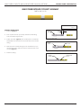
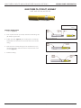
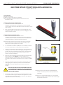
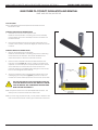
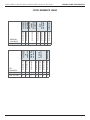
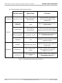
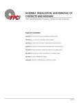
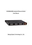
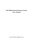
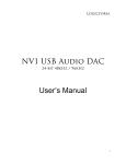
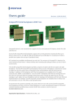
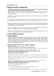
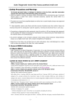
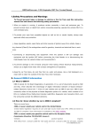
ASSEMBLY, INSTALLATION, AND REMOVAL OF
CONTACTS AND MODULES
FOR MINI POWER CONTACTS AND MODULES
TABLE OF CONTENTS
SECTION 1 RECEIVER CONTACT ASSEMBLY INSTRUCTIONS
SECTION 2 ITA CONTACT ASSEMBLY INSTRUCTIONS
SECTION 3 CONTACT INSTALLATION AND REMOVAL INSTRUCTIONS
SECTION 4 MODULE INSTALLATION AND REMOVAL INSTRUCTIONS
SECTION 5 CROSS REFERENCE TABLES
APPENDIX PRODUCT PERFORMANCE SPECIFICATIONS
1/25/10
VIRGINIA PANEL CORPORATION
MINI POWER CONTACTS AND MODULES USER’S MANUAL: SECTION 1
MINI POWER RECEIVER CONTACT ASSEMBLY
PART # 610 116 112
Dimensions shown: [millimeters]
inches
ASSEMBLY INSTRUCTIONS
SHRINK
TUBING
1. Strip wire (Figure A).
[7.62]
.30
2. Insert a piece of 0.125” [3.175 mm] diameter shrink tubing
1.00” [25.4 mm] long onto wire.
3. Solder and clean (Figure B). VPC solders per IPC’S J-STD-001.
NOTE: Make sure the heat from the solder does not shrink the
tubing.
4. Slide the piece of shrink tubing over the soldered end, up to
the inspection hole; make sure that the inspection hole is not
covered (Figure C).
Figure A. Strip length.
SHRINK
TUBING
SOLDER
Figure B. Solder, taking care not to shrink the tubing.
5. Shrink the tubing.
SHRINK
TUBING
INSPECTION
HOLE
Figure C. Ensure inspection hole is not covered.
1-1
For more information visit vpc.com
1/25/10
MINI POWER CONTACTS AND MODULES USER’S MANUAL: SECTION 2
VIRGINIA PANEL CORPORATION
MINI POWER ITA CONTACT ASSEMBLY
PART # 610 115 124 / 610 115 125
Dimensions shown: [millimeters]
inches
ASSEMBLY INSTRUCTIONS
1. Strip wire (Figure A).
2. Insert a piece of 0.125” [3.175 mm] diameter shrink tubing 1.00”
[25.4 mm] long onto wire.
3. Solder and clean (Figure B). VPC solders per IPC’S J-STD-001.
NOTE: Make sure the heat from the solder does not shrink the
tubing.
Figure A. Strip length.
4. Slide the piece of shrink tubing over the soldered end, up to
the inspection hole; make sure that the inspection hole is not
covered (Figure C).
5. Shrink the tubing.
Figure B. Solder, taking care not to shrink the tubing.
Figure C. Ensure inspection hole is not covered.
2-1
For more information visit vpc.com
1/25/10
MINI POWER CONTACTS AND MODULES USER’S MANUAL: SECTION 3
VIRGINIA PANEL CORPORATION
MINI POWER RECEIVER CONTACT INSTALLATION AND REMOVAL
PART # 610 116 112
TOOLS REQUIRED
Flat Blade Screwdriver
Phillips Head Screwdriver (for iCon modules)
Mini Coaxial/Mini Power Receiver/ITA Contact Extraction Tool,
Part # 910 112 104
CONTACT INSTALLATION INSTRUCTIONS
1.
Assemble the contact to the respective wire.
NOTE: For more information concerning the contact assembly
process please see contact assembly instructions in Section 1 of this
User’s Manual.
2. Insert the assembled contact into the back (wiring side) of the
assembled module. Once in place, pull the wire slightly to ensure
that the contact is seated.
CONTACT REMOVAL INSTRUCTIONS
1. Remove the module from the receiver frame.
NOTE: For more information concerning the process of removing
the module from the receiver frame, see module installation and
removal instructions in Section 4 of this User’s Manual.
NOTE: Some Mini Power receiver modules are one piece modules.
If your module does not have two flat head or Phillips screws
holding the module together, skip to step 4.
Figure A. Extraction tool, Part # 910 112 104.
2. Use a flat blade screwdriver (Phillips for iCon modules) to remove
the screws located at the top and bottom of the module.
3. Grasp the module halves and apply force in opposite directions,
rocking the ends of the module while slightly pulling the top of the
module away from the mating bottom section, until separated.
Be sure to open both sides of the module simultaneously or
contacts could be damaged.
4. Place the Mini Coax/Mini Power Receiver/ITA Contact Extraction
Tool, Part # 910 112 104 (Figure A), over the contact to be
removed/ replaced. Use care to keep the tool perpendicular to
the surface of the module, otherwise the tool or contact could be
bent.
5. Once the extraction tool is seated and the retaining tabs on the
retaining ring are compressed, push the tool into the module
(Figure B). The contact will be pushed out of the rear of the
module.
DO NOT PUSH THE TOOL INTO THE MODULE UNTIL THE
TIP OF THE EXTRACTION TOOL HAS FULLY SEATED INTO
THE MODULE AND COMPRESSED THE RETAINING RING
TABS ON THE CONTACT.
6. If necessary, replace the module cap using both hands to push
the separated halves together. Replace and tighten the module
retaining screws to a maximum torque of 1.5 in-lbs [0.17 Nm] (not
required for all Mini Power modules).
3-1
Figure B. Fully seat extraction tool before depressing.
NOTE: The process shown here uses standard/90 series
modules. The same process is used for modules from
other series.
NOTE: If you are using a hybrid module, you may need to
reference the User’s Manual for the other contact type
for extraction instructions.
For more information visit vpc.com
1/25/10
MINI POWER CONTACTS AND MODULES USER’S MANUAL: SECTION 3
VIRGINIA PANEL CORPORATION
MINI POWER ITA CONTACT INSTALLATION AND REMOVAL
PART # 610 115 124 / 610 115 125
TOOLS REQUIRED
Mini Coaxial/Mini Power Receiver/ITA Contact Extraction Tool,
Part # 910 112 104
CONTACT INSTALLATION INSTRUCTIONS
1.
Assemble the contact to the respective wire.
NOTE: For more information concerning the contact assembly
process please see contact assembly instructions in Section 2 of
this User’s Manual.
2.
Insert the assembled contact into the back (wiring side) of the
module. Once in place, pull the wire slightly to ensure the contact
is seated.
CONTACT REMOVAL INSTRUCTIONS
1.
Remove the module from the ITA frame.
NOTE: For more information concerning the process of removing
the module from the ITA frame, see module installation and
removal instructions in Section 4 of this User’s Manual.
2.
Place the Mini Coax/Mini Power Receiver/ITA Extraction Tool,
Part # 910 112 104 (Figure A), over the contact to be removed/
replaced. Use care to keep the tool perpendicular to the surface
of the module as not to bend the tool or the contact to be
removed. Rotate the tool slightly while pushing it into the counter
bore on the mating side of the module.
3.
Once the extraction tool is seated properly and the tabs on the
retaining ring are compressed (Figure B), push the tool into the
module. The contact will be pushed out of the rear of the module.
Figure A. Extraction tool, Part # 910 112 104.
DO NOT PUSH THE TOOL INTO THE MODULE UNTIL THE
TIP OF THE EXTRACTION TOOL HAS BEEN FULLY SEATED
INTO THE MODULE AND COMPRESSED THE RETAINING
RING TABS ON THE CONTACT.
NOTE: The process shown here uses standard/90 series modules. The
same process is used for modules from other series.
Figure B. Fully seat extraction tool befoere depressing.
NOTE: If you are using a hybrid module, you may need to reference the
User’s Manual for the other contact type for extraction instructions.
3-2
For more information visit vpc.com
1/25/10
MINI POWER CONTACTS AND MODULES USER’S MANUAL: SECTION 4
VIRGINIA PANEL CORPORATION
MINI POWER STANDARD/90 SERIES MODULE INSTALLATION AND REMOVAL
TOOLS REQUIRED
3
/32 Allen Wrench
INSTALLATION INSTRUCTIONS
1.
Place the module in the receiver or ITA until the upper and
lower module screws touch the mating holes in the inner
frame. Ensure that Position 1 is located at the top for systems
in which the modules are oriented vertically or to the left for
systems in which the modules are oriented horizontally.
2.
Using a 3/32 Allen wrench, tighten the top screw 1 to 2 full
revolutions, while pushing lightly against the face of the
module.
3.
Maintain this pressure while tightening the bottom screw 1 to
2 full revolutions.
4.
Repeat this sequence until the module is seated. Torque the
screw to 4 in-lbs [0.45 Nm].
POSITION 1
REMOVAL INSTRUCTIONS
1.
To remove, loosen the top screw 1 to 2 full revolutions. Loosen
bottom screw 1 to 2 full revolutions.
2.
Repeat this sequence until the module is separated from the
receiver or ITA.
Figure A. Receiver Module.
NOTE: For optimum performance and system longevity, distribute
the contact load evenly throughout the module.
Figure B. ITA Module.
4-1
For more information visit vpc.com
1/25/10
MINI POWER CONTACTS AND MODULES USER’S MANUAL: SECTION 4
VIRGINIA PANEL CORPORATION
MINI POWER ICON MODULE INSTALLATION AND REMOVAL
TOOLS REQUIRED
Phillips Head Screwdriver
INSTALLATION INSTRUCTIONS
Note: The receiver strain relief plate or the ITA cover may need to be
removed prior to installing or removing an iCon module. Please
refer to the appropriate User’s Manual for instructions on how to
perform these steps.
1. Place the module in the receiver or ITA until the upper and lower
module screws touch the mating holes in the inner frame. Install
modules such that Position 1 is located at the top of the ITA/
receiver frame.
2. Using a Phillips head screwdriver, tighten the top screw 1 to 2 full
revolutions, while pushing lightly against the face of the module.
3. Maintain this pressure while tightening the bottom screw 1 to 2
full revolutions.
4. Repeat this sequence until the module is seated. Torque the
screw to 1.5 in-lbs [0.16 Nm].
REMOVAL INSTRUCTIONS
1. To remove, loosen the top screw 1 to 2 full revolutions. Loosen
bottom screw 1 to 2 full revolutions.
Figure A. Receiver Module.
2. Repeat this sequence until the module is separated from the
receiver or ITA.
NOTE: For optimum performance and system longevity, distribute
the contact load evenly throughout the module.
Figure B. ITA Module.
4-2
For more information visit vpc.com
1/25/10
5-1
510 114 107
510 161 102
510 161 103
510 161 104
910 112 104
ITA
CONTACTS
610 115 124
610 115 125
EXTRACTION
ICON ITA
MODULES
510 104 123
510 104 206
510 113 120
510 160 102
510 160 103
510 160 104
910 112 104
610 116 112
510 108 178
STANDARD/
90 SERIES
ITA
MODULES
CASS/ 80
SERIES ITA
MODULE
RECEIVER
CONTACTS
510 108 115
EXTRACTION
ICON
RECEIVER
MODULES
STANDARD/
90 SERIES
RECEIVER
MODULES
CASS/ 80
SERIES
RECEIVER
MODULE
MINI POWER CONTACTS AND MODULES USER’S MANUAL: SECTION 5
X
X
X
X
X
X
X
X
X
X
X
X
X*
X
X
X
X
X
X
X
X
For more information visit vpc.com
VIRGINIA PANEL CORPORATION
CROSS REFERENCE TABLES
*Navy Part Number does not exist for Part # 610 115 125
1/25/10
MINI POWER CONTACTS AND MODULES USER’S MANUAL: APPENDIX
VIRGINIA PANEL CORPORATION
Product Performance Specification
Mini Power Connector
1. Scope
1.1 Content
This specification covers the performance, tests and quality requirements for the Mini Power
Connector and connector system. This contact is a separable electrical connection device.
Variations of this contact can be crimped to 8, 12, and 14 AWG wire or soldered to wires up to 8
AWG in size. All Mini Power contact types are to be used in connector modules.
1.2 Qualification Testing
When tests are performed on subject product line, the following procedures shall be used:
All inspections shall be performed using applicable inspection plans and product drawings. Upon
completion of qualification testing, this specification will be assigned a number and be classified,
as a Product Qualification Report which will be identified in section 2.
2. Applicable Documents
2.1 Content
The following documents form a part of this specification to the extent specified herein. Unless
otherwise specified, the latest edition of the document applies. In the event of a conflict between
requirements of this specification and product drawing, product drawing will take precedence. In
the event of a conflict between requirements of this specification and referenced documents, this
specification shall take precedence.
2.2 Documents
A. Standards
• EIA-364-13
• MIL-STD-1344
• MIL-STD-202
B. Qualification Test Plans
• MET ESL Test Plan #24785
C. Product Qualification Reports
• MET Test Report #31238T
D. Product Drawings
Housing
• 510104123
• 510104246
• 510108115
• 510108132
1 of 5
For more information visit vpc.com
Rev. 5 – 9/22/09
MINI POWER CONTACTS AND MODULES USER’S MANUAL: APPENDIX
VIRGINIA PANEL CORPORATION
Contacts
• 610116112
• 610116124
• 610116125
• 610115124
• 610115125
• 610115127
• 610115128
• 610115129
• 610115130
3. Requirements
3.1 Design and Construction
Product shall be of design, construction and physical dimensions specified on applicable product
drawings.
3.2 Materials
A. Female Contact
• Brass
• Gold over nickel plating per MIL-DTL-45204D
B. Male contact
• Beryllium Copper
• Gold over nickel plating
C. Housing
• G10 Epoxy Glass or Black PPS
3.3 Ratings
A. Voltage
• AC up to 100 MHz
• DC
B. Current
• 16 AWG: 25 ampere maximum
• 14 AWG: 30 ampere maximum
• 12 AWG: 40 ampere maximum
• 8 AWG: 50 ampere maximum
C. Temperature
• -50oC to +105oC
3.4 Performance and Test Description
Product is designed to meet electrical, mechanical, and environmental requirements specified in
Figure 1. Unless otherwise specified, all tests should be performed at ambient environmental
conditions.
2 of 5
For more information visit vpc.com
Rev. 5 – 9/22/09
VIRGINIA PANEL CORPORATION
MINI POWER CONTACTS AND MODULES USER’S MANUAL: APPENDIX
3.5 Test Requirements and Procedures Summary
Preliminary
Test Description
Requirement
Procedure
Examination of Product
Meets requirements of
product drawing
Visual, dimensional, and functional
examination per applicable quality
inspection plan
Initial Contact
Resistance
< 8mΩ
Measure with digital Ohmmeter using 4
terminal method
Current Rating
30° C maximum
temperature rise
100% of pin positions populated and
subjected to 50A current with 8 AWG wire
Dielectric Breakdown
Current leak < 20 mA
1500 VDC between pins in a module for
no less then 60 seconds
Capacitance
< 3 pF
Capacitance measured between adjacent
contacts in a module
Durability
See test sequence: Figure 2
EIA-364-9: Mate and unmate sample for
20000 cycles
Mating Force
Max 5.7 lbs force per
contact
EIA-364-13: Measure force necessary to
mate samples at a normal rate of
engagement of the ITA
Unmating Force
Max 5.0 lbs force per
contact
EIA-364-13: Measure force necessary to
unmate samples at a normal rate of
disengagement of the ITA
Electrical
Mechanical
Figure 1. Test Requirements and Procedure Summary
3 of 5
For more information visit vpc.com
Rev. 5 – 9/22/09
VIRGINIA PANEL CORPORATION
MINI POWER CONTACTS AND MODULES USER’S MANUAL: APPENDIX
3.6 Product Qualification and Requalification Test Sequence
Test or Examination
Examination of Product
Contact Resistance
Current Rating
Dielectric Breakdown
Capacitance
Frequency Range
Durability
Mating Force
Unmating Force
I
Test Group
II
III
1, 9
2, 8
1, 7
2
3
4
5
6
5
3, 7
4, 6
1, 4
2
3
Figure 2. Test Sequence
Numbers indicate the sequence in which the tests are performed. For test group sample
selection see 4.1 A.
4. Quality Assurance Provisions
4.1 Qualification Testing
A. Sample Selection
Samples shall be prepared in accordance with applicable instruction sheets and shall be
selected at random from current production. All test groups shall each consist of a
minimum of 5 connectors containing at least 30 contacts total each and equal posts to
mate with receptacles. Test group 1 shall have both minimum and maximum position
size connectors.
B. Test Sequence
Qualification inspection shall be verified by testing samples as specified in Figure 2.
4.2 Re-Qualification Testing
If changes significantly affecting form, fit or function are made to product or manufacturing
process, product assurance shall coordinate re-qualification testing, consisting of all or part of
original testing sequence as determined by development/product, quality and reliability
engineering
4.3 Acceptance
Acceptance is based on verification that product meets requirements of Figure 1. Failures
attributed to equipment, test set-up or operator deficiencies shall not disqualify product. When
product failure occurs, corrective action shall be taken and samples resubmitted for qualification.
Testing to confirm corrective action is required before re-submittal.
4 of 5
For more information visit vpc.com
Rev. 5 – 9/22/09
MINI POWER CONTACTS AND MODULES USER’S MANUAL: APPENDIX
VIRGINIA PANEL CORPORATION
4.4 Quality Conformance Inspection
A Certificate of Conformance (C of C) dimensional inspection must be completed for all samples
prior to Qualification testing. The applicable quality inspection plan will specify sampling
acceptable quality level to be used. Dimensional and functional requirements shall be in
accordance with applicable product drawing and this specification.
5 of 5
Rev
Date
Rev Change
Prepared By
1
2
3
4
5
3/25/08
10/21/08
6/16/09
8/03/09
9/22/09
Original Release
Updated
Updated
Add Crimp Contact P/Ns
Updated
Eric Husted
Eric Husted
Eric Husted
Eric Husted
Eric Husted
For more information visit vpc.com
Rev. 5 – 9/22/09